Page is loading ...

W475N, W485N -00520/121663
-00521/400019-402182
W4105N -00595/106656
-00521/400164-402182
W4130N -00595/106657
-00521/400104-402182
W4180N -00650/107383
W4250N -00725/105493
W4330N -00795/102509
W475M, W485M -00520/120946
-00521/400282-402182
W4105M -00595/106646
-00521/401173-402182
W4130M -00595/106611
-00521/400106-402182
W4180M -00650/107383
W4250M -00725/105493
W4330M -00795/102509
Service Manual
W465H–W4300H, W475M–W4330M,
W475N–W4330N
Compass Control
Up to machine number:
438 9227-31/EN
09.20


3
Contents
Contents
Safety precautions ....................................................................................... 5
Technical data .............................................................................................. 7
Machine presentation ............................................................................... 13
Description ............................................................................................ 13
Function ................................................................................................. 14
Program unit .......................................................................................... 16
Motor and motor control ....................................................................... 17
Door lock ............................................................................................... 18
Heating .................................................................................................. 19
Water connections ................................................................................19
Rear electric module .............................................................................19
Detergent compartment ........................................................................ 20
Drain valve ............................................................................................. 20
Frame and suspension .......................................................................... 20
Trouble shooting ........................................................................................ 21
General information on troubleshooting ................................................ 21
Fault code .............................................................................................. 22
Engaging servicemode .......................................................................... 24
Description of fault codes and causes .................................................. 25
Program unit .............................................................................................. 45
Description ............................................................................................ 45
Menu tree .............................................................................................. 47
Engaging servicemode .......................................................................... 48
Service program .................................................................................... 49
Config 1 ................................................................................................. 56
Activate wash progr............................................................................... 68
Unbalance detection ............................................................................. 69
I/O modules ................................................................................................ 71
General .................................................................................................. 71
Function options via the service program ............................................. 72
Function options via program designation ............................................ 73
Function options for Type 1 and Type 2 I/O modules ........................... 74
Replacing of I/O module ........................................................................ 75
External connections to I/O module type 2 ........................................... 76
Machines with I/O module type 3 .......................................................... 86
Addressing I/O modules ........................................................................ 87
Door and door lock .................................................................................... 89
Description ............................................................................................ 89
Function ................................................................................................. 90
Repairs .................................................................................................. 92
Motor and motor control ............................................................................ 95
Warnings................................................................................................ 95
Description ............................................................................................ 96
Function ................................................................................................. 98
LED indications.................................................................................... 101
Repairs ................................................................................................ 102
Adjustments......................................................................................... 103

4
Contents
Drain valve ................................................................................................ 105
Description .......................................................................................... 105
Function ............................................................................................... 106
Repairs ................................................................................................ 107
Detergent compartment ........................................................................... 109
Description .......................................................................................... 109
Heating ..................................................................................................... 111
Description .......................................................................................... 111
Function ............................................................................................... 112
Repairs ................................................................................................ 114
Payment systems ..................................................................................... 115
Abbreviations ........................................................................................... 117
Preventive maintenance ........................................................................... 119
The manufacturer reserves the right to make changes to design and
com ponent specifications.

5
Safety Precautions
All external equipment which is connected to the machine must be CE/EMC-approved
and connected using an approved shielded cable.
Safety Precautions
The machine is only intended for water-wash use.
Do not allow minors to use the machine.
Do not hose down the machine with water.
The machine's door lock must under no circumstances be bypassed.
If the machine develops a fault, this must be reported to the person in charge as soon
as possible. This is important both for your safety and that of others.
The machine is not intended to be used by people (including minors) with reduced
physical or mental capacity or lack of experience and knowledge. Such people must
be instructed in the use of the machine by a person who has responsibility for their
safety. Minors must be supervised to ensure that they do not play with the machine.
Warnings
The service manual contains the following warnings concerning serious personal injury.
Next to each warning is a reference to the page and section where the warning text is located
in the manual.
DANGER
Take care when measuring the motor control system since all components have a
potential difference of approximately 300V in relation to protective earth and neutral.
The components will contain dangerous voltages when the green LED on the motor
control board is on.
The motor control system will remain live for 10-30 seconds after cutting the power to
the machine and the motor has stopped running.

6

7
Technical data
W465H W475H W4105H W4130H W4180H W4240H W4300H
65 75 105 130 180 240 300
520 520 595 650 725 795 795
49 49 49 49 44 42 42
1100 1100 1025 980 930 890 820
5.4/7.5 5.4/7.5 7.5/10 13 18 23 23
x x x x x x x
x x x x x x x
350 350 350 350 350 350 300
144 159 201 267 350 400 509
W465H W475H W4105H W4130H W4180H W4240H W4300H
DN20 DN20 DN20 DN20 DN20 DN20 DN20
3/4" 3/4" 3/4" 3/4" 3/4" 3/4" 3/4"
200-600 200-600 200-600 200-600 200-600 200-600 200-600
50-1000 50-1000 50-1000 50-1000 50-1000 50-1000 50-1000
20 20 20 20 60 60 60
50/75 50/75 50/75 75 75 75 75
170 170 170 170 170 170 170
DN15 DN15 DN15 DN15 DN15 DN15 DN15
1/2" 1/2" 1/2" 1/2" 1/2" 1/2" 1/2"
300-600 300-600 300-600 300-600 300-600 300-600 300-600
50-800 50-800 50-800 50-800 50-800 50-800 50-800
Innerdrum
volume litres
diameter mm
Drum speed
wash
extraction
rpm
Heating
electricity kW
steam
hot water
G-factor
Weight, net kg
Connections
Water valves
connection
BSP
Rec. water pressure
kPa
Functioning limits
for water valve
kPa
Capacity
at 300 kPa
l/min
Drain valve
outer Ø mm
Draining capacity
l/min
Steam valve
connection
BSP
Rec. steam pressure
kPa
Functioning limits for
steam valve
kPa
Technical data

8
Technical data
W475N/M W485N/M W4105N/M W4130N/M W4180N/M W4250N/M W4330N/M
75 85 105 130 180 250 330
520 520 595 595 650 725 795
49 49 49 49 44 44 42
528/694 528/694 494/649 494/649 471/619 446/587 427/561
2.0/3.0/ 2.0/3.0/5.6 3.0/6.5/ 3.0/ 4.8/9.3
5.4/5.6/7.5 5.4/7.5 7.5/10 7.5/10 13 18 23
x x x x x x x
x x x x x x x
81/140 81/140 81/140 81/140 81/140 81/140 81/140
130 136 170 175 228 287 330
W475N/M W485N/M W4105N/M W4130N/M W4180N/M W4250N/M W4330N/M
DN20 DN20 DN20 DN20 DN20 DN20 DN20
3/4" 3/4" 3/4" 3/4" 3/4" 3/4" 3/4"
200-600 200-600 200-600 200-600 200-600 200-600 200-600
50-1000 50-1000 50-1000 50-1000 50-1000 50-1000 50-1000
20 20 20 20 60 60 60
75 75 75 75 75 75 75
170 170 170 170 170 170 170
DN15 DN15 DN15 DN15 DN15 DN15 DN15
1/2" 1/2" 1/2" 1/2" 1/2" 1/2" 1/2"
300-600 300-600 300-600 300-600 300-600 300-600 300-600
50-800 50-800 50-800 50-800 50-800 50-800 50-800
Innerdrum
volume litres
diameter mm
Drum speed
wash
extraction
rpm
Heating
electricity kW
steam
hot water
G-factor
Weight, net kg
Connections
Technical data
Water valves
connection
BSP
Rec. water pressure
kPa
Functioning limits
for water valve
kPa
Capacity
at 300 kPa
l/min
Drain valve
outer Ø mm
Draining capacity
l/min
Steam valve
connection
BSP
Rec. steam pressure
kPa
Functioning limits for
steam valve
kPa

9
Technical data
K
N
M
R
P
6
F
5
1
O
G
I
L
3
2
7
4
5283 B
A B C D E F G H I K L M N O P R S
W465H 720 690 1115 355 720 825 45 1030 220 1010 135 910 830 360 100 240 –
W475H 720 690 1115 355 720 825 45 1030 220 1010 135 910 830 360 100 240 –
W4105H 830 705 1300 365 740 910 45 1115 220 1095 135 995 910 415 100 295 –
W4130H 910 785 1325 435 825 1035 125 1245 215 1225 300 1125 – – 100 305 455
W4180H 970 870 1410 470 910 1120 115 1330 230 1290 315 1205 370 410 100 335 485
W4240H 1020 915 1445 500 955 1155 100 1360 215 1320 300 1240 350 360 100 360 510
W4300H 1020 1060 1445 500 1135 1155 100 1360 215 1320 300 380 – – 100 360 330
A
8
9
10
C
D
5281 B
B
E
6
5282 B
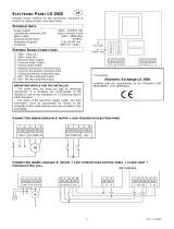
W465H, W475H, W4105H, W4130H
A
9
10
8
D
C
5377 A
5379 A
B
E
6
G
S
L
M
I
5
1
F
6
P
R
K
H
5378 A
7
3
2
2
W4180H, W4240H, W4300H
Rear side
1 Electrical connection
2 Cold water
3 Hot water
4 Hard water
5 Steam connection
6 Drain
7 Liquid detergent supply
8 Control panel
9 Soap box
10 Door opening, W465H, W475H: ø 310, W4105H: ø 365, W4130H: ø 395, W4180H, W4240H, W4300H: ø 435
Front
Right side
Rear side
Front
Right side

10
Technical data
A B C D E F G H I K L M N O P R
W475N/M 660 690 1115 355 725 825 45 1030 215 1010 130 830 385 - 100 210
W485N/M 660 730 1115 355 765 825 45 1030 215 1010 130 830 385 - 100 210
W4105N/M 720 705 1200 365 740 910 45 1115 215 1095 130 910 420 - 100 235
W4130N/M 720 790 1200 365 825 910 45 1115 215 1095 130 910 420 - 100 235
W4180N/M 750 880 1325 435 915 1035 45 1245 130 1225 210 1040 325 295 100 225
W4250N/M 830 955 1410 470 990 1120 45 1330 160 1290 245 1125 325 325 100 265
W4330N 910 1040 1445 500 1075 1155 45 1365 160 1325 245 1155 280 325 100 210
8
7
C
D
A
10
5281
B
E
5
5282
N
G
I
F
L
R
P
H
M
K
5
4
1
3
2
6
5283
9
W475N/M-W4130N/M
M
P
F
K
I
L
G
R
H
O
N
4
1
5
3
2
9
6
5459
W4180N/M-W4330N
Rear side
1 Electrical connection
2 Cold water
3 Hot water
4 Steam connection
5 Drain
6 Liquid detergent supply
7 Control panel
8 Soap box
9 Water reuse
10 Door opening, W475N/M, W485N/M: ø310, W4105N, W4130M: ø365, W4130N, W4180M: ø395, W4180N,
W4250N/M, W4330N/M: ø435
Front
Right side
Rear side

11
Technical data
W465H W475H W4105H W4130H W4180H W4240H W4300H
18.3 18.3 17.1 16.3 15.5 14.8 13.7
1.8 ± 0.5 1.9 ± 0.5 2.5 ± 0.5 3.1 ± 0.5 4.2 ± 1.0 5.2 ± 1.0 6.2 ± 1.2
Frequency of the
dynamic force
Hz
Max floor load
at extraction
kN
W475N/M W485N/M W4105N/M W4130N/M W4180N/M W4250N/M W4330N/M
Frequency of the
dynamic force
Hz 9.3 9.3/11.6 8.7/10.8 8.7/10.8 8.3/10.3 7.9/9.8 7.5/9.4
Max floor load
at extraction 1.6 ± 2.8/ 1.7 ± 3.1/ 2.1 ± 3.6/ 2.3 ± 4.1/ 2.9 ± 4.7/ 3.7 ± 5.3/ 4.5 ± 5.8/
kN 1.2 ± 2.6 1.7 ± 3.3 2.1 ± 4.0 2.3 ± 4.7 2.7 ± 5.9 3.7 ± 7.4 4.2 ± 8.8


13
Machine presentation
1
Machine presentation
Description
General
The machines covered in this service manual
include the following models:
Drum volume Model name
(litres)
65 W465H
75 W475H/M/N
85 W485M/N
105 W4105H/M/N
130 W4130H/M/N
180 W4180H/M/N
240 W4240H
250 W4250M/N
300 W4300H
330 W4330M/N
The machines feature an electronic programme
unit with fixed washing programmes that may be
changed using optional accessories. The pro-
gramme unit also has an in-built self-diagnosis
programme, which increases the possibilities for
quick troubleshooting.
The motor is frequency-controlled and is control-
led by an advanced motor control. This allows
precise and flexible control of the motor rpm for
any application.
The machines are supplied to customer specifi-
cations with e.g. electric or steam heating or no
heating, and may be connected to various com-
binations of cold, warm and hard water.
6569
1

14
Machine presentation
2
Function
General
This section presents a general overview of the functions of the machine.
Most functions are then presented in detailed in separate chapters later on
in this service manual.
The machine is freely suspended, which means the outer drum and motor
are mounted on a supporting ”cradle” that rests on four shock absorbers
for dampening the imbalance in the machine.
The washer drum (inner drum) is belt driven by a motor. This motor is loca-
ted at the bottom of the machine and is mounted on the cradle with a belt
tensioner. The inner drum is mounted to the outer drum at the rear plate
with two bearings sealed against leakage with sealing rings.
The drain valve is a water-controlled diaphragm valve alternatively, an
electrical drain valve or drain pump.
The door is of sturdy type that is interlocked with a lock module when in
operation.
The control panel contains a program knob for selecting the fixed wash
programs and a display.
The program unit is mounted inside the control panel. Contactor, water
valves, etc., are located at the back of the machine.

15
Machine presentation
6562
11
18
17
13
14
12
16
15
2
1
5
4
3
2
8
7
6
9
10
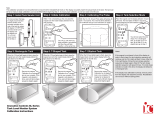
1. Detergent drawer
2. Water inlet valves
3, Power supply
4. I/O-board
5. Rear electrical module
6. Motor control
7. Outer drum
8. Coil spring (not M- and N-model)
9. Motor
10. Shock absorber (not M- and N-model)
11. Avloppsventil
12. Support
13. Door
14. Door lock
15. Program knob
16. Display
17. Control panel
18. Program unit
H - model shown

16
6211
5190
3
4
3
K21
1
2
4
5
6
Program unit
The control panel contains a program knob and
a display. The panel can also be equipped with
two preset buttons.
The control panel and display are used by:
• theusertoselectthemachine’sxedwash
programs, to select up to two options for
each wash program and for information on
the wash process and any fault indicators.
• servicepersonnelfornavigationandcontrol
oftheprogramunit’sserviceprogram.
• programmingpersonnelforsettingandpro-
gramadjustmentintheprogramunit’ssoft-
ware.
If present, the preset buttons are used for direct
start of two preset wash programs.
Using information on torque values from the
motor, the weight of each wash is measured
before each wash program in order to adapt the
amount of water used for washing.
The program unit controls the water valves, drain
valve and heating via an I/O board in the rear
electrical module. Control signals to external
units, such as detergent pumps or external water
valves can also be engaged here.
3
4
Program unit
1. Program unit A1
2. I/O-board A11,
Outputs for water, detergent and drain.
3. Heater element
4 Water valves
5. Drain valve
6. Power supply
Machine presentation

17
6211
5189
5
6
2
1
3
2
M1
1
1. Motor control
2. Motor
1. Program unit A1
2. Power supply
3. Motor control U1
Motor and motor control
The washer drum (inner drum) is belt driven by a
frequency controlled motor. The motor is located
on a motor shelf under the outer drum and has
been arranged with a belt tensioner.
Motor control is microprocessor controlled and
can control the acceleration of the drum, its rpm
and its retardation very precisely.
Motor control communicates with the program
unit through a serial interface.
Themachine’smotorandmotorcontrolarede-
scribed in more detail in the section Motor.
5
6
H - model shown
Machine presentation

18
7
8
6568
2
6658
M1
6
1
5
7
1
4
3
2
Door lock
The door lock is electromechanical with twin sa-
fety breakers. The lock is bi-stable, i.e. the lock
must be given an active signal from the program
unit to lock as well as unlock the door.
A separate circuit integrated in the program unit
checks and controls the locking and unlocking
of the door through a lock module. The circuit
has separate controls that the drum is empty
and that it is stationary. Through sensors in the
lockmodule,thecircuitchecksthedoor’sclo-
sed and locked position. Together with other
controls the program unit conducts, this will
guarantee the door cannot be opened by mis-
take.
Themachine’sdooranddoorlockaredescri-
bed in more detail in the section Door and door
lock.
7
8
1. Program unit
2. Lock module
1. Program unit A1
2. Temperature sensor B1
3. Level switch B2
4. Level switch B4
5. Motor control U1
6. Lock module A111
7. Rotation sensor B3
Machine presentation

19
6562
1
2
6281
2 (alt.)
34
6271
2 (alt.)
Heating
Electric heating heats the washing water with
three elements accessible from the front of the
machine.
Themachine’sheatingsystemisdescribedmore
thoroughly in the section Heating.
Water connections
The machine can have one, two, three or four wa-
ter inlet valves depending on the machine size and
customer requirements.
In this unit there are also eight connections for an
external detergent feeder.
Rear electric module
Contains the main switch or terminal block for
incoming power, heating contactor, I/O board with
outputsforcontrollingthemachine’swaterand
drain valves and heating. Some machines have an
additional I/O board with terminal blocks for con-
necting e.g. external detergent feeder.
9
9
10
1. Water connections
2. Heating element
1. Rear electric module
2. Power supply connection
3. Distribution board, I/O board 2
4. Contactor K21 (Heat)
9
10
Machine presentation

20
11
5
4
6
2
3
1
6582
Detergent compartment
The detergent compartment has four compart-
ments for prewash, main wash, rinse and
bleaching agent/liquid detergent.
Themachine’sdetergentcompartmentisdescri-
bed more thoroughly in the section Detergent
compartment.
Drain valve
The valve is a diaphragm valve that is opened
and closed through water pressure. The control
valve is mounted by the water valves.
Themachine’sdrainvalveisdescribedmore
thoroughly in the section Drain valve.
Frame and suspension
The machines are freely suspended, i.e. the
drum package can move and is suspended in
relation to the frame. In this way, a minimum of
vibration passes to the bottom plate, which in
turn simplifies installation as a concrete founda-
tion is not required.
The machine has four shock absorbers between
the bottom plate and the drum package.
Themachine’sframeisdescribedmore
thoroughly in the section Frame.
11
11
11
1. Detergent compartment
2. Outer Support
3. Shock absorbers
4. Drain valve
5. Inner support
6. Coil spring
Machine presentation
/