Page is loading ...

DOC-3200-2
User's Manual

DOC-3200-2, Current Version
Title: HERMES DXD – User’s Manual
ID-no.: DOC-3200-2
Date: 2003-09
main issue update
chapter 1 new
chapter 2 new
chapter 3 new
chapter 4 new
chapter 5 new
chapter 6 new
chapter 7 new
new: The corresponding chapters are new or completely revised.
corr.: Passages of the corresponding chapter were corrected; see modification bars.
add.: Passages of the corresponding chapter were added; see modification bars.
Document History
Modifications which result in a new version are indicated by a vertical bar.
Keep this sheet!

Trademarks
Brand and product names mentioned in this manual may be trademarks, registered trademarks or
copyrights of their respective holders. All brand and product names mentioned in this manual
serve as comments or examples and are not to be understood as advertising for the products or
their manufacturers.
Copyright © 1999 - 2003 by Barco Control Rooms GmbH
Die Weitergabe sowie die Vervielfältigung aller Unterlagen, die von uns überlassen werden, deren
Verwertung und Mitteilung ihres Inhaltes an Dritte ist nicht gestattet, soweit dies nicht ausdrück-
lich zugestanden ist. Urheberrechte, insbesondere auch solche an Software, werden nur insoweit
übertragen, als es für die Erreichung des speziellen Vertragszwecks erforderlich ist. Zuwider-
handlungen können zu Schadensersatz verpflichten. Alle Rechte aus der Erteilung eines Patents
oder der Eintragung eines Gebrauchsmusters verbleiben bei uns.
Copyright © 1999 - 2003 by Barco Control Rooms GmbH
All rights reserved. No part of this document may be copied, reproduced or translated. It shall not
otherwise be recorded, transmitted or stored in a retrieval system without the prior written consent
of Barco Control Rooms GmbH.
Guarantee and Compensation
Barco Control Rooms GmbH provides a guarantee relating to perfect manufacturing as part of the
legally stipulated terms of guarantee. On receipt, the purchaser must immediately inspect all deliv-
ered goods for damage incurred during transport, as well as for material and manufacturing faults.
Barco Control Rooms GmbH must be informed immediately in writing of any complaints.
The period of guarantee begins on the date of transfer of risks, in the case of special systems and
software on the date of commissioning, at the latest 30 days after the transfer of risks. In the event
of justified notice of complaint, Barco Control Rooms GmbH can repair the fault or provide a re-
placement at its own discretion within an appropriate period. If this measure proves to be impossi-
ble or unsuccessful, the purchaser can demand a reduction in the purchase price or cancellation of
the contract. All other claims, in particular those relating to compensation for direct or indirect
damage, and also damage attributed to the operation of software as well as to other services pro-
vided by Barco Control Rooms GmbH, being a component of the system or independent services,
will be deemed invalid provided the damage is not proven to be attributed to the absence of prop-
erties guaranteed in writing or due to the intent or gross negligence on the part of Barco Control
Rooms GmbH
If the purchaser or a third party carries out modifications or repairs on good delivered by Barco
Control Rooms GmbH, or if the goods are handled incorrectly, in particular if the systems are
commissioned or operated incorrectly or if, after the transfer of risks, the goods are subject to in-
fluences not agreed upon in the contract, all guarantee claims of the purchaser will be rendered in-
valid. Not included in the guarantee coverage are system failures which are attributed to programs
or special electronic circuitry provided by the purchaser, e. g. interfaces. Normal wear as well as
normal maintenance are not subject to the guarantee provided by Barco Control Rooms GmbH ei-
ther.
The environmental conditions as well as the servicing and maintenance regulations specified in
this manual must be complied with by the customer.

Revision sheet
To:
Barco Control Rooms GmbH
An der Rossweid 5, D-76229 Karlsruhe
Phone: +49-721-6201-0, Fax: +49-721-6201-298
E-mail:
BarcoProjection
Noordlaan5, B-8520 Kuurne, Belgium
Phone: (32) (56) 36-8211, Fax: (32) (56) 36-8251
E-mail: [email protected] , Web:
www.barcocontrolrooms.com
From:
Date:
Please correct the following points in the documentation mentioned above:
page wrong correct

Table of Contents
1 Preliminary Remarks.................................................................................................................... 1-1
1.1 How this manual is organized ............................................................................................. 1-2
1.2 Styles and Symbols ............................................................................................................. 1-3
1.3 Safety Information............................................................................................................... 1-4
1.3.1 Precautions.................................................................................................................. 1-6
1.3.2 Unpacking of Devices ................................................................................................1-6
1.3.3 Transport of Devices .................................................................................................. 1-6
1.3.4 Modification of Devices ............................................................................................. 1-6
2 Summary ...................................................................................................................................... 2-1
2.1 Connecting the graphical controller and the projection cubes............................................ 2-2
2.2 Assigning inputs to outputs .................................................................................................2-3
2.3 Remote Control ...................................................................................................................2-3
3 Getting started .............................................................................................................................. 3-1
3.1 Examining ...........................................................................................................................3-2
3.1.1 The Front Panel .......................................................................................................... 3-2
3.1.2 The Back Panel........................................................................................................... 3-4
3.2 Native device settings (default settings).............................................................................. 3-5
3.3 DDC Capability................................................................................................................... 3-5
3.4 Cabling ................................................................................................................................3-6
3.4.1 Power Supply..............................................................................................................3-6
3.4.2 Digital Input and Output.............................................................................................3-7
3.4.3 Remote Control........................................................................................................... 3-7
3.5 Operating Hermes DXD...................................................................................................... 3-8
4 Remote Control ............................................................................................................................ 4-1
4.1 Cabling ................................................................................................................................4-2
4.1.1 Cabling of Hermes DXD (number of devices < 20) .................................................. 4-2
4.1.2 Cabling of Hermes DXD (number of devices > 20) .................................................. 4-3
4.2 Definition of Protocol.......................................................................................................... 4-3
4.2.1 Connection Settings.................................................................................................... 4-3
4.2.2 Communication .......................................................................................................... 4-3
4.2.3 Structure of Messages................................................................................................. 4-4
4.2.4 Acknowledge .............................................................................................................. 4-4
4.2.5 Types of RCS Classes................................................................................................. 4-5
4.3 How to calculate the checksum........................................................................................... 4-5
4.4 The Status Register.............................................................................................................. 4-6

5 Controlling Hermes DXD ............................................................................................................ 5-1
5.1 Valid Commands for Hermes DXD .................................................................................... 5-2
5.2 Request commands.............................................................................................................. 5-3
5.3 Switching commands ..........................................................................................................5-4
5.3.1 Switching the Digital Output 1................................................................................... 5-4
5.3.2 Switching the Digital Output 2................................................................................... 5-6
5.4 Enabling/Disabling auto switch ..........................................................................................5-9
5.5 Commands referring to settings ........................................................................................5-11
5.6 Reading the status register.................................................................................................5-14
5.7 Reading the product identification .................................................................................... 5-15
5.8 Error messages ..................................................................................................................5-16
6 Broadcast addressing mode.......................................................................................................... 6-1
6.1 Structure of message ........................................................................................................... 6-2
6.2 Processing a command in broadcast mode.......................................................................... 6-2
6.3 Commands for broadcast addressing................................................................................... 6-3
7 Technical Data ............................................................................................................................. 7-1
7.1 General Data........................................................................................................................7-2
7.1.1 Dimensions ................................................................................................................. 7-2
7.1.2 Power Supply..............................................................................................................7-2
7.1.3 Operating Conditions.................................................................................................. 7-3
7.2 Interfaces ............................................................................................................................. 7-4
7.2.1 Remote In.................................................................................................................... 7-4
7.2.2 Remote Out................................................................................................................. 7-4
7.2.3 Digital In..................................................................................................................... 7-5
7.2.4 Digital Out .................................................................................................................. 7-5
7.3 Parts List..............................................................................................................................7-6
7.3.1 Hermes DXD .............................................................................................................. 7-6
7.3.2 Remote Control........................................................................................................... 7-6
7.3.3 User’s Manuals ........................................................................................................... 7-6
7.4 Address................................................................................................................................ 7-7

1 Prelim inary Remarks
This User’s Manual describes design, function and operation of HERMES DXD of Barco.
HERMES DXD is a multiplexer to connect each of two digital projection units alternatively to two
graphical controllers. Barco's product range of digital projection units comprises
projection mod-
ules of the O
VERVIEW D series and of the OVERVIEW P series, the graphical controller could be an
E
OS or an ARGUS device. For further orientation on HERMES DXD see chapter 2 Summary, please!
This chapter explains the structure of the manual itself and the used typographic styles and sym-
bols. Safety information is provided concerning the operation of systems from Barco.

1.1 How th is manual is organized
This manual is divided into seven chapters:
Preliminary Remarks
explains the structure of the manual itself and the used typographic styles and symbols. Safety in-
formation is provided concerning the operation of systems from Barco.
Summary
provides a summary of the system components and characteristics.
First steps
describes the interfaces and the cabling of HERMES DXD.
Remote Control
describes cabling, protocol and addressing procedure of the remote control.
Operating Hermes DXD
describes the syntax of the commands and their consequences
Broadcast addressing mode
describes how to address all devices and the valid commands
Technical Data
provides tabular overviews about the technical details of the HERMES DXD
Numbering
Chapters, pages, figures and tables are numbered separately. Chapters are indicated by a »point
syntax«, e. g. 4.2.3, pages by a »dash syntax«, e. g. 2-1, as figures and tables are, e. g. Figure 5-4.

1.2 Styles and Symbols
The typographic styles and the symbols used in this document have the following meaning:
Arial bold
Labels, menus and buttons are printed in the Arial bold font.
Condensed
Links to both other chapters of this manual and to sites in the Internet are
printed condensed. In the on-line version of this manual all hyperlinks
appear teal.
Courier
Names of files and parts from programs are printed in the Courier
font.
Courier
bold
Inputs you are supposed to do from the keyboard are printed in Cou-
rier bold font.
This arrow marks tips and notes.
If you do not heed instructions indicated by this symbol there is a risk of damage
to the equipment!
If you do not heed instructions indicated by this symbol there is a risk of electrical
shock and danger to personal health!

1.3 Safety Information
This section describes safety precautions which must be observed when installing a product from
BARCO.
H
ERMES DXD is built in accordance with the requirements of the international safety standard
IEC950, UL1950 and CSA C22.2 No. 950, which are the safety standards of information technol-
ogy equipment including electrical business equipment.
The safety standards of information technology equipment impose important requirements on the
use of safety critical components, materials and isolation, in order to protect the user or operator
against the risk of electric shock and energy hazard, and having access to live parts.
Safety standards also impose limits to the internal and external temperature rises, radiation levels,
mechanical stability and strength, enclosure construction and protection against risk of fire.
Simulated single fault condition testing ensures the safety of the equipment to the use even when
the equipment’s normal operation fails.
General safety instructions
All the safety and operating instructions should be read before using this unit.
The operating instructions manual should be retained for future reference.
All warnings on the device and in the documentation manuals should be adhered to.
All instructions for operating and use of this equipment must be followed precisely.
Installation and Service
Installation and preliminary adjustments should be performed by qualified BARCO personnel or
authorized BARCO service dealers.
On Safety
Check the power rating on your outlet before connecting the devices to the
wall outlet or to a power strip. Contact your facilities manager or a qualified
electrician if you are not sure what type of power is supplied to your building.
The devices are designed to operate with single-phase power systems having
a grounded neutral conductor. To reduce the risk of electrical shock, do not
plug into any other type of power system.
A. Mains lead (AC Power cord) with CEE 7 plug:
The colors of the mains lead are colored in accordance with the following code:
Green-and-yellow: Earth (safety
earth)
Blue: Neutral
Brown: Line (live)
B. Power cord with ANSI 73.11 plug:
The wires of the power cord are colored in accordance with the following code:
Green/yellow: Ground
White: Neutral
Black: Line (live)

Do not allow anything to rest on the power cord. Do not locate this product where persons will
walk on the cord.
To disconnect the cord, pull it out by the plug. Never pull the cord itself.
If an extension cord is used with this product, make sure that the total of the ampere ratings on
the products plugged into the extension cord does not exceed the extension cord ampere rating.
Also make sure that the total of all products plugged into the wall outlet does not exceed 15
amperes.
Never push objects of any kind into this product through cabinet slots as they may touch dan-
gerous voltage points or short out parts that could result in a risk of fire or electrical shock.
Never spill liquid of any kind on the product. Should any liquid or solid object fall into the
cabinet, unplug the set and have it checked by qualified service personnel before resuming op-
erations.
Warning: Do Not Place Flammable or Combustible Materials Near Device!
BARCO products are designed and manufactured to meet the most stringent safety regulations.
Exposing flammable or combustible materials into close proximity of this device could result in
the spontaneous ignition of that material, resulting in a fire. For this reason, it is absolutely neces-
sary to leave an "exclusion zone" around all external surfaces of the device whereby no flammable
or combustible materials are present. The exclusion zone must be not less than 10 cm (4"). Do not
cover the device with any material while the device is in operation.
Keep flammable and combustible materials away from the device at all times. Mount the device in
a well ventilated area away from sources of ignition and out of direct sun light. Never expose this
product to rain or excessive moisture. In the event of fire, use sand, CO
2
, or dry powder fire extin-
guishers; never use water on an electrical fire.
Always have service performed on this product by authorized BARCO service personnel. Always
insist on genuine BARCO replacement parts. Never use non-BARCO replacement parts as they
may degrade the safety of this device.
Use only the power cord supplied with your device. While appearing to be similar, other power
cords have not been safety tested at the factory and may not be used to power the device. For a re-
placement power cord, contact your dealer.
Slots and openings in the cabinet and the sides are provided for ventilation; to ensure reliable op-
eration of the device and to protect it from overheating, these openings must not be blocked or
covered. This product should never be placed near or over a radiator or heat register. This product
should not be placed in a built-in installation or enclosure unless proper ventilation is provided.

On Servicing
Do not attempt to service this device yourself, as opening or removing covers may expose you to
dangerous voltage potential and risk of electric shock! Refer all service to a qualified BARCO
service center.
Adjust only those controls that are covered by the operating instructions since improper adjust-
ment of the other controls may result in damage and will often require extensive work by a quali-
fied technician to restore the product to normal operation.
Call for service in the following conditions :
When the power cord or plug is damaged or frayed.
If liquid has been spilled into the device.
If the product has been exposed to rain or water.
If the product does not operate normally when the operating instructions are followed.
If the product has been dropped or the cabinet has been damaged;
If the product exhibits a distinct change in performance, indicating a need for service.
When replacement parts are required, be sure the service technician has used original BARCO re-
placement parts or authorized replacement parts which have the same characteristics as the
BARCO original part. Unauthorized substitutions may result in degraded performance and reli-
ability, fire, electric shock or other hazards. Unauthorized substitutions may void warranty.Upon
completion of any service or repairs to this unit, ask the service technician to perform safety
checks to determine that the unit is in proper operating condition.
1.3.1 Precaut ions
For your own protection, observe the following safety precautions when installing your device!
Observe all warnings and instructions printed on the devices!
Check that the voltage and frequency of your power supply match those printed on the device
label with the rated electrical values!
Servicing not explicitly mentioned in this manual should never be carried out by unauthorized
personnel!
1.3.2 Unpack ing of Devices
Note advises on the packaging for unpacking!
1.3.3 Transpo rt of Devices
Devices shall be transported in their original packaging only. Note advises on the packaging for
transport!
1.3.4 Modific ation of Devices
Mechanical or electrical modifications others than described in this manual must not be made to
the devices. Barco is not liable for damages resulting from modified devices.
Only authorized personnel should carry out other maintenance work not explicitly
mentioned in this manual!
Never open the case of H
ERMES DXD without first disconnecting the power sup-
ply cord! Measurements and tests with the opened device may be carried out only
in the factory or by specially trained personnel, due to the dangers of electrical
shock.

2 Summ ary
This chapter gives an overview of the HERMES DXD.

2.1 Conne cting the graphical controller and the projection cubes
HERMES DXD is equipped with two digital input connectors (Digital In 1, Digital In 2) and two
digital output connectors (
Digital Out 1, Digital Out 2).
The output connectors can be routed to any input connector, resulting in the following fields of
applications:
Hermes DXD as multiplexer
The connection of the projection cubes to different types of graphical controllers via HERMES
DXD allows controlling the Display Wall by different operating systems. Some cubes or the entire
Display Wall can alternatively be used as Windows NT desktop or as root window (X Window
system).
Redundancy
Some fields of application require the connection of the projection cubes to identical graphical
controllers: In a case of malfunction of one graphical controller it is immediately switched to the
other graphical controller. This redundancy guarantees a permanent availability of the Display
Wall.
Splitter
It is also possible to apply one signal to both outputs and thus display the identical information on
two different projection cubes.
Repeater
To increase the distance between graphical controller and projection unit, HERMES DXD can be
used as a two channel repeater.
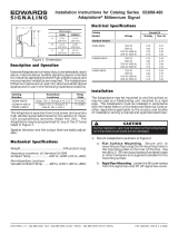
Input 2
Output 2
Input 1
Controller 1
projectio
n
module 1
projectio
n
module 2
Controller 2
Output 1
Figure 2-1
connecting Hermes DXD (schematics)

2.2 Assign ing inputs to outputs
H
ERMES DXD is operated by means of remote control, and the inputs are routed to the output via
the respective command, cf.
5.3 Switching commands.
The following schematics show the multiple possibilities for assigning an input to an output. For a
clear arrangement, the connections which can be established in parallel are indicated by gray
dashed lines.
Input 2
Output 2
Input 1
Output 1
Input 2
Output 2
Input 1
Output 1
Input 2
Output 2
Input 1
Output 1
Input 2
Output 2
Input 1
Output 1
Figure 2-2
assigning inputs to output
2.3 Remot e Control
H
ERMES DXD is controlled by a serial interface. The remote control is integrated in X Window
(see
7.3.3 User’s Manuals) and available as application for Windows NT/2000/XP (HERMES REMOTE-
C
ONTROL). The protocol is accessible for individual applications.
The general concept of remote control, i. e. cabling, connection settings and protocol are described
separately in chapter
4 Remote Control.

3 Gettin g started
This chapter describes the control elements and interfaces of HERMES DXD as well as the cabling.

3.1 Examin ing
Figure 3-1
Hermes DXD
3.1.1 The Fro nt Panel
The front panel of your HERMES DXD looks like this or similar:
1
POWERDIGITAL OUT 2DIGITAL OUT 1DIGITAL IN 2DIGITAL IN 1REMOTE OUTREMOTE IN
23 4 56 78 9 10 11
Figure 3-2
Front Panel of Hermes DXD
1 REMOTE IN
2 REMOTE OUT
3 LED: DIGITAL IN 1
4 DIGITAL IN 1
5 LED: DIGITAL IN 2
6 DIGITAL IN 2
7 LED: DIGITAL OUT 1
8 DIGITAL OUT 1
9 LED: DIGITAL OUT 2
10 DIGITAL OUT 2
11 LED: POWER
The REMOTE IN socket [1] is for plugging in the remote control cable coming from the previous device
(or the controlling PC), the
REMOTE OUT [2] for the cable leading to the next device.
The
DIGITAL IN 1 socket [4] is for connecting HERMES DXD with the graphic card of a graphical con-
troller. The DVI cable is plugged in here. If a signal is applied to
DIGITAL IN 1, the LED [3] is green,
else off.
The
DIGITAL IN 2 socket [6] is for connecting HERMES DXD with the graphic card of a graphical con-
troller. The DVI cable is plugged in here. If a signal is applied to
DIGITAL IN 2, the LED [5] is orange,
else off.
The
DIGITAL OUT 1 socket [8] is for connecting HERMES DXD with the projection unit of a Barco pro-
jection cube. If the signal of
DIGITAL IN 1 is applied to DIGITAL OUT 1, the LED [7] is green, if the sig-
nal of
DIGITAL IN 2 is applied to DIGITAL OUT 1, the LED [7] is orange.
The
DIGITAL OUT 2 socket [10] is for connecting HERMES DXD with the projection unit of a Barco
projection cube. If the signal of
DIGITAL IN 1 is applied to DIGITAL OUT 2, the LED [9] is green, if the
signal of
DIGITAL IN 2 is applied to DIGITAL OUT 2, the LED [9] is orange.
The LED POWER [11] indicates the device is switched on and operating properly. If the LED is off,
H
ERMES DXD is switched off or the internal logic control has detected an error.

LEDs allocated to the inputs:
If they are off, there is no signal present. If there is a sync signal present, the LED is
on:
Green stands for (signal present on) input (channel) 1
Orange stands for (signal present on) input (channel) 2
LEDs allocated to the outputs:
The color of the LED indicates which input (channel) is displayed:
In case it is green, input 1 is displayed via the respective output
In case it is orange, input 2 is displayed via the respective output
Color LED LED input 1 LED input 2 LED output 1 LED output 2
off No Signal present No Signal present
green Signal present - output 1 routed to
input 1
output 2 routed to
input 1
orange - Signal present output 1 routed to
input 2
output 2 routed to
input 2

3.1.2 The Bac k Panel
The back panel of your HERMES DXD looks like this or similar:
A
BC
A Main Switch
B AC In
C AC Out
Figure 3-3
The Main Switch [A] is for switching HERMES DXD on and off. If the 0 is visible on top of the switch,
the device is switched off, and it can be switched on by pressing the switch.
The
AC In socket [B] is for connecting to a power supply as specified in section 7.1.2 Power Supply.
The AC Out socket [C] is for connecting further devices (of type HERMES DXD only!) to the power sup-
ply.
AC Out is connected directly to AC In and is live as soon as AC In is connected to a power supply.
Up to max. ten HERMES DXD devices can be put on top of each other. Thus you can
group the devices into towers next to each other, e. g., in the same order as the pro-
jection cubes are arranged.
To protect HERMES DXD from overheating, the air supply openings in the case must
not be covered! If you group the devices into towers standing next to each other a
space between the devices not less than 10 centimeter must be kept!

3.2 Native device settings (default settings)
Hermes DXD has auto switch capabilities: in case there is no signal present at the input routed to an
output, the output may switch automatically to the other input. Per default, this auto switch functionality
is enabled. If desired, it can be deactivated, cf. Enabling/Disabling auto switch
Having two graphic channels connected to HERMES DXD, and none of them specified as input source,
the channel connected to
DIGITAL IN 1 is selected as signal for DIGITAL OUT 1, and the channel con-
nected to
DIGITAL IN 2 is selected as signal for DIGITAL OUT 2.
If no signal is detected on the graphic channel connected to
DIGITAL IN 1, then the graphic channel con-
nected to
DIGITAL IN 2 is selected automatically as input for DIGITAL OUT 1 instead, provided auto
switch
is enabled
If no signal is detected on the graphic channel connected to
DIGITAL IN 2, then the graphic channel con-
nected to
DIGITAL IN 1 is selected automatically as input for DIGITAL OUT 2 instead, provided auto
switch
is enabled.
After cabling is complete you can switch on the device with the main switch on the back panel.
Switching between the two graphical controllers is done by means of the remote control (see chapter
5.3
Switching commands
.
3.3 DDC C apability
H
ERMES DXD has DDC capability, i.e. it reads the timing of the connected projection module.
It is mandatory that the projection units connected to the two outputs of a Hermes
DXD are all of the same type, e.g. OverView D
HERMES DXD scans the outputs to get the timing information of the connected projection modules. As
soon as it gets a timing, the scan procedure is finished, and the detected timing information is stored and
used for both inputs!
The graphical channel connected to
DIGITAL IN 1 and the graphical channel connected to DIGITAL IN 2
during the boot procedure look up once the timing of the input and adjust their settings accordingly. To
ensure that HERMES DXD provides the timing information already when booting the controller it is rec-
ommend to first switch on H
ERMES DXD, and then switch on the controller.
Hermes DXD scans the timing of the projection module whenever a connection is
made. If the timing changes, e.g. a projector is disconnected and a different one
connected, Hermes DXD "knows" it immediately and adjusts the information stored
in DIGITAL IN 1 and DIGITAL IN 2 accordingly.
The graphic card looks up the timing information ONLY during the boot procedure.
Thus replacing a projector with a different timing requires re-booting the graphical
controller to get the correct settings!
/