
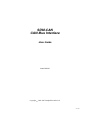
SDM-CAN
CAN-Bus Interface
User Guide
Issued 26.6.07
Copyright
©
2001-2007 Campbell Scientific Ltd.
CSL 419


Guarantee
This equipment is guaranteed against defects in materials and
workmanship. This guarantee applies for twelve months from date of
delivery. We will repair or replace products which prove to be defective
during the guarantee period provided they are returned to us prepaid. The
guarantee will not apply to:
• Equipment which has been modified or altered in any way without the
written permission of Campbell Scientific
• Batteries
• Any product which has been subjected to misuse, neglect, acts of God
or damage in transit.
Campbell Scientific will return guaranteed equipment by surface carrier
prepaid. Campbell Scientific will not reimburse the claimant for costs
incurred in removing and/or reinstalling equipment. This guarantee and
the Company’s obligation thereunder is in lieu of all other guarantees,
expressed or implied, including those of suitability and fitness for a
particular purpose. Campbell Scientific is not liable for consequential
damage.
Please inform us before returning equipment and obtain a Repair Refer-
ence Number whether the repair is under guarantee or not. Please state the
faults as clearly as possible, and if the product is out of the guarantee
period it should be accompanied by a purchase order. Quotations for re-
pairs can be given on request.
When returning equipment, the Repair Reference Number must be clearly
marked on the outside of the package.
Note that goods sent air freight are subject to Customs clearance fees
which Campbell Scientific will charge to customers. In many cases, these
charges are greater than the cost of the repair.
Campbell Scientific Ltd,
Campbell Park, 80 Hathern Road,
Shepshed, Loughborough, LE12 9GX, UK
Tel: +44 (0) 1509 601141
Fax: +44 (0) 1509 601091
Email: support@campbellsci.co.uk
www.campbellsci.co.uk


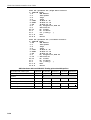
Contents
Section 1. Introduction ................................................ 1-1
1.1 General Description..............................................................................1-1
1.2 Specifications........................................................................................ 1-2
1.2.1 General Features and Specifications........................................... 1-2
1.2.2 Electrical Specifications..............................................................1-2
1.2.3 Physical Specifications................................................................1-3
Section 2. Installation .................................................. 2-1
2.1 Address Switch Configuration..............................................................2-1
2.2 Internal Jumper Settings .......................................................................2-2
2.3 Connection to the Datalogger and Power Supply.................................2-4
2.3.1 LED Status Indication.................................................................2-5
2.4 Connection to CAN-Bus....................................................................... 2-6
Section 3. Programming CR10X, CR7 and CR23X
Dataloggers to use the SDM-CAN............ 3-1
3.1 General Principles.................................................................................3-1
3.2 System Limitations ............................................................................... 3-2
3.3 The Datalogger Instruction...................................................................3-3
3.4 Advanced Programming Techniques..................................................3-12
3.4.1 Interrupts Using the I/O Connection......................................... 3-12
3.4.2 Group Trigger ........................................................................... 3-14
3.5 Program Examples..............................................................................3-14
3.5.1 Reading CAN Data ................................................................... 3-14
3.5.2 Simple CAN Data Transmission...............................................3-15
3.5.3 Building and Sending Data Frames...........................................3-16
3.5.4 Using the Interrupt Function.....................................................3-17
3.5.5 Using the Group Trigger........................................................... 3-18
Section 4. Programming CR5000 and CR9000
Dataloggers to use the SDM-CAN............ 4-1
4.1 General Principles.................................................................................4-1
4.2 Datalogger Instruction ..........................................................................4-1
4.2.1 Reading CAN Data ..................................................................... 4-2
4.2.2 Simple CAN Data Transmission.................................................4-3
4.2.3 Digital I/O Triggered CANbus Measurements ...........................4-4
4.2.4 SlowSequence Instruction...........................................................4-5
Section 5. Using the RS232 Serial Diagnostic Port... 5-1
5.1 Connecting to the RS232 User Port......................................................5-1
5.2 Diagnostic Commands.......................................................................... 5-1
5.3 Loading a New Operating System into the SDM-CAN Interface.........5-3

Appendix A. Principles of Operation ......................... A-1
A.1 Data Collection....................................................................................A-1
A.2 Frame Transmission.............................................................................A-1
Appendix B. A Summary of Data Types .................... B-1
Appendix C. Applications of the SDM-CAN on
Networks Complying with the J1939
SAE Standards ...................................... C-1
C.1 J1939 29-Bit Identifier Format ............................................................C-1
C.2 J1939 11-Bit Identifier Format ............................................................C-1
C.3 J1939 Data Frame Format....................................................................C-2
C.4 Retrieving J1939 Accelerator Pedal Position Data using a
CR9000/CR5000 (Bus Speed 250k Baud) ..........................................C-2
C.4.1 Encoding the Identifier Field Values .........................................C-2
C.4.2 Finding the Start Bit...................................................................C-3
C.5 Retrieving J1939 Accelerator Pedal Position Data using a
CR23X/CR10X (Bus Speed 250k Baud)............................................C-4
C.5.1 Encoding the Identifier Field Values .........................................C-4
C.5.2 Finding the Start Bit...................................................................C-5
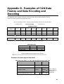
Appendix D. Examples of CAN Data Frames and Data
Encoding and Decoding ....................... D-1
Figures
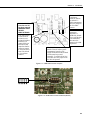
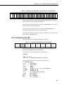
1-1 SDM-CAN CAN-Bus Interface........................................................... 1-1
2-1 SDM-CAN Internal Jumpers................................................................ 2-3
2-2 SDM-CAN Isolation enabled............................................................... 2-3
2-3 SDM-CAN Isolation disabled.............................................................. 2-4
2-4 Using the Spring Loaded Terminal Blocks (Top Option).................... 2-5
2-5 Using the Spring Loaded Terminal Blocks (Front Option).................. 2-5
Tables
2-1 Switch Position and Addresses ............................................................ 2-1
2-2 LED Status Indication.......................................................................... 2-6
2-3 CIA CAN Connector Pin Connections................................................. 2-6
3-1 Typical Settings of the CAN Speed Parameters................................... 3-5
5-1 RS232 Pin Out...................................................................................... 5-1
C-1 Mapping of the J1939 Fields into a 29-Bit Identifier..........................C-1
C-2 Mapping of the J1939 Fields into a 11-Bit Identifier...........................C-1
C-3 J1939 Data Frame format ....................................................................C-2
C-4 Mapping of J1939 Identifier Field Values into a 29-Bit Identifier......C-3
C-5 Accelerator Pedal Position Value Byte Number..................................C-3
C-6 Mapping of J1939 Identifier Field Values into a 29-Bit Identifier.......C-5
C-7 Accelerator Pedal Position Value Byte Number...................................C-5

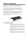
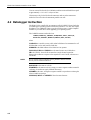
Section 1. Introduction
The SDM-CAN interface is designed to allow a Campbell Scientific datalogger to sample data
directly from a CAN-Bus communications network and thereby allow such data to be stored
along with, and in synchronisation with, other data values measured directly by the
datalogger.
To use the SDM-CAN device it is assumed that you have a full working understanding of the
CAN network you wish to monitor. While there are moves to standardise CAN networks for
different types of applications, the SDM-CAN device is designed to be as generic as possible
thus allowing use in a wide range of applications, including research and development, where
you may be working outside the normal standards.
As a result you will need to know details of the electrical configuration of the network, the
speed and CAN standard in use, plus knowledge of the identifiers of the data packets that are
of interest and the way in which data is encoded within those packets at the binary level. This
information may need to be obtained from the designers of the network, from propietary
documentation or from the standards to which a network claims to comply.
Campbell Scientific cannot provide full technical support in the understanding and decoding
of data on all types of CAN networks.
Figure 1-1 SDM-CAN CAN-Bus Interface
1.1 General Description
The SDM-CAN forms an intelligent interface between a Campbell Scientific
datalogger and a CAN-Bus communications network. The SDM-CAN is
configured by the datalogger under the control of the user’s datalogger program.
By this process the SDM-CAN can capture data on the CAN-Bus and filter out
packets of interest to the user. Within each data packet the device is able to read
one or more data values and convert them to numeric values compatible with the
normal data stored by the datalogger.
The SDM-CAN will act as a passive listen-only device with its transmitter
disabled in hardware. Alternatively it can be configured to send/respond to
Remote Frame Requests, allowing it to poll remote devices for data. Data packets
can also be constructed to allow it to send data out onto the CAN-Bus so it then
acts as a sensor itself.
Data is transferred between the SDM-CAN interface and the datalogger using
Campbell Scientific’s high speed SDM communications protocol. This protocol
allows the SDM-CAN to be used in parallel with other SDM devices (including
1-1

SDM-CAN CAN-Bus Interface User Guide
other SDM-CAN interfaces) which might, for instance, be on other CAN-Bus
networks in the same vehicle.
In addition to connectors to the CAN network and the datalogger, an RS232 port
is also provided both for diagnostics and operating system upgrades.
1.2 Specifications
1.2.1 General Features and Specifications
• Uses Campbell Scientific’s SDM communication protocol to communicate
with the datalogger via a three wire serial multidrop connection. Support is
planned for CR10X, CR23X, CR7, CR5000 and CR9000 dataloggers.
• Up to 16 units can be used per datalogger, with the modules’ SDM address set
by rotary switch.
• CAN 2.0A and 2.0B active and passive modes supported
• Up to 1Mbaud max data rate. Standard baud rates supported are 1M, 800K,
500K, 250K, 125K, 50K, 20K and lower. Other non-standard baud rates may
be possible – please contact Campbell Scientific.
• Receive and transmit up to 128 different data values from up to 128 CAN
ID’s.
• Build and send a CAN data frame.
• Send Remote Frame Requests.
• Send data frame in response to an external Remote Frame Request.
• Supports a number of power down modes to allow power saving in power
critical applications.
• All configuration of the interface is specified within the user’s datalogger
program.
• LED status flash at power up
• Additional I/O port for signalling to the datalogger that data is available,
e.g. using an interrupt function.
• Has a 9 pin, DCE RS232 port with auto baud rate detection (1200 to
115200) for diagnosis and operating software download.
• Standard operating temperature range (tested), -25ºC to +50ºC. Can be used
over an extended temperature range – contact Campbell Scientific for details.
• High speed block mode for fast data collection.
• Buffer assisted burst mode for capturing back to back high speed CAN data.
• Buffer’s support data frame filtering and triggering.
1.2.2 Electrical Specifications
• Power supply range: 7 to 26V DC.
• Optional (switch selectable) galvanic isolation between the datalogger and the
CAN-Bus. The minimum isolation breakdown is 50V – this barrier is for
signal isolation only, i.e. it is not a safety barrier.
• Hitachi H8S,16 bit CPU clocked at 10MHz.
• Uses the latest Philips SJA1000 CAN controller clocked at 16MHz.
• CAN-Bus physical interface using Philips PCA82C251 driver for 1Mbaud
capability, for use in 12V or 24V systems.
• CAN-Bus physical connection conforms to CIA draft standard 102 version 2,
9 pin D connector. (The interface will differ from this standard only with
respect to pin 9, which outputs 5V DC instead of 7-13V DC.)
1-2

Section 1. Introduction
• A 3 way, unpluggable screw terminal block for CAN High, Low and G also
provided.
• Transmit and acknowledge to CAN-Bus can be disabled by a hardware
jumper for safety reasons, e.g. for in-vehicle, listen only monitoring.
• I/O terminal used for interrupts is pulled low by a 100Kohm resistor and is
driven to 5V via a 1Kohm impedance when an interrupt is pending.
1.2.2.1 Power Consumption
• Typical active current in self-powered, isolated mode with the CAN-Bus in
the recessive state: 70mA. (this is when the SDM-CAN is not transmitting).
• Typical active current in self-powered, isolated mode with the CAN-Bus in
the dominant state: 120mA (this is when data is being transmitted from the
SDM-CAN device).
Where the DC-DC converter is not used, and power is provided to the isolated
CAN driver circuits by an external source, the current drain by the SDM-
CAN is approximately 50 mA lower than the figures quoted above.
• Typical active current, non-isolated with the CAN-Bus in the recessive state:
30mA.
• Typical active current, non-isolated with the CAN-Bus in the dominant state:
70mA
• Typical Standby Current with or without isolation is less than 1mA (in this
mode the CAN hardware is turned off so the module cannot wake on receipt
of CAN data). Current consumption increases to typically 50 mA during
periods of communication to the datalogger or when the RS232 port is active.
1.2.3 Physical Specifications
• Maximum dimensions: width 175mm, height 100mm, depth 23mm (without
mounting brackets).
• Weight: 300g without mounting brackets.
• The device can be vertically mounted with all the connectors on the top
surface.
• The SDM address switch is on the right hand side.
• Fittings are available to allow vertical mounting in the CR9000 or on
enclosure chassis plates.
1-3


Section 2. Installation
The SDM-CAN can be mounted in a normal card slot of a CR9000 (using optional special end
brackets), on a chassis plate (using the standard brackets supplied) or can be left free-
standing.
CR9000 and CR7 dataloggers require optional SDM connection kits and all dataloggers may
require an upgrade to a version of operating system which supports the SDM-CAN interface.
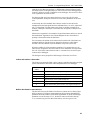
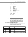
2.1 Address Switch Configuration
Before installing the SDM-CAN, set the SDM address switch to ensure that the
interface has a unique address on the SDM bus, and that the address is set to
match the commands in the datalogger program relevant to each interface.
The SDM address switch can be set to 1 of 16 addresses. The factory-set address
is 00. Table 1 shows switch position and the corresponding address. The Base 4
address is also shown, as this is the address entered in the datalogger program.
Please see Section 3 before using address F (33 base 4) as this address is often
used as a ‘group trigger’ to synchronise measurements by several SDM devices.
The switch is positioned on the right-hand side of the case, so you may have to
remove the mounting bracket to gain access to this switch.
Table 2-1 Switch Position and Addresses
Switch Setting Base 4 Address
0 00
1 01
2 02
3 03
4 10
5 11
6 12
7 13
8 20
9 21
A 22
B 23
C 30
D 31
E 32
F 33
2-1

SDM-CAN CAN-Bus Interface User Guide
2.2 Internal Jumper Settings
The SDM-CAN interface is fitted with a number of jumpers which configure the
connection to the CAN network.
Prior to setting these jumpers you need to give some consideration on how best to
connect the SDM-CAN interface to the network:
1) Decide whether the CAN network is already terminated, or if the SDM-CAN
needs to provide termination. In most instances the network will already be
terminated and so the default setting is no termination.
2) Decide whether to operate the SDM-CAN in a mode where it is isolated from
the CAN network. This is the ‘safest’ mode of operation as it minimises the
risk of corrupting the CAN data by the formation of grounds loops which
could inject noise onto the CAN-Bus. The default setting is to run in isolated
mode.
3) If running in isolated mode decide whether the SDM-CAN will supply power
via a built-in DC-DC converter for the isolated CAN interface components, or
whether power will be sourced from an external supply. Using a converter
adds 40-50mA to the power consumption of the SDM-CAN when it is active.
However, if a converter is not used, power must be provided from elsewhere
(see below). The default setting is for the converter to be OFF, although for
many applications you may need to turn it on once you have considered the
implications for your power supply.
4) Decide whether the transmit functions of the SDM-CAN interface need to be
enabled in hardware. The disabled mode of operation is the safest, especially
in vehicle applications, as it avoids the risk of the SDM-CAN sending bad
data onto the CAN network. However, in some modes of operation,
transmission is obligatory e.g. to let the SDM-CAN request data, acknowledge
data or to transmit data onto the bus. If transmission is to be enabled, the
relevant jumpers need to be changed. Additionally transmission must be
enabled by sending the SDM-CAN an instruction which both enables and
specifies the method of transmission. See Section 3.3, data type 32, below.
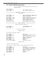
Access to the jumpers requires the removal of the lid of the SDM-CAN. Please
follow anti-static precautions during the removal of the lid and also when
changing the jumpers. Refer to Figure 2-1 for details of the jumper positions.
Labels are also provided in white writing on the circuit board.
If white jumper block not fitted then refer to Figure 2-2 for isolation enabled and
Figure 2-3 for isolation disabled.
2-2

Section 2. Installation
Transmission of
CAN data is
hardware
disabled
by default. To
enable transmission,
move the jumper to
the TX enable
position.
SDM-CAN PCB
Once the case lid
has been removed.
OBSERVE ANTI-
STATIC
PRE
Figure 2-1 SDM-CAN Internal Jumpers
Figure 2-2 SDM-CAN Isolation enabled (default)
This jumper block
is used to select
isolated or non-
isolated CAN-Bus
interface. The
jumper block can
be removed and
rotated so that the
red bar is nearest
to the mode arrow
head. The default
is for isolation
enabled.
The CAN-Bus
termination
impedance is
disabled by default.
If you need the bus
to be terminated,
then move the
jumper to the 120R
IN position.
C
A
U
TIONS.
The DC-DC converter is off by
default. This will reduce power
consumption from the +12V
supply but means that the isolated
circuits must be powered
externally. To enable the DC-DC
converter move the jumper to the
DC-DC ON position.
2-3

SDM-CAN CAN-Bus Interface User Guide
Figure 2-3 SDM-CAN Isolation disabled
2.3 Connection to the Datalogger and Power Supply
To allow communication between the SDM-CAN and a datalogger, firstly connect
it to the datalogger’s SDM port, and then connect to a 12V power supply. Both the
datalogger and the SDM-CAN 12V power supply must share a common ground.
The SDM port is provided in different ways on different dataloggers:
CR10X and CR23X – use the C1, C2 and C3 control ports.
CR7 – a special SDM terminal block is provided as part of the SDM upgrade kit.
This terminal block is fitted on a small module adjacent to the 9 way ‘Serial I/O’
connector on the front of the 700 control module. The connections are labelled C1,
C2 and C3.
CR5000 – use the port connections labelled SDM-C1, SDM-C2 and SDM-C3.
CR9000 – connections are made via the 9 way, ‘CSI Serial I/O’ connector on the
9080 PAM card. Pins 6, 7 and 8 are used as C3, C2 and C1 respectively. Pin 2 is
ground. Campbell Scientific offers connection modules for this port which allow
access to the SDM function as well as retaining normal function of the serial port,
please contact your local sales office for further details.
The SDM-CAN requires a nominal 12V power supply connection (7-26V) rated
at 150mA. Normally the datalogger supply can be used for this feed. A connection
to ground is also required. If the 12V supply is separate from the datalogger, both
the ground of the supply and datalogger must be connected together.
The SDM and power connections are made to a black terminal block on the left-
hand side of the SDM-CAN interface. This terminal block has special spring
loaded terminals which are simple to use and highly resistant to loosening in high
vibration environments. To open the terminal simply insert the tip of a small flat
blade screw driver (3mm width) into the rectangular hole above the circular
terminal hole. Push in the blade of the screwdriver until the spring is released and
the terminal opens. Insert the pre-stripped wire and then remove the screwdriver.
See Figure 2-4. If space is limited, as when the unit is mounted in an enclosure
etc., the screwdriver can be inserted into the front of the terminal block to push
open the spring, as shown in Figure 2-5.
2-4

Section 2. Installation
Figure 2-4 Using the Spring Loaded Terminal Blocks (Top Option)
Figure 2-5 Using the Spring Loaded Terminal Blocks (Front Option)
Where you need to install more than one wire in a single terminal connector, use
only stranded wires and twist the wires together before inserting them in the
terminal. This type of terminal is not suitable for use with multiple solid core
wires unless the wires are joined externally, e.g. using a ferrule.
Route the wires from the SDM-CAN interface to the datalogger connections using
the shortest route. Avoid running them near cables which could cause noise
pickup. In noisy environments use low capacitance signal cable with an overall
foil screen, connecting the screen to the datalogger power ground.
Where multiple SDM devices are in use connect them in parallel to datalogger
SDM ports, making sure each device has a unique SDM address. Ensure that the
maximum cable length between the datalogger and the SDM-CAN does not
exceed 3 metres.
An additional I/O terminal is provided on the SDM-CAN for use with dataloggers
which support interrupt driven logging events. This might typically be used to
enable the rapid capture of time critical CAN data, where the I/O port can be used
to indicate to the datalogger that data has been captured and is available for
immediate collection (see below). In most applications this function will not be
used and the terminal need not be connected. Where it is required, it should be
connected to a digital input on the datalogger.
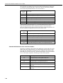
2.3.1 LED Status Indication
When power is applied to the SDM-CAN the red ‘STATUS’ LED will flash to
indicate the current status of the unit as a result of the power-up checks.
2-5

SDM-CAN CAN-Bus Interface User Guide
If the LED flashes once, the module has passed all power-up tests and should
operate correctly. The other flash sequences are shown below. Problems with the
operating system can normally be fixed by reloading the operating system.
Please contact Campbell Scientific if you are unable to resolve the problem.
Table 2-2 LED Status Indication
Number of
flashes
Indication
1 SDM-CAN is ok.
2 OS signature bad.
10 OS downloaded has failed.
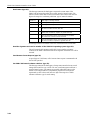
2.4 Connection to CAN-Bus.
The physical connection to the CAN-Bus is achieved by one of two methods
which is by either the 3 way un-pluggable screw terminals or the 9 pin ‘D’ plug
which conforms to CIA draft standard 102 version 2.
The basic connections of the CAN-Bus to the three-way terminal are CAN High,
CAN Low and 0V ground reference. The 3 way screw terminal is marked as
‘G H L’ on the SDM-CAN case, where G=Ground, H=CAN High, L=CAN Low.
The CIA, 9 pin, ‘D’ connector pin configuration is shown in Table 2-3.
Table 2-3 CIA CAN Connector Pin Connections
Pin Function
1 Reserved, NOT INTERNALLY CONNECTED.
2 CAN Low.
3 CAN Ground.
4 Reserved, NOT INTERNALLY CONNECTED.
5 CAN Shield.
6 CAN Ground.
7 CAN High.
8 Reserved, NOT INTERNALLY CONNECTED.
9 CAN +5volts. Input or output (see text).
If the SDM-CAN hardware is configured (in either isolated or non-isolated mode)
with the DC-DC converter ON, then Pin 9 of the 9 pin ‘D’ connector will provide
+5V +/-10% at up to 40mA to any external device. If isolation is enabled and the
DC-DC converter is set to OFF then this pin acts as an input for an external power
supply capable of providing +5volts +/-10% at up to 100mA to provide power to
the isolated circuitry of the SDM-CAN.
The 3-way terminal block and CIA connector are connected in
parallel internally and are not two separate connections to different
CAN interfaces.
NOTE
2-6

Section 2. Installation
Please refer to the documentation for your CAN network to check the preferred
method of connection. For many applications various standards will apply giving
recommended practises for connection. Apart from the choice of connector some
standards recommend different ways of ‘tapping’ into CAN networks and also
recommend maximum lengths for ‘T’s or ‘stubs’ off the network. For instance, at
the highest baud rate of 1Mbit/s, ISO11898 recommends a maximum bus length
of 40 m and a maximum stub length of 0.3 m. These lengths increase significantly
at lower bit rates.
As discussed above you also need to consider:
• If the SDM-CAN should terminate the network
• If it should be configured in isolated mode
• If transmission should be enabled
• The source of power for the isolation hardware.
2-7


Section 3. Programming CR10X, CR7
and CR23X Dataloggers to use the
SDM-CAN
This section describes the programming methods used for the above dataloggers to configure
and use the SDM-CAN Interface. This section also covers general principles and techniques
which are relevant to the other dataloggers,
3.1 General Principles
The SDM-CAN interface is controlled by instructions that the user enters in the
datalogger program. For the dataloggers covered by this section the Program
Instruction is number P118. Full details of the instruction are given below. This
sub-section has been written to introduce the parameters of Instruction P118 and
how they allow you to control the different operations of the SDM-CAN.
The initial function is to configure the SDM-CAN interface when the datalogger
program is compiled. At this stage, the datalogger analyses the P118 parameters
used by the program and sends the relevant commands to the SDM-CAN to
configure it to perform appropriate tasks.
The most common configuration task, at compile time, is to set up the SDM-CAN
to instruct it to filter out only the data frames of interest from all data ‘passing on
the bus’.
The other configuration task done at this point is to specify the speed at which the
CAN-Bus is to operate. It is important to ensure the parameters which define the
speed are set correctly and all instructions have the same values entered for these
parameters otherwise either no data will be received, or you risk corrupting data
on the bus, if the SDM-CAN is enabled for transmission.
The next common function is to read data back from the SDM-CAN, to decode it,
and to store it in input locations once the program is running. A single entry of
P118 in the program can both configure the SDM-CAN during program
compilation and also cause data to be read back from the SDM-CAN when that
instruction is executed during normal program execution.
Similarly there is also a function which is used to send simple data from the
datalogger input locations onto the CAN-Bus via the SDM-CAN. Again a single
call of P118 can both configure and then transmit the data when the program is
running.
A more complicated version of this function is also possible where multiple P118
instructions are used to build a transmit data frame within the SDM-CAN, made
up of a series of fixed or variable data values from input locations. A subsequent
P118 is used to instruct the SDM-CAN to transmit the frame either immediately or
in a response to a remote frame request from another device.
Finally there are some special functions normally achieved by a single a call of
P118. One such function is used to change internal ‘switches’ within the SDM-
CAN which control its mode of operation, e.g. power mode, response to failed
transmissions etc. Similar functions also allow you to read back the settings of
these ‘switches’ into input locations and also to read and/or reset the number of
CAN errors detected and to also determine the general status of the SDM-CAN
interface.
3-1

SDM-CAN CAN-Bus Interface User Guide
3.2 System Limitations
The SDM-CAN interface, in combination with a datalogger, has some limitations
of which you need to be aware:
1) Memory Allocation and P118
Firstly, as discussed above, when the datalogger compiles a program with
P118 in it, it sends commands to the SDM-CAN instructing it what to do at
run time. When it does this the SDM-CAN allocates some of its memory (a
‘bin’) for each call of P118 in the program. Appendix A discusses the
operation of these bins and other buffers in the SDM-CAN in more detail.
However, most users only need to know that there is a limit of 128 bins in the
SDM-CAN thus constraining the number of instances of P118 for any one
SDM-CAN to 128.
It is, of course, possible to have several SDM-CAN devices connected to the
datalogger(s), each with separate SDM addresses, and each with up to 128
calls of P118.
2) Data Capture Limitations
Another limitation is the capability of the overall speed at which the
datalogger can pick up and transfer data values back to its memory. These
limitations do not arise within the SDM-CAN interface itself, as it uses a high
speed CAN interface along with a fast microprocessor. Data can therefore be
captured off the CAN-Bus at close to the maximum bus loading at the
maximum baud rate. However, the limitations arise from the datalogger itself,
both in terms of its capability to call P118 often enough (especially when
making other measurements) and also in its capability to transfer the data from
the SDM-CAN back into its memory over the SDM communications port.
The exact throughput possible is determined by a very complicated
combination of variables, including the speed of the datalogger in question,
the program it is running, how many SDM devices are in use and, to a lesser
degree, other tasks it is running, e.g. communications activity.
In practise, for fast data, it will not be practical to capture every single data
packet. However, the SDM-CAN will be used to sample the last reading it
received on the CAN-Bus before the datalogger requests data.
If a new data value has not been captured from the CAN-Bus since the last
value was transferred to the datalogger, the SDM-CAN can either be set to
always return the previous value captured (default) or it can be configured
(see the internal software switch settings below) to return the standard out of
range value to the datalogger, i.e. –99999 if the value has already been read.
This value will also be returned in the event of other errors including
communication errors between the datalogger and SDM-CAN.
Data stored in packets on the CAN-Bus can be encoded in a number of
different ways. The SDM-CAN itself can cater for many different types of
data, but there are some limitations imposed by the way in which the data is
stored in the datalogger. The prime limitation is that data read into the
datalogger is first converted into a 4 byte floating point format which can only
resolve, at most, 23 bits, or roughly 7 digits, of the decimal equivalent of any
number stored. Furthermore, when data is stored to final storage, the
resolution is truncated again to either 4 or 5 digits (with the exception of the
CR5000/9000 dataloggers which also support storage in IEEE4 format).
To avoid over-running the datalogger’s internal floating point resolution, the
maximum length of integer that the SDM-CAN can send or receive is
therefore limited to 16 bits. This limited resolution can cause problems when
reading CAN data where data is encoded as 32 or 64 bit integers.
3-2
Page is loading ...
Page is loading ...
Page is loading ...
Page is loading ...
Page is loading ...
Page is loading ...
Page is loading ...
Page is loading ...
Page is loading ...
Page is loading ...
Page is loading ...
Page is loading ...
Page is loading ...
Page is loading ...
Page is loading ...
Page is loading ...
Page is loading ...
Page is loading ...
Page is loading ...
Page is loading ...
Page is loading ...
Page is loading ...
Page is loading ...
Page is loading ...
Page is loading ...
Page is loading ...
Page is loading ...
Page is loading ...
Page is loading ...
Page is loading ...
Page is loading ...
Page is loading ...
Page is loading ...
Page is loading ...
Page is loading ...
Page is loading ...
Page is loading ...
Page is loading ...
Page is loading ...
Page is loading ...
Page is loading ...
Page is loading ...
Page is loading ...
Page is loading ...
Page is loading ...
Page is loading ...
Page is loading ...
Page is loading ...
Page is loading ...
Page is loading ...
Page is loading ...
Page is loading ...
Page is loading ...
Page is loading ...
-
 1
1
-
 2
2
-
 3
3
-
 4
4
-
 5
5
-
 6
6
-
 7
7
-
 8
8
-
 9
9
-
 10
10
-
 11
11
-
 12
12
-
 13
13
-
 14
14
-
 15
15
-
 16
16
-
 17
17
-
 18
18
-
 19
19
-
 20
20
-
 21
21
-
 22
22
-
 23
23
-
 24
24
-
 25
25
-
 26
26
-
 27
27
-
 28
28
-
 29
29
-
 30
30
-
 31
31
-
 32
32
-
 33
33
-
 34
34
-
 35
35
-
 36
36
-
 37
37
-
 38
38
-
 39
39
-
 40
40
-
 41
41
-
 42
42
-
 43
43
-
 44
44
-
 45
45
-
 46
46
-
 47
47
-
 48
48
-
 49
49
-
 50
50
-
 51
51
-
 52
52
-
 53
53
-
 54
54
-
 55
55
-
 56
56
-
 57
57
-
 58
58
-
 59
59
-
 60
60
-
 61
61
-
 62
62
-
 63
63
-
 64
64
-
 65
65
-
 66
66
-
 67
67
-
 68
68
-
 69
69
-
 70
70
-
 71
71
-
 72
72
-
 73
73
-
 74
74


Ask a question and I''ll find the answer in the document
Finding information in a document is now easier with AI
Related papers
-
Campbell Scientific SDM-CAN Owner's manual
-
-
Campbell Hausfeld Network Card SDM-CVO4 User manual
-
-
Campbell Scientific SDM-CD16ACA 16-Channel AC/DC Relay Controller Owner's manual
-
-
-
-
-
Other documents
-
-
-
-
-
-
-
-
-
-