Page is loading ...

DIESEL SPACE HEATER-SERVICE MANUAL
1. CONTROLS AND COMPONENTS
2. FLAME CONTROL CYCLES
3. MAINTENANCE SCHEDULE
4. REPAIR PROCEDURES
1. FAN MOTOR ASSEMBLY
2. FUEL FILTER ASSEMBLY
3. FUEL PUMP ASSEMBLY
4. ELECTRIC PANEL ASSEMBLY
5. AIR PRESSURE SWITCH
6. COMBUSTION HEAD ASSEMBLY
7. COMBUSTION CHAMBER
5. TROUBLESHOOTING GUIDE
6. WIRING DIAGRAMS
7. TECHNICAL SHEETS
INDEX
HS2000ID, HS3000ID
HS3500DF, HS6000DF
L-S 102.00-BM
WARNING
The operations described in this booklet must be carried out by qualied and instructed personnel only.
Incorrect maintenance may result in improper operation and serious injury.
1
!

1 COMBUSTION CHAMBER
2 BURNER ASSEMBLY
3 NOZZLE
4 FUEL VALVE
5 DIESEL PUMP
6 MOTOR
7 FAN
8 FUEL FILTER
9 FUEL CIRCUIT
10 FUEL TANK
11 FUEL TANK PLUG
12 DRAIN PLUG
13 RESET BUTTON/LAMP OF
CONTROL FLAME
14 MAIN SWITCH
15 ROOM THERMOSTAT PLUG
16 CONTROL LAMP
17 POWER CORD
18 OVERHEAT THERMOSTAT
19 AIR PRESSURE SWITCH GAUGE
(LOW PRESSURE SIDE)
20 AIR PRESSURE SWITCH GAUGE
(HIGH PRESSURE SIDE)
21 FLAME DETECTOR (PHOTOCELL)
22 STACK
1. CONTROLS AND COMPONENTS
INDIRECT HEATER WITH STACK:HS2000ID & HS3000ID
DIRECT HEATER WITHOUT STACK:HS3500DF & HS6000DF
CONTROL PANEL
2
13
16
17
1514

3
CONTROL SYSTEM
The heater has all operational controls located in a watertight control panel mounted on the lateral side of the unit.
The control panel consists of:
•a3-positionswitchforheatingfunction:normaloperation,stoporthermostatoperation
•plugtoconnectaremoteroomthermostat
•powercord
•highvoltagetransformerthatgeneratesasparktoignitetheame
•controlameboxtohandlestarting/runningcycle(seeparagraph2.).
Thecontrolameboxisequippedwithareset
Thecontrolsystemutilizes:
•asafetyshutoffswitchthatisanoverheatthermostatshuttingdowntheunitifthetemperatureofcombustion
chamberandoutletairexceedthemaximumallowedlevel
•anairpressureswitch,thatstopstheunitiftheairowisnotsufcientforcombustion
•aamedetector,thatisaphotocellmonitoringconstantlytheamepresenceanditsintegrity
•apairofignitionrodstocreatetheignitionspark
FUEL SYSTEM
Thefuelsystemconsistsof:
•fueltank,thatissteel,corrosionproof
Thefueltankhasadrainpluglocatedunderneathittoallowdischargeofresidualfuelbeforecleaning.
•fuellter
•fuelpump.Ascrewttedonthefuelpumpallowstheadjustmentoffuelpressuresetting
•fuelON/OFFsolenoidvalve
•duringnormaloperationthevalveisopenandthepressurizedfuelowstothenozzlewhereitis
atomized,mixedwithprimarycombustionairandignitedbytheelectrodespark
•duringabnormaloperation(seeparagraph2.)theamecontrolunitclosesthefuelsolenoidvalveand
the unit stops.
•fuelcircuit,includingsuctionandreturnhosesfromfueltanktofuelpumpandhighpressuremicrohosefromfuel
pumptonozzle
•burnerhead
•nozzle
COMBUSTION CHAMBER
For indirect heater it consists of:
•theinternalcombustionchamber(stainlesssteel)thatcontainingtheamesand
•theexternalhighefcientheatexchanger(aluminatedsteel),thatleadssmoketochimney/stack.
Fordirectheateritconsistsoftheinternalcombustionchamber(stainlesssteel),thatcontainingtheamesand
exchangesheatwiththemainairowstream.
BURNER HEAD
Theburnerheadistheassemblythatdeterminesthecorrectmixingofcombustionairandfuelinsidethecombustion
chamberanditconsistsof:
•Fuelnozzle
•Nozzlesupport
•Flamediffuser
•Airopeningbafe:ascrewttedontheburnerheadallowstheadjustmentofcombustionairsetting
•Ignitionelectrodes
•Flamedetector
FAN - MOTOR ASSEMBLY
Theelectricmotordrivesthefuelpumpassemblyandafanwhichblowsairinsideandaroundcombustionchamber.

4
2. FLAME CONTROL RUNNING / FAILURE CYCLE
Theamecontrolunitstartsthesequenceofoperationafteraheatingrequest(normaloperationorthermostatoperation)
and it consists of the following steps:
•Self-test(lessthan3s):self-checkofelectronicsefciency;
•PurgingtimeTP(20seconds):fanmotorandignitiontransformeraresimultaneouslyswitchedonwhilethefuelvalve
remainsclosedtoeliminateanyfuelorunburntresidual.
Duringthepurgingstage,theamesignalisconstantlymonitoredforanykindoffailureleadingtocombustionprevents
theburnerignition.
Incaseofheatingrequestoff(roomthermostatoff),thecontrolunitgoestostand-byposition.Thedeviceremainsin
thisstatustillclosingoftheroomthermostat;
•Safetytime(5seconds):attheendofthepurgingtimeTP,thefuelvalveisswitchedonandopensthefueltothe
nozzle.
IncaseofamedetectionfailurebytheendoftheTSsafetytime,thecontrolunitgoestolockout,andthefanmotor,
theignitiontransformerandthefuelvalvearede-energized,whilethelockoutsignalisenabled.
Otherwise,attheendoftheTSsafetytimethecontrolunitdisablestheignitiontransformerandgoestorunning
position.
•AttheendoftheTSsafetytimethecontrolunitkeepstheignitiontransformeroperatingforabout30s.
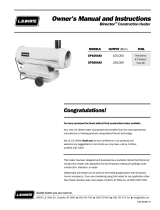
2.1 STARTING CYCLE
2.2 SHUT OFF CYCLE
Whentheheatingrequest(normaloperationorthermostatoff)opens:
•fuelvalveandignitiontransformerareswitchedoffandtheamelightsoff;
•burnerfanoperatesa90spost-purgeventilation
Restoringtheheatingrequestcausesthepost-purgetobeinterruptedandthestartingcycletobeperformed.
Room thermostat
Reset Lamp
Photocell
Fuel Valve
Ignition Transformer
Burner Fan
90 s
Room thermostat
Reset Lamp
Photocell
Fuel Valve
Ignition Transformer
Burner Fan
TP 20 s TS 5 s
30 s

5
2.3 FLAME FAILURE DURING STARTING CYCLE
IfduringthesafetytimeTS,thephotocellmonitorsaamefailure(signaltophotocellbecomeslowerthanminimum),at
theendofsafetytimetheunitgoesinlockoutcondition:
•burnerfan,ignitiontransformerandfuelvalvearede-energized;
•alarmlamponrestbuttonbecomesred
Unitcanre-startonlyifpressingtheresetbutton
2.4 EXTRANEOUS LIGHT OR FLAME DURING PRE-PURGE TIME TP
Ifduringthepre-purgetimethephotocellmonitorsanyresidualamethentheunitgoesinstand-bycondition:
•burnerfangoesontopurgingcombustionchamber
•fuelvalveandignitiontransformerarede-energized
•resetlampisoff;
Room thermostat
Reset Lamp
Photocell
Fuel Valve
Ignition Transformer
Burner Fan
TP 20 s
Room thermostat
Reset Lamp
Photocell
Fuel Valve
Ignition Transformer
Burner Fan
TP 20 s TS 5 s

6
2.5 FLAME FAILURE DURING RUNNING STATUS (ONE TRIAL RECYCLING)
Incaseofamefailureinrunningstatus,theamecontrolunitmakeonetrialrestartingtheunit.
Ifthereasonofamefailureisconrmed,thentheunitstopsinlock-outmode,andtheresetlampbecomesred.
2.6 RESET LAMP COLOR
WARNING
Theresetbuttonmayhavedifferentcolours:
• lightoff:unitisinstand-bystatus,waitingforheatingrequest.
• steadyorangelight:functionnotactive
• steadygreenlight:unitisworkingnormally(startingcycleorworkingcycle)
• steadyredlight:theheaterstopspermanentlyinlock-outstatusandcanrestartonlyifresetbuttonis
pressed.
Room thermostat
Reset Lamp
Photocell
Fuel Valve
Ignition Transformer
Burner Fan
TP 20 s TS 5 s
90 s
!

7
3. MAINTENANCE SCHEDULE
Periodicmaintenanceoftheheaterisnecessarytoensureproperperformanceandtopreventfailuresanditshallbe
performedatthefollowingperiodicintervals:
• Daily maintenance
i.Inspectairinlet/airoutletandexhauststack,removedebrisifany
ii.Ifanyairhoseisinstalled,secureit.Minimizebendsandkeepsductsstraight
iii.Verifyfueltankisfull
iv.Verifythatexhauststackisproperlyinstalled
• Weekly maintenance
i.Disassemble,inspectandcleanfuellterwithcleanfuel
ii.Removetopcoverandcleanthemotor,fanbladeandtheinteriorshell
iii.Inspectthefuelhoseassemblyandcheckforanyleaks
• 6 months maintenance
i.Disassembleburnerhead
1.Inspectandcleanburnerdiffuser
2.Inspectandreplacenozzleasnecessary
3.Cleanignitionelectrodesandadjustsettings
4.Checkaircombustionsetting
ii.Checkoverheatthermostat
iii.Inspectandcleanthecombustionchamber
iv.Openelectricboard,inspectelectricalcomponentsandcheckconnections
v.Checkfuelpressuresettingoffuelpump
vi.Inspectandtesttheburner

8
4. REPAIR PROCEDURES
WARNING
Before carrying out any maintenance operation the heater must be disconnected from power supply.
Refer to instruction manual to fully stop the heater. Therefore:
• Stop the machine as instructed
• Turn off the on/off switch on the main electric switchboard
• Wait until the heater has cooled.
Never service heater while it is plugged in, operating or hot.
Severe burns or electrical shock can occur.
1) FAN MOTOR ASSEMBLY
a) Tocleanthefanbladesandmotor,carryoutthefollowingprocedure.
i)Removetheairinletgrille(a)byremovingfourscrewsthatsecureittothemachine.
ii)Removethetopcoveraccesspanel(b)byremovingscrews
iii)Inspectand,ifnecessary,cleanthemotorusingcompressedair,beingcarefullynottodirecttheairjettothe
airpressureswitchgauge(c)(thepressureswitchcouldbedamaged)
iv)Cleanthefanbladesusingastiffbrush.
v)Reinstalltheinternalaccesspanel.
vi)Reinstallthefangrille.
!
c
b
a

9
b)Toreplacethefanbladeandtheelectricmotor,carryoutthefollowingprocedure.
i)Removetheairinletgrille(a)byremovingfourscrewsthatsecureittothemachine.
ii)Loosenthescrew(d)onthefanhub
iii)Extractthefanbladesandreplacewithanewonerespectingbladesorientation
iv)Removethetopcoveraccesspanel(b)byremovingfourscrews
v)Loosenthreeallenscrews(e)onthefuelpumpcasing(besurenottoremovethescrews)
vi)Removefuelpumpfromelectricmotorandkeepplasticcouplingfornextreassembly
vii)Loosenandremoveeightscrews(f)thatxthemotoronthemotorange
viii)Openmainelectricboardonside/frontoftheheater
ix)Tracetheelectricmotorpowercordsanddisconnectthethreewires(white,black,green)fromcontrolpanel
x)Positionanewmotoronthemotorangeandreassembleeightscrews(f)toxit
xi)Checkalignmentofthemotortotheheateraxisandtighteneightscrews(f)onmotorange
xii)Reassemblefuelpumponelectricmotorbeingsurethatplasticcouplingisaligned
xiii)Tightenthreeallenscrews(e)
xiv)Positionfanbladeonthemotorshaftbeingsurethereisnointerferencewithanypartswhenrotating
xv)Tightenscrew(d)andcheckfreerotationofthefanblades
xvi)Reinstallthefangrilleandthetopcover.
e
f
d

2) FUEL FILTER ASSEMBLY
a) Toclean/replacethepre-heatedtypefuellter,carryoutthefollowingprocedure.
i)Removethescrew(a)thatsecuresthecovertothehousingandremoveo-ring(b)
10
ii)Usingasuitablecontainer,collectthefuelwhenremovingfromthefuellterassembly
iii)Removethefuelcell(c)andwashitwithcleandieseloil
iv)Ifnecessaryreplacethefuellter(c)
v)Ifnecessarytoreplacetheheatingelement,loosenthenut(d)andremovetheelectricelement(e)
vi)Inspecttheo-ring,replaceitifitiscracked,damaged,ordeformed
vii)Reassemblethelterassemblycheckingtheo-ringisplacedintherightposition
viii)Tightenscrew(a)
c
e
b
a

b)Toclean/replacethestandardtypefuellter,carryoutthefollowingprocedure.
i) Loosen the casing (a) that secures to the housing
11
ii)Usingasuitablecontainer,collectthefuelwhenremovingfromthefuellterassembly
iii)Removefuelcell(c)ando-ring(b)andwashwithcleandieseloil
iv)Ifnecessaryreplacethefuelcell(c)
v)Inspecttheo-ring,replaceitifitiscracked,damaged,ordeformed
vi)Reassemblethelterassemblycheckingtheo-ringisplacedintherightposition
vii)Tightencasing(a)byhand,checkingtheo-ringispressed
3) FUEL PUMP ASSEMBLY
a) Toreplacefuelpump,carryoutthefollowingprocedure.
i)Removethetopcoveraccesspanel(b)byremovingsixscrews
ii)Loosenthreescrews(e)onthefuelpumpcasing(besurenottoremovethescrews)
iii)Removefuelpumpfromelectricmotorandkeepplasticcouplingfornextreassembly
iv)Disconnectwiresleadtofuelsolenoidvalve(g)
v)Reassemblenewfuelpumponelectricmotorbeingsurethatplasticcouplingisaligned
vi)Tightenthreescrews(e)
vii)Reinstallthetopcover.
e
g
b
b
c
a

12
b)Tosetfuelpressureonfuelpump,carryoutthefollowingprocedure.
i)Removethetopcoveraccesspanel(b)byremovingscrews
ii) Loosen cap (a) on front of fuel pump and connect a fuel pressure meter
iii)Disconnectwiresleadingtofuelsolenoidvalve(toavoidfuelsprayinsidecombustionchamber)
WARNING
The following operation shall be done with top cover and possible access to rotating fan.
Fan rotating area is covered by fan support even if accessible
Take measure to avoid touching any rotating parts while setting fuel pressure
iv)Starttheheaterandcheckthefuelpressurevaluelistedinthenaltechnicalsheet
v)Correctthepressurebyscrewing(toincreasepressure)orunscrewing(todecreasepressure)screw(b)
vi)Removefuelpressuremeterandtightencap(a)
vii)Connectwirestosolenoidfuelvalve
viii)Reinstallthetopcover.
4) ELECTRIC PANEL ASSEMBLY
a) Tocheckelectriccontrolboard,carryoutthefollowingprocedure.
i)Removetwoscrews(a)onfront/sideofheater
ii)Removetopcover(b)ofelectricboard
!
b
a
a
b

13
5) AIR PRESSURE SWITCH
iii)Checkthatallconnectionsarecompleteandtight
iv)Reassembletopcover(b)andxelectricboardtotheheater
a) Tocheck/replaceairpressureswitch,carryoutthefollowingprocedure.
i)Removefourscrews(a)onsideofheater
ii)Pullairpressureswitchassemblyoutofthebase
iii)Checksiliconetubearenotpinchedandtightenedtoconnectors
iv)Checkthereisnodebrisinsidesilicontube
v)Reassemblepressureswitchassemblyandtightenscrews(a)
6) COMBUSTION HEAD ASSEMBLY
a) Tocleancombustionheadassembly,carryoutthefollowingprocedure.
i)Removethetopcoveraccesspanel(b)byremovingsixscrews
ii)Loosenscrew(a)andremovewireconnectorofyellow/greenwire)(c)
a
c
b
a

iii)Turncounterclockwiseburnersupport(d)andpullitoutofburnertube(e)
14
iv)Check/Cleandiffuserring(f)
(1)besureanydebrisorsootiseliminatedoneverywingandopeningonfrontsurfaceofring
(2)ifnecessaryloosenscrew(f)andremoveittowashusingcleandiesel
(3)checkforanydamageorbendedpart:ifanyreplaceit
v)Check/cleanignitionelectrodes(g)
(1)Cleanandremoveanydebrisorsootonsharpendsofelectrodes
(2)Ifnecessaryremovebothelectrodesandreplace
(3)Checkalignmentasbyfollowingimage:electrodesshallbecenteredandsymmetric
(4)Checkelectrodeconnectors(h)totightenandclean
e
f
e
d
g

vi)Check/replacefuelnozzle
(1)Refertotechnicaldatasheetforspecicindicationofnozzletype
(2)Removeelectrodes(g)
(3)Removediffuserring(f)
(4)Loosenfuelnozzleandreplacewithanewone
(5)Reassemblediffuserringandelectrodestakingcareofeachcorrectpositioningasprevious
instructions
vii)Check/cleanphotocell
(1)Removephotocell(i)andcheckitisclean
(2)Checkphotocellsupportbecleanandcleanhole(m)
15
viii)Check/adjustairopenings
(1) Loosen nut (n)
(2)Adjustlever(p)untiltherequestedopeningisobtained(checknaltech.sheet)
i
h
m

16
ix)Reassemblecombustionhead
x)Reassembletopcover
7) COMBUSTION CHAMBER ASSEMBLY
a) Tocleancombustionchamberassembly,carryoutthefollowingprocedure.
i)Removethetopcoveraccesspanel(b)byremovingsixscrews
ii)Loosenandremovethreenuts(a)
iii)Removetheburnerheadtubeassembly(c)
iv)Checkandcleaninsidecombustionchamberwithacloth,removingliquidfuelresidual
v)Reassembleburnerheadtubeassembly(c)
vi)Reassembletopcover(b)
b
p
n
a
c

17
5. TROUBLESHOOTING GUIDE
A. HEATER DOES NOT START
a. Main control lamp is off
i.Missingconnectiontomainsupplyline
1.Checkmainsupplyisswitchedon
2.Checkconnectionofextensionpowercord
3.Checkintegrityofmainfuse
b. Motor does not run and reset lamp is red
i.Flamecontrolboxinlockingconditionforapreviousproblem
1.Resetandrepeatthestartingcycleonetimeonly.
2.Refertofollowingifanynewproblemoccurs
c. Motor does not run and rest lamp lights up after 30 secs
i.Airowfailure
1.Checkfanmotorconnections
2.Checkfanistightenedonfanmotoraxle
3.Checkfanisfreetorotate:ifnot,servicefuelpump
4.Checkandeventuallyreplacefanmotorand/ormotorcapacitor.
d. Motor does not run and reset lamp is off (unit is in stand-by)
i. Room thermostat / main switch failure
1.Checkroomthermostat
2.Checkroomthermostatconnections
3.Checkmainswitchonheatercontrolboard
ii. Photocell failure (short circuit)
1. Replace photocell
iii.Flamecontrolboxfailure
1.Checkfuseintegrityonamecontrolbox
2.Checkwiringconnectionandeventuallyreplaceamecontrolbox
iv.Voltagelowerthan70Vorhigherthan150V
1.Checksupplyvoltageiscorrespondenttoratingplate.
2.Unitwillautomaticallyrestartwhenvoltagebecomeshigherthan80Vorlowerthan140V
B. HEATER STARTS BUT DOES NOT COMPLETE STARTING CYCLE
a. Motor runs continuously, there are no ame and reset lamp is off
i.Extraneouslightorameduringpre-purgecycle
1.Checkpositioningofphotocell
2.Makeserviceofcombustionheadandcombustionchamberremovinganyresidualfuelinside
3.Checkanysunlightorexternallightcanreachthephotocell
b. Heater stops in lock-out and reset lamp is on (red light)
i.Flamefailureduringstartingcyclebecauseofincorrectignition
1.Checkconnectiontoignitionelectrode
2.Check,cleanandadjustpositioningofignitionelectrode
3.Checkignitiontransformerandeventuallyreplace
4.Checkmainconnectionstoignitiontransformer
ii.Flamefailureduringstartingcyclebecauseofmissing/incorrectame
1.Checkfueltankisnotempty
2.Checkfueltypebecorrectandclean
3.Checkandcleanfuelltercartridge
4.Checkallconnectionsoffuellinefromtanktofuelpump:untightenedconnectionscancause
suction of air to fuel pump
5.Checkfuelline(fromto/thefueltankandtothenozzle)arenotobstructedordamagedand
eventuallyreplace
6.Checkandcleanfuelnozzle(eventuallyreplaceit)
7.Checkandcleancombustionhead(nozzle,nozzlesupportanddiffuserdisc)
8.Checkandeventuallyreplacesolenoidvalveonfuelpump
9.Checkadjustmentoffuelpumppressure
10.Checkadjustmentofcombustionair

18
C. HEATER STARTS BUT IT DOES NOT RUN REGULARLY
a. Heater stops in lock-out and reset lamp is on (red light)
i.Flamefailurebecauseofmissingfuel
1.Checkfueltankisnotempty
2.Checkfueltypebecorrect,cleanandwithoutwater
3.Checkandcleanfuelltercartridge
4.Checkallconnectionsoffuellinefromtanktofuelpump:untightenedconnectionscancause
suction of air to fuel pump
5.Checkfuellinearenotobstructedordamagedandeventuallyreplace
6.Checkadjustmentoffuelpumppressure
ii.Flamefailurebecauseofbadcombustion
1.Checkandcleanfuelnozzle(eventuallyreplaceit)
2.Checkandcleancombustionhead(nozzle,nozzlesupportanddiffuserdisc)
3.Checkadjustmentoffuelpumppressure
4.Checkadjustmentofcombustionair
iii.FlamefailurebecauseofairpressureswitchPAnotworking.
1.Checkfanistightenedonfanmotorshaft.
2.Checkthereisnoobjectobstructingairinlet
3.Checkhosetoairpressureswitcharenoobstructed
4.Checkconnectionstoelectricalwiringsofairpressureswitch
5.Checkandeventuallyreplaceairpressureswitch
iv.FlamefailurebecauseofsafetythermostatLIcuttingin
1.Checkthereisnoobjectobstructingairoutlet
2.Checkairoutlethoserespectmaximumlengthanddiameterasspecied
3.Checkconnectionstoelectricalwiringsofoverheatingthermostat
4.Checkandeventuallyreplacesafetythermostat
b. Heater stops in stand-by and reset lamp is off
i. Voltage lower than 70 V or higher than 150 V
1.Checksupplyvoltageiscorrespondenttoratingplate.
2.Unitwillautomaticallyrestartwhenvoltagebecomeshigherthan80Vorlowerthan140V.
c. Heater starts and stops ames and main fan remains on (unit is in stand-by and rest lamp is off)
i.Airbubblesinthesuctionlinetofuelpump
1.Checkoilltercasingistightened
2.Checkallconnectiononfuellinetofuelpumparetightened
3.Checkfuellinearenotobstructed
4.Checkfueltanklevel
D. HEATER RUNS WITH BAD COMBUSTION AND EVENTUALLY WITH WHITE OR BLACK SMOKES
a. Heater runs with white smokes
i.Fuel/airmixingoncombustionheadisincorrect:excessairorlittlefuel
1.Checkadjustmentoffuelpumppressure
2.Checkadjustmentofcombustionair
b. Heater runs with black smokes
i.Fuel/airmixingoncombustionheadisincorrect:littleairorexcessfuel
1.Checkadjustmentoffuelpumppressure
2.Checkadjustmentofcombustionair
c. Heater runs with noisy / irregular combustion with/without smokes
i.Combustionisincorrect
1.Checkandcleanfuelnozzle(eventuallyreplaceit)
2.Checkandcleancombustionhead(nozzle,nozzlesupportanddiffuserdisc)
3.Checkexhaustisnotobstructed
4.Checkcombustionchamberisnotcloggedbysootandeventuallywashandcleanit

E. WHEN HEATER IS SWITCHED OFF, IT DOES NOT STOP
a. Heater still runs with ame
i. Room thermostat / main switch failure
1.Checkroomthermostatandroomthermostatconnections
2.Checkmainswitchonheatercontrolboard
ii.Fuelowtonozzleisnotinterrupted
1.Checkfuelsolenoidvalveclosefuellinetonozzle
19

20
6. WIRING DIAGRAM
NOTE
AirpressureswitchPAandoverheatingthermostatLI1areconnectedinserietofuelvalveEV1.
ThereforeincasePAandLI1opens,thefuelvalveEV1isswitchedoffandtheamecontrolunitgoesinlock-outin
the“amefailuremode”.
FU Fuse 20 A
IT H.T. Transformer
LI1 Overheatthermostat
EV1 Fuelsolenoidvalve
FO Photocell
CO Capacitor
MV Fan motor
ST Control lamp
RV Main switch
TA Room thermostat plug
AP Flamecontrolbox
RF Heatedfuellter(optional)
PA Air pressure switch
FUA Fuse6,3A
RE RELAY
FU FUSE 20 A
HS2000ID, HS3000ID, HS3500DF
/