Page is loading ...

# 48306B006 Page 1
Save these instructions for future reference
INSTALLATION AND MAINTENANCE
INSTRUCTIONS
2SHP13 Series
Split System Heat Pump
Sharp metal edges can cause injury. When
installing the unit, use care to avoid sharp
edges.
WARNING
Installation and servicing of air conditioning
equipment can be hazardous due to internal
refrigerant pressure and live electrical com-
ponents. Only trained and qualified service
personnel should install or service this equip-
ment. Installation and service performed by
unqualified persons can result in property
damage, personal injury, or death.
WARNING
Risk of electrical shock. Disconnect all
remote power supplies before installing or
servicing any portion of the system. Failure
to disconnect power supplies can result in
property damage, personal injury, or death.
WARNING
The equipment covered in this manual is to be installed by trained and experienced
service and installation technicians. Improper installation, modification, service, or
use can cause electrical shock, fire, explosion, or other conditions which may cause
personal injury, death, or property damage. Use appropriate safety gear including
safety glasses and gloves when installing this equipment.
WARNING
Manufactured By
A.A.C.
A Lennox International Inc. Company
421 Monroe Street
Bellevue, OH 44811
TABLE OF CONTENTS
INSTALLATION ...................................... 2
START-UP ............................................. 11
OPERATION ........................................ 15
MAINTENANCE ................................... 17
HOMEOWNER INFORMATION ........... 18
CONNECTION DIAGRAMS ................. 21
WARRANTY ......................................... 23
*48306B006*

Page 2 # 48306B006
INSTALLATION Location of Unit
Outdoor units operate under a wide range of weather
conditions; therefore, multiple factors must be considered
when positioning the unit. The unit must be positioned to
give adequate clearances for sufficient airflow and servic-
ing. Refer to Figure 1 for installation clearances.
General
Read this entire instruction manual, as well as the
instructions supplied in separate equipment, before
starting the installation. Observe and follow all warn-
ings, cautions, instructional labels, and tags. Failure
to comply with these instructions could result in an
unsafe condition and/or premature component failure.
These instructions are intended as a general guide only for
use by qualified personnel and do not supersede any national
or local codes in any way. The installation must comply with all
provincial, state, and local codes as well as the National
Electrical Code (U.S.) or Canadian Electrical Code (Canada).
Compliance should be determined prior to installation.
When servicing or repairing HVAC components, ensure
the fasteners are appropriately tightened. Table 1 shows
torque values for fasteners.
Inspection of Shipment
Upon receipt of equipment, carefully inspect it for possible
shipping damage. If damage is found, it should be noted
on the carrier’s freight bill. Take special care to examine
the unit inside the carton if the carton is damaged. Any
concealed damage discovered should be reported to the
last carrier immediately, preferably in writing, and should
include a request for inspection by the carrier’s agent.
If any damages are discovered and reported to the carrier
DO NOT INSTALL THE UNIT, as claim may be denied.
Check the unit rating plate to confirm specifications
are as ordered.
• Place a sound-absorbing material, such as Isomode,
under the unit if it will be installed in a location or
position that will transmit sound or vibration to the
living area or adjacent buildings.
• Install the unit high enough above the ground or roof
to allow adequate drainage of defrost water and
prevent ice buildup.
• In heavy snow areas, do not locate the unit where
drifting snow will occur. The unit base should be
elevated above the depth of average snows.
NOTE: Elevation of the unit may be accomplished by
constructing a frame using suitable materials. If a
support frame is constructed, it must not block drain
holes in unit base.
• When installed in areas where low ambient tempera-
tures exist, locate unit so winter prevailing winds do
not blow directly into outdoor coil.
Figure 1
Installation Clearances
* A service clearance of 30" must be maintained on
one of the sides adjacent to the control box.
Clearance to one of the other three sides must be
36". Clearance to one of the remaining two sides
may be 12" and the final side may be 6".
A clearance of 24" must be maintained between units.
48" clearance required on top of unit. Maximum soffit
overhang is 36".
36 *"
36"
36"
36 *"
Table 1
Torque Table
renetsaF euqroT
spaCmetS.sbl.tf8
spaCtroPecivreS .sbl.tf8
swercSlateMteehS.sbl.ni61
swercSenihcaM8# .sbl.ni61
swercSenihcaM01#.sbl.ni82
stloBrosserpmoC .sbl.ni09

# 48306B006 Page 3
• Locate unit away from overhanging roof lines which would
allow water or ice to drop on, or in font of, coil or into unit.
Slab Mounting
When installing a unit at grade level, install on slab high
enough above grade so that water from higher ground will
not collect around the unit (see Figure 2). Slab should have
a slope tolerance away from the building of 2° or 2" per 5'.
This will prevent ice from building up under the unit during a
defrost cycle. Refer to following roof mounting section for
barrier construction if unit must face prevailing winter winds.
Unit must be grounded in accordance with
national and local codes. Failure to ground unit
properly can result in personal injury or death.
WARNING
Refer to the furnace or blower coil Installation Instructions
for additional wiring application diagrams and refer to unit
rating plate for minimum circuit ampacity and maximum
overcurrent protection size.
1. Install line voltage power supply to unit from a properly
sized disconnect switch. Any excess high voltage field
wiring should be trimmed or secured away from the
low voltage field wiring.
2. Ground unit at unit disconnect switch or to an earth
ground. To facilitate conduit, a hole is in the bottom of the
control box. Connect conduit to the control box using a
proper conduit fitting. Units are approved for use only with
copper conductors. 24V Class II circuit connections are
made in the low voltage junction box. A complete unit
wiring diagram is located inside the unit control box cover
(see also pages 20 and 21 of this instruction).
Figure 3
Wind Barrier Construction
Prevailing Winter Winds
24"
Wind Barrier
Inlet Air
Inlet Air
Inlet Air
Figure 2
Slab Mounting
2° or 2" per 5' slope tolerance away from building
structure.
Discharge Air
Mounting Slab
Ground Level
Building
Structure
Roof Mounting
Install unit at a minimum of 6" above surface of the roof to
avoid ice buildup around the unit. Locate the unit above a
load bearing wall or area of the roof that can adequately
support the unit. Consult local codes for rooftop applications.
If unit coil cannot be mounted away from prevailing winter
winds, a wind barrier should be constructed (see Figure 3).
Size the barrier at least the same height and width as the
outdoor unit. Mount barrier 24" from the sides of the unit in
the direction of the prevailing winds.
Electrical Wiring
All field wiring must be done in accordance with the
National Electrical Code (NEC) recommendations,
Canadian Electrical Code (CEC) and CSA Standards, or
local codes, where applicable.
Line voltage is present at all components
when unit is not in operation on units with
single pole contactors. Disconnect all remote
electric power supplies before opening access
panel. Unit may have multiple power supplies.
Failure to disconnect all power supplies could
result in personal injury or death.
WARNING

Page 4 # 48306B006
Figure 4
Thermostat Designations
(Some connections may not apply.
Refer to specific thermostat and indoor unit.)
Do not connect C (common) connection between
indoor unit and thermostat except when required by
the indoor thermostat. Refer to thermostat installation
instructions. C (common) connection between indoor
unit and outdoor unit required for proper operation.
Without Auxiliary Heat
With Auxiliary Heat
3. Install room thermostat on an inside wall that is not
subject to drafts, direct sunshine, or other heat sources.
4. Install low voltage wiring from outdoor to indoor unit
and from thermostat to indoor unit (see Figure 4).
5. Do not bundle any excess 24V control wire inside control
box. Run control wire through installed wire tie and tighten
wire tie to provide low voltage strain relief and to maintain
separation of field-installed low and high voltage circuits.
Table 2
Refrigerant Line Set Diameters (in.)
For installations exceeding 50', contact
Technical Services at (419) 483-4840.
eniLnoitcuS
HUTB eziSdnahtgneLteSeniL
.tf21 .tf52 .tf05 .tf57 .tf001
000,814/34/34/34/34/3
000,42 4/3 4/3 4/3 4/3 8/7
000,034/34/34/38/78/7
000,63 8/7 8/7 8/7 8/7 8/1-1
000,248/78/78/78/1-18/1-1
000,84 8/7 8/7 8/7 8/1-1 8/1-1
000,068/1-18/1-18/1-18/1-18/1-1
eniLdiuqiL
HUTB eziSdnahtgneLteSeniL
.tf21 .tf52 .tf05 .tf57 .tf001
000,818/38/38/38/38/3
000,42 8/3 8/3 8/3 8/3 8/3
000,038/38/38/38/32/1
000,63 8/3 8/3 8/3 8/3 2/1
000,248/38/38/32/12/1
000,84 8/3 8/3 8/3 2/1 2/1
000,068/38/38/32/12/1
Refrigerant Piping
Field refrigerant piping consists of liquid and suction lines
from the outdoor unit (sweat connections) to the indoor
coil (flare or sweat connections).
Select line set diameters from Table 2 to ensure that oil
returns to the compressor. Size vertical suction riser to
maintain minimum velocity at minimum capacity. Recom-
mended line length is 50' or less. If more than 50' line set is
required, contact Technical Services at (419) 483-4840.
Table 2 shows the diameters for line sets up to 100' although
vertical lift applications and trapping requirements need to be
reviewed with Technical Services for line sets over 50'.

# 48306B006 Page 5
Installing Refrigerant Line
During the installation of an air conditioning system, it is
important to properly isolate the refrigerant line to prevent
unnecessary vibration. Line set contact with the structure
(wall, ceiling, or floor) may cause objectionable noise
when vibration is translated into sound. As a result, more
energy or vibration can be expected. Close attention to
line set isolation must be observed.
Following are some points to consider when placing and
installing a high-efficiency outdoor unit:
Placement
Be aware that some localities are adopting sound ordi-
nances based on how noisy the unit is at the neighbor’s
home, not at the original installation. Install the unit as far as
possible from the property line. When possible, do not
install the unit directly outside a bedroom window. Glass
has a very high level of sound transmission. Figure 5
shows how to place the outdoor unit and line set to reduce
line set vibration.
Line Set Isolation
Illustrations on the pages 6 and 7 demonstrate procedures
which ensure proper refrigerant line set isolation. Figure 6
shows how to install line sets on horizontal runs. Figure 7
shows how to make a transition from horizontal to vertical.
Figure 8 shows how to install line sets on vertical runs.
Brazing Connection Procedure
1. Cut ends of refrigerant lines square (free from nicks
or dents). Debur the ends. The pipe must remain
round; do not pinch end of line.
2. Before making line set connections, use dry nitrogen to
purge the refrigerant piping. This will help to prevent
oxidation and the introduction of moisture into the system.
3. Use silver alloy brazing rods (5% or 6% silver alloy for
copper-to-copper brazing or 45% silver alloy for
copper-to-brass or copper-to-steel brazing) which are
rated for use with HCFC-22 refrigerant.
4. Remove the Schrader core assemblies before brazing
to protect them from damage due to extreme heat.
Replace the cores when brazing is complete.
5. Wrap a wet cloth around the valve body and copper tube
stub to protect them from heat damage during brazing.
Wrap another wet cloth underneath the valve body to
protect the base paint.
6. Braze the line set to the service valve. Quench the joints
with water or a wet cloth to prevent heat damage to the
valve core and opening port. The tube end must stay
bottomed in the fitting during final assembly to
ensure proper seating, sealing, and rigidity.
7. Install the factory-supplied fixed orifice (or thermal
expansion valve which is sold separately and which is
approved for use with HCFC-22 refrigerant) in the
liquid line at the indoor coil.
Refrigerant Metering Device
2SHP13 units are designed for use with either fixed orifice
or TXV systems. Refer to the appropriate following section
for information on installing the chosen refrigerant meter-
ing device.
Fixed Orifice Systems
2SHP13 units are shipped with a fixed orifice refrigerant
metering device. Replace the existing indoor unit fixed
orifice with the orifice supplied with this unit. Place the
supplied fixed orifice sticker on the indoor cabinet after
installation. See Table 3 on page 7 for the proper fixed
orifice size for each unit. In nonstandard applications, the
provided fixed orifice may not be appropriately sized.
Install the fixed orifice as shown in Figure 9 on page 7. Do not
twist cap tubes when loosening the seal nut from the orifice
housing. Use wrench to back up the distributor.
Outside Unit Placement
and Installation
Figure 5
Install unit away
from windows
Two 90° elbows installed in lineset
will reduce lineset vibration

Page 6 # 48306B006
Figure 6
To hang line set from joist or rafter,
use either metal strapping material
or anchored heavy nylon wire ties.
Strapping Material
(around vapor line only)
8’
8’
Tape or Wire Tie
Strap the vapor line to the joist or rafter
at 8 intervals then strap the liquid line
to the vapor line.
’
Floor Joist or
Roof Rafter
Metal Sleeve
Floor Joist or Roof Rafter
Tape or Wire Tie
Wire Tie
(around vapor line only)
Refrigerant Line Sets: Installing Horizontal Runs
Figure 7
Refrigerant Line Sets: Transition from Vertical to Horizontal
Anchored
Heavy Nylon
Wire Tie
Wall
Stud
Metal Sleeve Vapor Line Wrapped
in Armaflex
–
Liquid Line
Wall
Stud
Automotive
Muffler-Type
Hanger
Strap Liquid
Line to Vapor
Line
Metal Sleeve Vapor Line Wrapped
in Armaflex
–
Liquid Line
Strap Liquid
Line to Vapor
Line

# 48306B006 Page 7
Figure 8
Refrigerant Line Sets: Installing Vertical Runs (new construction shown)
Outside Wall
Wood Block
Between Studs
IMPORTANT: Refrigerant
lines must not contact wall.
Vapor Line Liquid Line
Wire Tie
Inside Wall
Strap
Sleeve
Wire Tie
Wire Tie
Strap
Wood Block
Sleeve
Vapor Line Wrapped
with Armaflex
Liquid Line
Caulk
PVC Pipe Fiberglass
Insulation
Outside Wall
IMPORTANT:
Refrigerant
lines must not
contact structure.
NOTE: Similar installation practices
should be used if line set is to be
installed on exterior of outside wall.
Fixed Orifice Data
Table 3
ledoM traP
rebmuN
llirD
eziS
81-31PHS280-484001750.
42-31PHS2 11-484001 160.
03-31PHS212-484001270.
63-31PHS2 32-484001 470.
24-31PHS233-484001680.
84-31PHS2 53-484001 880.
06-31PHS273-484001090.
Metering Device Installation
Figure 9
If installing an expansion valve on an indoor coil that
previously used a fixed orifice, remove orifice before
installing valve.

Page 8 # 48306B006
Expansion Valve Systems
Expansion valves equipped with Chatleff-type fittings are
available from the manufacturer. See Table 4 for proper
TXV for each unit.
To install an expansion valve (see Figure 9 on page 7):
1. Separate the distributor assembly and remove the
piston orifice and used teflon seal. Insert nozzle end
of the expansion valve along with a new teflon seal
into the distributor and tighten to 20 – 30 ft. lbs. Use
backup wrench on all wrench flats. Overtightening
will crush the teflon seal and may cause a leak.
2. Attach liquid line portion of distributor assembly along
with new teflon seal to the inlet of the expansion
valve. Tighten to 20 – 30 ft. lbs. Use backup wrench
on all wrench flats. Overtightening will crush the
teflon seal and may cause a leak.
3. Connect the external equalizer line to the equalizer
port on the suction line and tighten to 8 ft. lbs.
4. Strap the superheat sensing bulb to the suction header.
If installing an expansion valve on an indoor coil that
previously used a fixed orifice, be sure to remove the
existing fixed orifice. Failure to remove a fixed orifice
when installing an expansion valve to the indoor coil will
result in improper operation and damage to the system.
Manifold Gauge Set
When checking the unit charge, use a manifold gauge set
that is equipped with “low loss” hoses. Do not use a manifold
gauge set with anything other than a “low loss” hose.
Liquid and Suction Line Service Valves
The liquid line and suction line service valves (see Figure
10) and service ports are used for leak testing, evacuat-
ing, charging, and checking charge.
Each valve is equipped with a service port which has a
factory-installed Schrader valve. A service port cap
protects the Schrader valve from contamination and
serves as the primary leak seal.
To Access the Schrader Port:
1. Remove the service port cap with an adjustable wrench.
2. Connect gauge to the service port.
3. When testing is completed, replace service port cap.
Tighten finger tight, then an additional 1/6 turn.
To Open Liquid or Suction Line Service Valve:
1. Remove stem cap with an adjustable wrench.
2. Use a service wrench with a hex-head extension to
back the stem out counterclockwise as far as it will
go. Use a 3/16" hex head extension for liquid line
service valves and a 5/16" extension for suction line
service valves.
3. Replace the stem cap. Tighten finger tight, then
tighten an additional 1/6 turn.
Figure 10
Service Valve
Valve Closed
Valve Open
Schrader
Valve
Schrader valve open
to line set when valve is
closed (front seated)
Service Port
Service
Port Cap
Insert hex
wrench here
(valve front seated)
To outdoor coil
To indoor coil
To indoor coil
Stem Cap
Service Port
To outdoor coil
Service Port Cap
Stem Cap
Insert hex
wrench here
Table 4
TXV Data
ledoM traP
rebmuN
63-,03-,42-,81-31PHS210VXT2H
84-,24-31PHS2 20VXT2H
06-31PHS230VXT2H

# 48306B006 Page 9
Leak Testing
After the line set has been connected to the indoor and
outdoor units, the line set connections and indoor unit
must be checked for leaks.
To Close Liquid or Suction Line Service Valve:
1. Remove the stem cap with an adjustable wrench.
2. Use a service wrench with a hex-head extension to turn
the stem clockwise to seat the valve. Tighten firmly.
3. Replace the stem cap. Tighten finger tight, then
tighten an additional 1/6 turn.
Suction Line (Ball Type) Service Valve
Suction line (ball type) service valves function the same
way as the other valves; the difference is in the construc-
tion (see Figure 11).
The ball valve is equipped with a service port with a
factory-installed Schrader valve. A service port cap
protects the Schrader valve from contamination and
serves as the primary seal.
Ball Type Service Valve
(Valve Open)
Figure 11
Use adjustable wrench. To open, rotate stem
counterclockwise 1/4 turn (90°). To close, rotate
stem clockwise 1/4 turn (90°).
Refrigerant can be harmful if inhaled. Refrigerant
must always be used and recovered responsibly.
Incorrect or irresponsible use of refrigerant can
result in personal injury or death.
WARNING
Never use oxygen to pressurize refrigeration
or air conditioning systems. Oxygen will ex-
plode on contact with oil and could cause
personal injury or death.
WARNING
Using an Electronic Leak Detector
1. Connect the high pressure hose of the manifold
gauge set to the suction valve service port. (Normally
the high pressure hose is connected to the liquid line
port; however, connecting it to the suction ports helps
to protect the manifold gauge set from damage
caused by high pressure.)
2. With both manifold valves closed, connect the cylin-
der of HCFC-22 refrigerant. Open the valve on the
HCFC-22 cylinder (vapor only).
3. Open the high pressure side of the manifold to allow
HCFC-22 into the line set and indoor unit. Weigh in a
trace amount of HCFC-22. (A trace amount is a
maximum of 2 oz. of refrigerant or 3 lbs. pressure.)
Close the valve on the HCFC-22 cylinder and the
valve on the high pressure side of the manifold gauge
set. Disconnect the HCFC-22 cylinder.
4. Connect a cylinder of nitrogen with a pressure regulat-
ing valve to the center port of the manifold gauge set.
When using high pressure gas such as nitrogen
for this purpose, be sure to use a regulator that
can control the pressure down to 1 or 2 psig.
5. Adjust nitrogen pressure to 150 psig. Open the valve
on the high side of the manifold gauge set to pressur-
ize the line set and the indoor coil.
Evacuation
Evacuating the system of noncondensables is critical for
proper operation of the unit. Noncondensables are defined

Page 10 # 48306B006
Do not use a compressor to evacuate a sys-
tem. Avoid deep vacuum operation. Extremely
low vacuums can cause internal arcing and
compressor failure. Danger of equipment
damage. Damage caused by deep vacuum
operation will void warranty.
WARNING
as any gas that will not condense under temperatures and
pressures present during operation of an air conditioning
system. Noncondensables and water vapor combine with
refrigerant to produce substances that corrode copper
piping and compressor parts.
Use a thermocouple or thermistor electronic vacuum
gauge that is calibrated in microns. Use an instrument that
reads down to 50 microns.
1. Connect the manifold gauge set to the service valve
ports as follows:
• Low pressure gauge to suction line service valve
• High pressure gauge to liquid line service valve
2. Connect micron gauge.
3. Connect the vacuum pump (with vacuum gauge) to
the center port of the manifold gauge set.
4. Open both manifold valves and start vacuum pump.
5. Evacuate the line set and indoor unit to a minimum of
500 microns or lower. During the early stages of
evacuation, it is desirable to close the manifold gauge
valve at least once to determine if there is a rapid rise
in pressure. A rapid rise in pressure indicates a
relatively large leak. If this occurs, the leak testing
procedure must be repeated.
6. When 500 microns or lower is maintained, close the
manifold gauge valves, turn off the vacuum pump, and
disconnect the manifold gauge center port hose from
the vacuum pump. Attach the manifold gauge center
port hose to a nitrogen cylinder with pressure regulator
set to 150 psig and purge the hose. Open the manifold
gauge valves to break the vacuum in the line set and
indoor unit. Close the manifold gauge valves.
7. Shut off the nitrogen cylinder and remove the manifold
gauge hose from the cylinder. Open the manifold
gauge valves to release the nitrogen from the line set
and indoor unit.
8. Reconnect the manifold gauge to the vacuum pump,
turn the pump on, and continue to evacuate the line
set and indoor unit until 500 microns is maintained
within a 20-minute period after shutting off the
vacuum pump and closing the manifold gauge valves.
9. When the requirements above have been met,
disconnect the manifold hose from the vacuum pump.
Open the service valves to break the vacuum in the
line set and indoor unit.

# 48306B006 Page 11
START-UP
1. Rotate fan to check for frozen bearings or binding.
2. Inspect all factory and field-installed wiring for loose
connections.
3. After evacuation is complete, open liquid line and
suction line service valves to release refrigerant
charge (contained in outdoor unit) into system.
4. Replace the stem caps and secure finger tight, then
tighten an additional 1/6 of a turn.
5. Check voltage supply at the disconnect switch. The
voltage must be within the range listed on the unit
nameplate. If not, do not start equipment until the
power company has been consulted and the voltage
condition corrected.
6. Set thermostat for cooling demand, turn on power to
indoor blower, and close the outdoor unit disconnect
switch to start the unit.
7. Recheck unit voltage with unit running. Power must be
within range shown on unit nameplate.
Refrigerant Charging
Units are factory charged with the amount of HCFC-22
refrigerant indicated on the unit rating plate. This charge is
based on a matching indoor coil and outdoor coil with 15'
line set. For varying lengths of line set, refer to Table 5 for
refrigerant charge adjustment.
If unit is equipped with a crankcase heater, it
should be energized 24 hours before unit
start-up to prevent compressor damage as a
result of slugging.
CAUTION
Refrigerant Charge Adjustment
* If line length is greater than 15 ft., add this amount.
If line length is less than 15 ft., remove this amount.
Table 5
teSeniLdiuqiL
retemaiD
tsujda.tf5rep.zO
*tesenil.tf51morf
.ni8/3.tf5rep.zo3
If the system is void of refrigerant, clean the system using
the procedure described below.
1. Use dry nitrogen to pressurize the system and check
for leaks. Repair leaks, if possible.
2. Evacuate the system to remove as much of the
moisture as possible.
3. Use dry nitrogen to break the vacuum.
4. Evacuate the system again.
5. Weigh the appropriate amount of HCFC-22 refrigerant
(listed on unit nameplate) into the system.
6. Monitor the system to determine the amount of
moisture remaining in the oil. Use a test kit to verify
that the moisture content is within the kit’s dry color
range. It may be necessary to replace the filter drier
several times to achieve the required dryness level. If
system dryness is not verified, the compressor
will fail in the future.
The outdoor unit should be charged during warm weather.
However, applications arise in which charging must occur
in the colder months. The method of charging is deter-
mined by the unit’s refrigerant metering device and the
outdoor ambient temperature.
Measure the liquid line temperature and the outdoor
ambient temperature as outlined below:
1. Connect the manifold gauge set to the service valve
ports as follows (see Figure 12 on page 12):
• Low pressure gauge to suction line service valve
• High pressure gauge to liquid line service valve
2. Close manifold gauge set valves. Connect the center
manifold hose to an upright cylinder of HCFC-22.
3. If room temperature is below 70°F, set the room thermo-
stat to call for heat. This will create the necessary load
for properly charging the system in the cooling cycle.
4. Use a digital thermometer to record the outdoor
ambient temperature.
5. When the heating demand has been satisfied, switch
the thermostat to cooling mode with a set point of
68°F. When pressures have stabilized, use a digital
thermometer to record the liquid and suction line
temperatures.
6. The outdoor temperature will determine which charg-
ing method to use. Proceed with the appropriate
charging method.

Page 12 # 48306B006
Charge Using Weigh-In Method (Fixed Orifice/TXV
Systems)
If the system is void of refrigerant, or if the outdoor
ambient temperature is cool, first locate and repair any
leaks then use the weigh-in method to charge the unit.
1. Recover the refrigerant from the unit.
2. Conduct a leak check, then evacuate as previously
outlined.
3. Weigh in the charge according to the total amount
shown on the unit nameplate.
If weighing facilities are not available or if unit is being
charged during warm weather, follow one of the other
procedures outlined below.
Charge Using Subcooling Method (Fixed Orifice/TXV
Systems) – Outdoor Temperatures 65°F or Above
If charging a fixed orifice or TXV system when the outdoor
ambient temperature is 65°F or above, the subcooling
method can be used to charge the unit.
1. With the manifold gauge hose still on the liquid
service port and the unit operating stably, use a digital
thermometer to record the liquid line temperature. For
best results, use the same digital thermometer to
Cooling Cycle
Figure 12
Use gauge ports on suction line valve and liquid line valve for evacuating refrigerant lines and indoor coil. Use
suction gauge port to measure suction pressure during charging.
OUTDOOR COIL
DEFROST THERMOSTAT
EXPANSION/CHECK VALVE
BIFLOW
FILTER / DRIER
TO
HCFC-22
DRUM
LOW
PRESSURE
HIGH
PRESSURE
COMPRESSOR
REVERSING VALVE
SUCTION
LINE
VALVE
MUFFLER
NOTE - ARROWS INDICATE
DIRECTION OF
REFRIGERANT FLOW
SUCTION
SERVICE
PORT
EXPANSION/CHECK VALVE
INDOOR UNIT
OUTDOOR UNIT
LIQUID
LINE
SERVICE
PORT
GAUGE MANIFOLD
DISTRIBUTOR
INDOOR
COIL
check both the outdoor ambient and the liquid line
temperatures.
2. At the same time, record the liquid line pressure reading.
3. Use a temperature/pressure chart for HCFC-22 to
determine the saturation temperature for the liquid line
pressure reading.
4. Subtract the liquid line temperature from the satura-
tion temperature (according to the chart) to determine
subcooling.
_____ ° Saturation Temperature °F
_____ ° Liquid Line Temperature °F
_____ ° Subcooling Value °F
–
=
5. Compare the subcooling value with those shown in
Table 6. If subcooling is greater than shown, recover
some refrigerant. If subcooling is less than shown,
add some refrigerant.
Charge Using Superheat Method (Fixed Orifice Sys-
tems) – Outdoor Temperatures 65°F or Above
1. With the manifold gauge hose on the suction service
port and the unit operating stably, use a digital ther-
mometer to record the suction line temperature.
2. At the same time, record the suction line pressure
reading.

# 48306B006 Page 13
roodtuO
.pmeT
F°
)F°1±(gniloocbuSdiuqiL
81- 42- 03- 63- 24- 84- 06-
5631514131315141
57 01 31 21 01 01 31 21
588111188 1111
59 7 9 01 7 7 9 01
501 6896689
511 3 5 6 3 3 5 6
Subcooling Values for
Fixed Orifice or TXV Systems
Table 6
3. Use a temperature/pressure chart for HCFC-22 to
determine the saturation temperature for the suction
line pressure reading.
4. Subtract the saturation temperature (according to the
chart) from the suction line temperature to determine
the superheat.
_____ ° Suction Line Temperature °F
_____ ° Saturation Temperature °F
_____ ° Superheat Value °F
–
=
Pressures higher than those listed indicate that the
system is overcharged. Pressures lower than those
listed indicate that the system is undercharged. Verify
adjusted charge using the approach method.
4. Use the same digital thermometer used to check
outdoor ambient temperature in Step 1 to check liquid
line temperature. Verify the unit charge using the
approach method.
5. Subtract the outdoor ambient temperature from the
liquid line temperature to determine the approach
temperature.
.pmeTtneibmAroodtuO
F°
taehrepuS
F°
0683
56 53
0703
57 62
0822
58 81
0921
59 8
0015
501 0
Superheat Values for
Fixed Orifice Systems
(80°DB/67°WB Return Air)
Table 7
5. Compare the superheat value with those shown in
Table 7. If superheat is greater than shown, add some
refrigerant. If superheat is less than shown, recover
some refrigerant.
Charge Using Approach Method (TXV Systems) –
Outdoor Temperatures 65°F or Above
The following procedure is intended as a general guide
and is for use on expansion valve systems only. For best
results, indoor temperature should 70°F to 80°F. Monitor
system pressures while charging.
1. Record outdoor ambient temperature using a digital
thermometer.
2. Attach high pressure gauge set and operate unit for
several minutes to allow system pressures to stabilize.
3. Compare stabilized pressures with those provided in
Table 8 on page 14. Minor variations in these pres-
sures may be expected due to differences in installa-
tions. Significant differences could mean that the
system is not properly charged or that a problem
exists with some component in the system.
_____ ° Liquid Line Temperature °F
_____ ° Outdoor Ambient Temperature °F
_____ ° Approach Temperature °F
–
=
6. Compare the approach value with those shown in
Table 9 on page 14. If the values to do not agree with
those provided in Table 9, add refrigerant to lower the
approach temperature or recover refrigerant from the
system to increase the approach temperature.
Check Charge Using Normal Operating Pressures
Use Table 8 on page 14 to perform maintenance checks.
Table 8 is not a procedure for charging the system. Minor
variations in these pressures may be due to differences in
installations. Significant deviations could mean that the

Page 14 # 48306B006
Table 8
Approach Values for TXV Systems
Approach value is the liquid line temperature
minus the outdoor ambient temperature (±1°F).
NOTE: For best results, use the same digital
thermometer to check both outdoor ambient and
liquid temperatures.
ledoM 81- 42- 03- 63- 24- 84- 06-
.pmeT
F° 789 11787
Table 9
gnilooC
lioCroodtuO
riAgniretnE
F°.pmeT
81- 42- 03- 63- 24- 84- 06-
L S L S L S L S L S L S L S
5614118841086418745187931767418764176
57 361 28 671 28 171 97 081 88 361 47 371 97 071 47
5819148602381020801299191183020899118
59 222 58 042 48 332 18 642 901 022 48 632 18 032 48
5016527877268172187729116525837238
662
58
511 692 98 223 78 313 38 813 031 492 78 513 48 603 78
Normal Operating Pressures
gnitaeH
lioCroodtuO
riAgniretnE
F°.pmeT
81- 42- 03- 63- 24- 84- 06-
L S L S L S L S L S L S L S
0529146581068918569185402952129541206
04 081 35 671 05 881 74 581 74 591 94 591 04 202 05
0327134561945715367173481939819319104
02 461 43 261 13 361 62 071 03 871 23 971 13 181 33
L – Liquid S – Suction
Values provided above are typical pressures. Indoor unit matchup, indoor air quality, and indoor load will cause
pressures to vary.
system is not properly charged or that a problem exists
with some component in the system.

# 48306B006 Page 15
OPERATION
Outdoor unit and indoor blower cycle on demand from the
room thermostat. When the thermostat blower switch is
moved to the ON position, the indoor blower operates
continuously.
Filter Drier
The unit is equipped with a bi-flow filter, If replacement is
necessary, replace with one of similar design.
Crankcase Heater
If unit is equipped with a crankcase heater, it should
be energized 24 hours before unit start-up to prevent
compressor damage as a result of slugging.
Emergency Heat Function (Room Thermostat)
An emergency heat function is designed into some room
thermostats. This feature is applicable when isolation of
outdoor unit is required or when auxiliary electric heat is
stage by outdoor thermostats. When the room thermostat is
placed in the emergency heat position, the outdoor unit
control circuit is isolated from power and the field-supplied
relays bypass the outdoor thermostats. An amber indicating
light simultaneously comes on to remind the homeowner
that the unit is operating in the emergency heat mode.
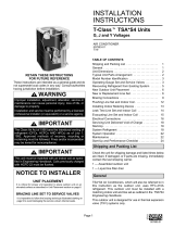
Defrost Control Board
Figure 13
Defrost Interval
Timing Pins
Diagnostic LEDs
24V TerminalStrip
Connections
High Pressure Switch
(optional)
Defrost Thermostat
Low Pressure Switch
Reversing Valve
Compressor Delay Pins
Test Pins
K1 Relay
K2 Relay
FAN
DS1
L
24V
P2
P5
O-OUT
DF
Y1-OUT
HI-PS
U1 U2
DS2
K3 Relay
P6
TST PS DF C R O Y1
C5
S87 LO-PS
C2
P1
30
60
90
TEST
W1
C
L
R
Y1
O
Emergency heat is usually used during an outdoor shut-
down, but it should also be used following a power outage if
power has been off for over an hour and the outdoor
temperature is below 50°F. System should be left in the
emergency heat mode at least 6 hours to allow the crank-
case heater sufficient time to prevent compressor slugging.
Defrost System
The defrost system includes two components: the defrost
thermostat and the defrost control.
Defrost Thermostat
The defrost thermostat is located on the liquid line be-
tween the check/expansion valve and the distributor.
When the defrost thermostat senses 42°F or cooler, the
thermostat contacts close and send a signal to the defrost
control board to start the defrost timing. It also terminates
defrost when the liquid line warms up to 70°F.
Defrost Control
The defrost control board includes the combined functions
of time/temperature defrost control, defrost relay, diagnos-
tic LEDs and terminal strip for field wiring connections
(see Figure 13).

Page 16 # 48306B006
The control provides automatic switching from normal
heating operation to defrost mode and back. During the
compressor cycle (call for defrost), the control accumu-
lates compressor run time at 30, 60, 90 minute field-
adjustable intervals. If the defrost thermostat is closed
when the selected compressor run time interval ends, the
defrost relay is energized and the defrost begins.
Defrost Control Timing Pins
Each timing pin selection provides a different accumulated
compressor run time period during one thermostat run
cycle. This time period must occur before a defrost cycle
is initiated. The defrost interval can be adjusted to 30 (T1),
60 (T2), or 90 (T3) minutes. The defrost timing jumper is
factory installed to provide a 60-minute defrost interval. If
the timing selector jumper is not in place, the control
defaults to a 90-minute defrost interval. The maximum
defrost period is 14 minutes and cannot be adjusted.
A test option is provided for troubleshooting. The test mode
may be started any time the unit is in the heating mode and
the defrost thermostat is closed or jumpered. If the jumper is
in the TEST position at power up, the control will ignore the
test pins. When the jumper is placed across the TEST pins
for 2 seconds, the control will enter the defrost mode. If the
jumper is removed before an additional 5-second period has
elapsed (7 seconds total), the unit will remain in defrost
mode until the defrost thermostat opens or 14 minutes have
passed. If the jumper is not removed until after the additional
5-second period has elapsed, the defrost will terminate and
the test option will not function again until the jumper is
removed and reapplied.
Compressor Delay
The defrost board has a field-selectable function to reduce
occasional sounds that may occur while the unit is cycling
in and out of the defrost mode. The compressor will be
cycled off for 30 seconds going in and out of the defrost
mode when the compressor delay jumper is removed.
NOTE: The 30-second “off” cycle is not functional when
jumpering the TEST pins.
Time Delay
The timed-off delay is 5 minutes long. The delay helps to
protect the compressor from short cycling in case the
power to the unit is interrupted or a pressure switch
opens. The delay is bypassed by placing the timer select
jumper across the TEST pins for 0.5 seconds.
Pressure Switch Circuit
The defrost control includes a low pressure (loss of
charge pressure) switch. A high pressure switch (optional)
can be connected to the board’s HI PS terminals (see
Figure 13 on page 15).
During a single demand cycle, the defrost control will lock
out the unit after the fifth time that the circuit is interrupted
by any pressure switch wired to the control board. In
addition, the diagnostic LEDs will indicate a locked-out
pressure switch after the fifth occurrence of an open pres-
sure switch (see Table 10). The unit will remain locked out
until power to the board is interrupted, then re-established, or
until the jumper is applied to the TEST pins for 0.5 seconds.
NOTE: The defrost control board ignores input from the
low pressure switch terminals as follows:
• During the TEST mode
• During the defrost cycle
• During the 90-second start-up period
• For the first 90 seconds each time the reversing
valve switches heat/cool modes
If the TEST pins are jumpered and the 5-minute delay
is being bypassed, the LO PS terminal signal is not
ignored during the 90-second start-up period.
Diagnostic LEDs
The defrost board uses two LEDs for diagnostics. The
LEDs flash a specific sequence according to the condition
as shown in Table 10.

# 48306B006 Page 17
MAINTENANCE
Before performing maintenance operations on
system, turn the electric power to unit OFF at
disconnect switch(es). Unit may have multiple
power supplies. Electrical shock could cause
personal injury or death.
WARNING
Before the start of each heating and cooling season, the
following service checks should be performed by a
qualified service technician.
• Inspect and clean outdoor and indoor coils. The
outdoor coil may be flushed with a water hose.
NOTE: It may be necessary to flush the outdoor coil
more frequently if it is exposed to substances which
are corrosive or which block airflow across the coil
(such as pet urine, cottonwood seeds, etc...).
• Visually inspect the refrigerant lines and coils for leaks.
• Check wiring for loose connections.
• Check voltage at the indoor and outdoor units (with
units operating).
• Check amperage draw at the outdoor fan motor,
compressor, and indoor blower motor. Values should
be compared with those given on unit nameplate.
• Check, clean (or replace) indoor unit filters.
• Check the refrigerant charge and gauge the system
pressures.
• Check the condensate drain line for free and unob-
structed flow. Clean drain line, if necessary.
• Adjust blower speed for cooling. Measure the pressure
drop over the coil to determine the correct blower CFM.
• Belt drive blowers: Check drive belt for wear and
proper tensions.
If insufficient cooling is reported, the unit should be
gauged and refrigerant charge checked (see Refrigerant
Charging on page 11).
Defrost Control Board
Diagnostic LEDs
edoM DELneerG
)2SD(
DELdeR
)1SD(
rewoPoN
draoBot ffOffO
/noitarepOlamroN
draoBotrewoP hsalFwolSsuoenatlumiS
elcyCtrohS-itnA
tuokcoL hsalFwolSgnitanretlA
erusserPwoL
tluaFhctiwS ffO hsalFwolS
erusserPwoL
tuokcoLhctiwS ffOnO
erusserPhgiH
tluaFhctiwS hsalFwolS ffO
erusserPhgiH
tuokcoLhctiwS nOffO
Table 10

Page 18 # 48306B006
HOMEOWNER INFORMATION
In order to ensure peak performance, your system must be
properly maintained. Clogged filters and blocked airflow
prevent your unit from operating at its most efficient level.
Turn all electric power to unit OFF at discon-
nect switch(es) before performing any mainte-
nance operations on system. Unit may have
multiple power supplies. Electrical shock could
cause personal injury or death.
WARNING
• Ask your dealer to show you where the indoor unit’s
filter is located. It will be either at the indoor unit
(installed internal or external to the cabinet) or behind
a return air grille in the wall or ceiling. Check the filter
monthly and clean or replace it as needed.
• Disposable filters should be replaced with a filter of
the same type and size. If you unsure of the filter you
need for your system, contact your dealer.
• Many indoor units are equipped with reusable foam
filters. These filters can be cleaned with a mild soap
and water solution. Rinse the filter thoroughly and let
dry completely before returning to unit or grille.
The filter and all access panels must be in place
any time the unit is in operation.
• Some systems are equipped with an electronic air
cleaner, designed to remove the majority of airborne
particles from the air passing through the cleaner. If
your system includes an electronic air cleaner, ask
your dealer for maintenance instructions.
• Inspect and clean indoor coil. The indoor evaporator
coil is equipped with a drain pan to collect condensate
formed as the system removes humidity from the
inside air. Have your dealer show you the location of
the drain line and how to check for obstructions. This
also applies to an auxiliary drain, if one is installed.
• Inspect and clean outdoor coil: Make sure no obstruc-
tions restrict airflow to the outdoor unit. Leaves, trash,
or shrubs crowding the unit can cause it to work
harder and use more energy. Keep shrubbery
trimmed away from the unit and periodically check for
debris which collects around the unit.
The outdoor coil may require frequent cleaning,
depending on environmental conditions. Clean the
outdoor coil with a nonpressurized water hose to
remove surface contaminants and debris. It may be
necessary to flush the outdoor coil more frequently if it
is exposed to substances which are corrosive or
which block airflow across the coil (such as pet urine,
cottonwood seeds, etc...).
Heat Pump Operation
Heat pump units have several characteristics you should
be aware of:
• Heat pumps satisfy heating demand by delivering
large amounts of warm air into the living space. This
is quite different from gas-fired, oil-fired, or electric
furnaces which deliver lower volumes of considerably
hotter air to heat the space.
• Do not be alarmed if you notice frost on the outdoor
coil in the winter months. Frost develops on the
outdoor coil during the heating cycle when tempera-
tures are below 45°F. An electronic control activates a
defrost cycle lasting 5 to 15 minutes at preset inter-
vals to clear the outdoor coil of the frost. A shift in
sound type does occur during the defrost mode.
• During the defrost cycle, you may notice steam rising
from the unit. This is a normal occurrence. The
thermostat may engage auxiliary heat during the
defrost cycle to satisfy a heating demand. The unit will
return to normal operation at the conclusion of the
defrost cycle.
In case of extended power outage...
If the outdoor temperature is below 50°F and power to the
outdoor unit has been interrupted for 6 hours or longer,
observe the following when restoring power to the heat
pump system.
• Set the room thermostat selector to the “Emergency
Heat” setting to obtain temporary heat for a minimum
of 6 hours. This will allow system refrigerant pres-
sures and temperatures enough time to return to a
stabilized condition.
• In the Emergency Heat mode, all heating demand is
satisfied by auxiliary heat; heat pump operation is
locked out. After a 6-hour “warmup” period, the
thermostat can then be switched to the “Heat” setting
and normal heat operation may resume.
Thermostat Operation
Though your thermostat may vary somewhat from the
description below, its operation will be similar.
Temperature Setting Levers
Most heat pump thermostats have two temperature
selector levers: one for heating and one for cooling. Set
the levers or dials to the desired temperature setpoints for
both heating and cooling. Avoid frequent temperature

# 48306B006 Page 19
adjustment; turning the unit off and back on before
pressures equalize puts stress on unit compressor.
Fan Switch
In AUTO or INT (intermittent) mode, the blower operates
only when the thermostat calls for heating or cooling. This
mode is generally preferred when humidity control is a
priority. The ON or CONT mode provides continuous indoor
blower operation, regardless of whether the compressor or
auxiliary heat are operating. This mode is required when
constant air circulation or filtering is desired.
System Switch
Set the system switch for heating, cooling, or auto opera-
tion. The auto mode allows the heat pump to automatically
switch from heating mode to cooling mode to maintain
predetermined comfort settings. Many heat pump thermo-
stats are also equipped with an emergency heat mode
which locks out heat pump operation and provides
temporary heat supplied by the auxiliary heat.
Indicating Light
Most heat pump thermostats have an amber light which
indicates when the heat pump is operating in the emer-
gency heat mode.
Temperature Indicator
The temperature indicator displays the actual room
temperature.
Programmable Thermostats
Your system may be controlled by a programmable thermo-
stat. These thermostats provide the added feature of
programmable time-of-day setpoints for both heating and
cooling. Refer to the user’s information manual provided
with your particular thermostat for operation details.
Preservice Check
If your system fails to operate, check the following before
calling for service:
• Check to see that all electrical disconnect switches
are ON.
• Make sure the thermostat temperature selector is
properly set.
• Make sure the thermostat system switch is properly set.
• Replace any blown fuses, or reset circuit breakers.
• Make sure unit access panels are in place.
• Make sure air filter is clean.
• Locate unit model number and have it handy before
calling.

Page 20 # 48306B006
Start-Up and Performance Checklist
Job Name _______________________________ Job No. ________________ Date ______________
Job Location _____________________________ City ___________________ State ______________
Installer _________________________________ City ___________________ State ______________
Unit Model No.______________ Serial No. ___________________
Service Technician ________________________________________ Nameplate Voltage ______________
Rated Load Ampacity ________ Compressor Amperage ____________ Outdoor Fan ______________
Maximum Fuse or Circuit Breaker ________________________
Electrical Connections Tight? Indoor Filter Clean? Supply Voltage (Unit Off) ________________
Indoor Blower RPM _____________ S.P. Drop Over Indoor (Dry) ____________
Outdoor Coil Entering Air Temperature _____________ Voltage with Compressor Operating _____________
Outdoor Fan Checked?
Cooling
Liquid Line Pressure __________ Suction Line Pressure ___________ Refrigerant Charge Checked?
Heating
Liquid Line Pressure __________ Suction Line Pressure ___________ Refrigerant Charge Checked?
Refrigerant Lines: Leak Checked? Properly Insulated?
Service Valves: Fully Opened? Caps Tight?
Thermostat: Calibrated? Properly Set? Level?
Sequence of Operation
Heating Correct? Cooling Correct?
/