Page is loading ...

Safety warning …………………………………………………………………………………………………………………………………2
Product features .………………………………………………………………………………………………………………………………2
1.Technical parameters …………………………………………….…………………………………………………………………………2
2.Models and specifications ..…………………………………………………………………………………………………………………2
3.Diagram and installing size …………………………………………………………………………………………………………………2
4.Wiring diagram ………………………………………………………………………………………………………………………………2
4.1 Connecting sensors …….….……………………………………………………………………………………………………………3
4.1.1 Thermocouple ………………………...………………………………………………………………………………………………3
4.1.2 Dual lines PT100 sensor……….……..………………………………………………………………………………………………3
4.1.3 RTD sensor……….……………………………...……………………………………………………………………………………3
4.2 Power supply connection ……………..…………………………………………………………………………………………………3
4.3 connection for control signal output ……………………………………………………………………………………………………3
4.4 Connection for alarm control ……………………………………………………………………………………………………………3
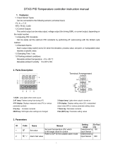
5.Panel instruction ……………..………………………………………………………………………………………………………………3
6.Operation instruction ...………………………………………………………………………………………………………………………3
6.1Display status ……………..………………………………………………………………………………………………………………3
6.2 View output value ………………………………...………………………………………………………………………………………3
6.3 Automatic/Manual control switch ………………………………………………………………………………………………………3
6.4 Value setting ……………...………………………………………………………………………………………………………………3
6.5 Launch self-tuning function ……...………………………………………………………………………………………………………3
6.6 Workflow for setting …………………………………………………………………………………………………………………...…4
6.7 Parameters setting ………………………………………………………………………………………………………………………4
6.8 Parameters related to alarm output: “HiAL,LoAL,dHAL,dHAL,dF,ALP,CF” ……..……………….……………..……………………5
6.8.1 Alarm parameters: HiAL,LoAL,dHAL,dHAL …………………………….……………………………………………………….…5
6.8.2 Defining parameter for alarm ALP ………………………………………………………………………..………………………5
6.8.3 Hysteresis Band dF …………………………………………………………………………………………………………………5
6.8.4 Function parameter CF ……………………………………………………………………………………………………………..5
6.9 Parameters related to input “Sn,diP,diL,diH,DL,Sc” …………………………………………………………………….……………5
6.9.1 Sensor type input “Sn” …………………………………………………………………………………………………………...…5
6.9.2 Decimal point position“diP” …………………………………………………………………………………………………………5
6.9.3 Definition parameters "diH" and "diL" for linear input range …………………………..…………………………………………5
6.9.4 Filtering parameter“dL”………………………………………………………………………………………………………………5
6.9.5 Sensor Calibration“Sc”………………………………………………………………………………………………………………5
6.10 Parameters related to control output“oPI,oPL,oPH,CtrL” …………………………………………………………………...………5
6.10.1 Output mode parameters "oPI", "oPL" and "oPH" are used for limiting output …………………………………………..……5
6.10.2 Adjustment mode parameter "CtrL" ………………………………………………………………………………………………6
6.11 PID control parameters related to self-tuning “M50, P, t” and functional parameter “CtL”……………………………………..6
6.11.1 6.11.1 Holding parameter "M50" …………………………………………………………………………………………………..6
6.11.2 Rate parameter "P" ……………………………………………………………………………………….………………………6
6.11.3 Hysteresis time "t"…………………………………………………………………………………………………………..………6
6.11.4 Function parameter "CtL" ………………………………………………………………………………………………………….6
6.12 Communication parameter “Addr、bAud” ……………………………………………………………………………………………6
6.13 Field parameter "EP1 - EP8" ……………………..……………………………………………………………………………………7
6.14 Permission for parameters “Loc”“LOC” ……………………………………………………………………………………………7
6.15 Common faults and handling methods ……………………………………………………………………………….………………7
7 Wiring instruction ……………………………………………………………………………………………………………………………7
7.1 Directly control load by the internal relay of the instrument ..…………………………………………………………………………7
7.2 Control the load via external contactor …………………………………………………………………………………………...……7
7.3 SSR control ……………………………….……………………………………………………………………………………………7
7.4 Solenoid valve or relay control ………..………………………………………………………………………………………………8
7.5 Control load via external contactor (24V) …………………………………………………………………………………………..…8
8.Field application example …………………………………………………………………………………………………………………..8
User Manual
ITC-100 PID Temperature Controller
V1.0 2015-6-30
Contents
1
© 2015 Inkbird Inc. All rights reserved.
www.ink-bird.com, [email protected]

Table 1: Product models and specifications
●Never disassemble, refit and repair this product, or touch the inner components
by yourself, otherwise, there will be risk of electric shock, spark or malfunction.
●If the replay was serving beyond its estimated lifetime, there will be risk of
contact fusion and burning. It’s a must to always pay attention to the using
environment of relay, and using the relay within its rated load and estimated
lifetime. The estimated lifetime of the relay varies according to the output
●Panel size: DIN(48×48mm)
●Compatible with various temperature sensors (K, S, Wre, T, E,
J, B, N, CU50, PT100)
●Wide control temperature range: -50 - 1300ºC ( type K thermocouple)
●Display and control accuracy: 0.1 ºC,
high measuring precision: ±0.2%FS
●PID control mode with high-performance self-tuning function
●User-defined output and alarm modes
●Adjustable digital filtering for reducing external interference
●Self-calibration available for ensuring long term stability of the instrument
●high luminance LED screen with height 0.39“ characters,
anti-dazzle panel, well visibility
● Inbuilt switching power supply applicable for wide voltage range with
low power consumption
3.1 Insert temperature controller into the mounting hole in the panel, then put
on the fixer from the rear and hold it temporarily, make sure there is no gap
among temperature controller, panel and fixer. After that, fix the temperature
controller with attached two bolts of the fixer under torque of 0.29N to 0.39N.
3.2 Make sure the surrounding temperature is within the stipulated
temperature range, especially when there are two or more temperature
controllers.
AC/DC 12-24V
3.Diagram and installing size (unit: mm)
Figure 3: Panel Cutout
ITC-100VH
SSR control output
AC 100-240V
ITC-100RH
Relay control output
AC 100-240V
ITC-100RL
Relay control output
Storing temperature
2.Models and specifications
Model
Control output
Voltage
Figure 2: Mounting Bracket
Figure 1: Shell Size
ITC-100VL
SSR control output
AC/DC 12-24V
Weight
About 140g
Relay output: AC 250V 3A (resistive load)
Alarm output
Figure 4:Wiring diagram
Working temperature
Working humidity
-25 - 65ºC (No ice or moisture condensation)
■Safety warning
About 3W (12V - 24VDC)
85 to 100% of the rated voltage
About 5VA (100V - 240VAC)
About 4VA (12V - 24VAC)
●It’s a must to use this product within its specification and using scope.
load and switching condition.
●When power on, do not connect, disassemble and touch terminals, as those
may cause damage due to spark, malfunction or electric shock.
●No metal fragment, wire thread or metal dusts produced during installation
are allowed to be inside the device, otherwise, there will be risk of electric
●Please do not use this product in flammable and explosive locations,
■ Product features
Voltage output (for driving SSR): 12VDC, 30mA DC
Maximum load: 600Ω
Power
Working voltage
±0.2%FS 0.1ºC(<1000ºC); 1ºC(≥1000ºC)
0.5 seconds
0-50ºC
Relay output: AC 250V 3A (resistive load)
Control output
Relay output: AC 250V 3A (resistive load)
AC 100-240V 50/60Hz
AC/DC 12-24V 50/60Hz
DC 12-24V
PV: high luminance LED screen with 4 digits of height
9.9mm displayed in red
SV: high luminance LED screen with 4 digits of height
8.0mm displayed in green
Sampling period
Display accuracy
Characters
Temperature
compensation
Electrical endurance of relay: 100,000 times
Rated Voltage
shock, fire or malfunction.
otherwise, there will be risk of damage caused by explosion.
1.Technical parameters
RH 35-85%
-10 - 55ºC (No ice or moisture condensation)
4.Wiring diagram
2
© 2015 Inkbird Inc. All rights reserved.
www.ink-bird.com, [email protected]

Please refer to the input sensor reference table to select sensor type and set
the code. The default setting of sensor type is type K thermocouple. If other type 6.1 Display status
sensor was adopted, it’s a must to reset the configuration. After power on, the instrument will conduct self-tuning, then enter measuring
If error occurred when some thermocouples are used in different environments, and monitoring status automatically. PV window displays current measured
press SC to calibrate as per the detailed stipulation in this manual. value, while SV window displays setting value; If “orAL” was displayed
alternately between PV and SV windows, it means input value exceeded
measuring range (or sensors in open loop), or input setting is incorrect.
#3 and #4 terminals are for connecting thermocouple. No inverse connection of When there was alarm output, SV window will alternately display characters
positive pole and negative pole are allowed. For common thermocouples, positive
related to the alarms:
pole is red, while negative pole is blue or green. If the poles were connected HiAL(alarm for high limit),LoAL(Alarm for low limit),
inversely, the measured value will be displayed inversely on the screen. dHAL(alarm for plus deviation),dLAL(alarm for minus deviation).
6.2 View output value
#3 and #4 terminals are the input ports for dual lines PT100 sensor, at the same Press “SET” key (no longer than 1 second), if SV window displays character
time #4 and #5 terminals should be connected together. “A”(for instance), it indicates automatic control mode, while if the displayed
character is “M” (for instance: ), it indicates the manual control mode.
When connecting three lines RTD sensor, #3 terminal is for red wire, #4 and #5
are for other two blue lines. For some sensors, #4 and #5 terminals should be
6.3 Automatic/Manual control switch
connected together. Press “«” key (no longer than 1 second), the temperature controller can
switch between automatic and manual control mode without interference to
#9 and #10 terminals are for connecting power supply, polarity is indifferent when the operation. Under automatic control mode, RUN indicating light will off;
connecting. Before installation, it’s a must to confirm the compliance of the input and under manual control mode, RUN indicating light will on.
voltage to product specification, otherwise, there will be risks of abnormal usage, (remarks: if the running status of the function setting is “2: forbid manual
electric shock and fire. mode”, above operation is invalid).
4.3.1 The output driving voltage and current of Model ITC-100V are 12VDC and
30mA respectively, while #6 output terminal is for negative pole, and #8 terminal 6.4 Value setting
is for positive pole. It can drive SSR (Solid-state replay). Please note that the
When SV window displays setting value, press “︽” key (“︾” key) to increase
positive pole and negative pole shouldn’t be connected inversely. (decrease) setting value. Press “«” key to move cursor to required numerical
4.3.2 Model ITC-100R output relay control signals. COM7 is public port,
position. Keeping “︽” key or “︾” key to be pressed could increase or
COM6(NC) is normally closed, COM8 (NO) is normally opened. It could directly decrease the value quickly.
control load of AC250V, <3A; for controlling load of AC250V, >3A, external high
capacity controller is needed. 6.5 Launch self-tuning function
When use the instrument for the first time, it’s a must to use the self-tuning
Alarm is controlled by relay signals. COM12 (COM) is public port, COM1 is function of the instrument to determine control parameters (M50, P and t)
normally closed, COM11 is normally opened, maximum load is AC250/3A for an ideal control effect. Press “«” key for over 2 seconds, then the SV
(resistive load). window will display characters “A” and “T” alternately, and the system will
enter self-tuning mode. When self-tuning, the temperature controller will
conduct digital adjustment. After oscillation for 2 to 5 times, the instrument
will automatically set the PID control parameters (parameters M50, P and T).
PV window displays
After self-tuning, the system will return to PID automatic control mode.
measured value or set functional symbols During self-tuning, press “«” key for over 2 seconds to cancel self-tuning,
SV window displays then the characters “AT” displayed in SV window will disappear.
setting value or set value to be read Attentions: for temperature controller which had run self-tuning before,
Working indicating light
it’s a must to set parameter CtrL as “2” before launching another self-tuning
OUT: Indicating control signal output (please refer to section “parameters setting and definition” in this manual
AL1: Indicating AL1 alarm for detailed operation). The control parameter value will vary according to
AL2: Indicating AL2 alarm setting temperature, therefore, it’s a must to run self-tuning with the most
RUN: Manual indication frequently used setting value of the system. If the setting value often
“INCREASE” key: when setting value, press“︽” key to increase changes, run self-tuning with the middle value of setting values.
value, keeping this key to be pressed can increase value quickly.
“DECREASE”key: when setting value, press “︾” key to decrease
value, keeping this key to be pressed can decrease value quickly.
“MOVE“ key: when setting temperature value or parameters,
use this key to move cursor to required numerical position.
“SELF-TUNING” key: when in normal display mode, long
press this key for over 2 seconds to start or stop self-tuning.
“SWITCHING” key: when in normal display mode, press this
key for less than 1 second to switch automatic and manual mode.
“SET” key: when in normal display mode, press this key to view setting value for control
signal output; long press for over 2 seconds to enter parameters setting mode.
6. Operation instruction
4.4 Connection for alarm control
Figure 5
4.1 Connecting sensors
4.1.2 Dual lines PT100 sensor
5. Panel instruction
4.3 Connection for control signal output
4.2 Power supply connection
4.1.3 RTD sensor
4.1.1 Thermocouple
3
© 2015 Inkbird Inc. All rights reserved.
www.ink-bird.com, [email protected]

6.7 Parameters setting 6.6 Workflow for setting
Table 2: parameters setting and definition After instrument powered on and run self-inspection, press “SET” key for
over 2 seconds to enter parameters setting mode. User can press “︽”
key(or “︾” key) to set the value. After value set, press “SET” key to
confirm and go for setting for another function. Then repeat above
operation, till all the functions are configured OK.Quit setting mode,
and enter PV/SV monitoring mode.
Attentions: if parameters were changed during parameters setting mode,
the temperature controller will save the change if there is no further
operation for over 10 seconds, and return to PV/SV monitoring mode.
dLAL:Deviation high
alarm
dF:Return difference
SC:Revise displayed
value
oP1: Output mode
Opl:Low limit of output
Oph:High limit of output
CtrL:Control mode
ALP:Alarm definition
CF:System functions
selection
HIAL:Alarm value for
high limit
LOAL:Alarm value for
low limit
dHAL:Deviation high
alarm
diH:Displayed value for
low limit
Parameter
Definition
HIAL
Upper alarm limit
LoAL
Lower alarm limit
0
dHAL
Deviation high alarm
dLAL
Deviation low alarm
dF
Hysteresis band
1
9999
500
Control mode
CtrL
none
0
2
1
9600
See 6.8.1
0~9999
1℃
3
See 6.10.2
0: On/OFF
See 6.8.3
0.3
120
0
0~31
2:Heater
0~220
0
-199~+999
1℃
2: Sel-turning
-9999
40
0~3
1~120
1~9999
1:0-10mA
4
0/2:time proportioning
-1999~+9999
1: automatic
2: No manual
0~220
0~20
3:Cooler
0~9999
-1999~+9999
0~42
0~999
M50
Integral Time
P
Differential
t
0: manual
Hysteresis time
Ctl
Control period
Sn
Input sensor
diP
decimal point position
diL
Displayed value for low
limit
diH
Displayed value for high
limit
SC
Sensor Calibration
LOC
Baud
dl
Opl
Low limit of output
Oph
High limit of output
ALP
Alarm definition
Digital filtering
Addr
See 6.10.1
Communication address
Communication baud
rate
1%
0~63
0~4800
100
See 6.8.4
See 6.9.5
See 6.10.1
See 6.10.1
See 6.8.2
1%
0
0
2
second
0.01S/℃
1 Digital
See 6.13
1 Digital
See 6.9.4
EP1 ~EP8
8 definitions for field
parameter
See 6.11.4
See 6.9.1
See 6.9.2
See 6.9.3
See 6.9.3
Select Any
Parameters from it
See 6.12.1
See 6.12.2
second
1000
0
Output mode
oP1
System functions
selection
CF
Automatic/Manual
status
run
Permission of revising
parameter
diP:decimal place
diL:Displayed value for
low limit
See 6.11.3
See 6.14
See 6.11.2
See 6.11.3
Value range
Unit
0~9999
See 6.8.1
-1999~+9999
9999
See 6.8.1
0~9999
0~200.0
1℃
0.1℃
1000
-1999~+9999
Remarks
See 6.8.1
Default
9999
1℃
Addr:Communication
address
1,3: PID
0.1℃
Figure 6:Workflow for setting
t:Hysteresis time
Ctl:Control period
Sn:Input sensor
M50:Integral Time
P:Rate
Baud:Communication
baud rate
dl:Digital filtering
run:Running status
LOC:Permission of
revising parameter
EP1-EP8:8 definitions
for field parameter
Press 3S
to enter Setting
Mode
SET
SET
SET
SET
SET
SET
SET
SET
SET
SET
SET
SET
SET
SET
SET
SET
SET
SET
SET
SET
SET
SET
SET
SET
SET
SET
4
© 2015 Inkbird Inc. All rights reserved.
www.ink-bird.com, [email protected]

6.8 Parameters related to alarm output: “HiAL, LoAL, dHAL, dLAL、6.9 Parameters related to input “ Sn, diP, diL, diH, DL, Sc”
dF, ALP, CF” 6.9.1 Sensor type input “Sn”
6.8.1 Alarm parameters: "HiAL、LoAL、dHAL、dLAL". These parameters
Table 4: sensor input code and measuring range
are for setting the alarm function of the instrument. When there is alarm
condition, the system will output alarm signals to drive alarm relay to act
(normally opened contact close/normally closed contact open), and
alternately display the alarm reasons in the bottom screen. The alarm will
be dismissed once the fault is fixed. Alarm conditions are as following:
HiAL: alarm when measured value is larger than HiAL (PV>HiAL).
LoAL: alarm when measured value is smaller than LoAL (PV<LoAL).
dHAL: alarm when plus deviation is larger than dHAL (PV>SV+dHAL).
dLAL: alarm when minus deviation is smaller than dLAL (PV<SV-dLAL).
Generally, user don’t need 4 alarms in effect at the same time. For any
alarm not required, set it to the maximum value to avoid triggering it. For
example, set HiAL=9999, LoAL=-1999, dHAL=9999, or dLAL=9999.
6.9.2 Decimal point position “diP”
6.8.2 Defining parameter for alarm"ALP" Decimal position “diP” is for selecting displaying accuracy. This setting is only
Table 3: defining alarm function
for display. The internal measuring accuracy is fixed to be 0.1℃.
When diP=0, it means the temperature display accuracy is 1℃.
When diP=1, 2 or 3, it means the temperature display accuracy is 0.1℃.
When the temperature display accuracy is set to be 0.1℃, while the measured
temperature is lower than 1,000℃, the temperature will be displayed with
accuracy 0.1℃; when the measured temperature is higher than 1,000℃, the
temperature will be displayed with accuracy 1℃.
Changing diP parameter can only influence the display, there is no influence to
the measuring accuracy.
6.9.3 Definition parameters "diH" and "diL" for linear input range
Above are part of common ALP setting. The setting range is 0 - 31. Linear input includes signals such as current: 0-20mV, 0-60mV;
It defines the output position of 4 alarms -- HiAL、LoAL、dHAL、 voltage: 0-1V, 0-5V; resistance: 0-80Ω, 0-400Ω. The displaying value
dHAL. It’s defined by following formula: range for the signals is -1999 - 9999 (decimal position could be set by
ALP=A×1+B×2+C×4+D×8+E×16 diP). Parameters diH and diL are used to define the display range of
When A=0, HiAL alarm is output by AL1; linear input.
When A=2, HiAL alarm is output by AL2;
When B=0, LoAL alarm is output by AL1;
6.9.4 Filtering parameter “dL”
When B=2, LoAL alarm is output by AL2; ITC-100 has in-built digital filtering system. When the displayed value is
When C=0, dHAL alarm is output by AL1; not stable due to input interference, use digital filtering to smooth it.
When C=1, dHAL alarm is output by AL2; dL=0-20, the larger the dL value, the measured value will be more stable,
When D=0, dHAL alarm is output by AL1; but respond will be more dull. When the instrument is interfered at field,
When D=1, dHAL alarm is output by AL2; gradually increase the dL value till the instant variation of measured value
When E=0, SV screen will display alternately the alarm symbols, is within 2-5 unit. When verifying the instrument, it’s a must to set dL as 0
enabling user to know the reasons for alarm quickly; to improve responding speed.
When E=1, SV screen won’t display alternately the alarm symbols
(except orAL) 6.9.5 Amendment parameter “Sc”
Alarm for input exceed measurable range (orAL) could occur when
Parameter “Sc” is for offset amendment for input to compensate the
there are improper sensor specification setting, input disconnected or deviation of sensor or input signal. For thermocouples, if there is deviation
short circuit. If such alarm occurred, the instrument will stop control, at the cold compensation, use parameter “Sc” to amend.
and keep the output value as stipulated by parameter oPL. No setting
For example, assume input signal is constant (500℃), and Sc value is
is needed for orAL.
0.0℃, then the measured temperature is 500.0℃; while Sc value is 10.0℃,
the measured temperature is 510.0℃. The default value of Sc is 0.
6.8.3 Hysteresis Band (Dead Band) parameter "dF" This parameter shouldn’t be amended unless there is need to calibrate
For avoiding alarm signals caused by input value fluctuation, and the measurement.
consequently malfunction, the instrument has return difference
parameter dF (also called as non-sensitive zone, dead zone, or
6.10 Parameters related to control output “oPI、oPL、oPH、CtrL”
hysteresis). For example, the influence of dF parameter: assume
6.10.1 Output mode parameters "oPI", "oPL" and "oPH" are used for
HiAL value is 800 ℃, dF value is 2.0℃, then only when the measured limiting output
temperature is larger than 802℃(HiAL+dF), the instrument enters HiAL oPI is the mode of main output signal; oPL and oPH are the output low
alarm status. And only when the measured temperature is lesser than limit and high limit respectively.
798℃(HiAL-dF), the alarm will be dismissed.
When oPI=0, main output mode is time proportioning output (professional
6.8.4 Function parameter "CF" PID adjustment) or digital adjustment. Models with SSR, relay, and zero-crossing
Parameter CF is for selecting some system functions: when CF=2, triggering silicon should set oPI=0.
it’s heating control; when CF=3, it’s refrigeration control. When oPI=1, output mode is continuous output (for models with linear
Lower alarm limit
0
Cu50
Pt100
0~1000ºC
0~1000ºC
0~1800ºC
0~1300ºC
J
T
7
20
B
N
E
Input
21
WRe
Code
0
Sensor type
thermocouple
Copper resistor
6
4
5
K
S
Alarm output
Alarm type
ALP
Upper alarm limit
0
Platinum resistor
Deviation low alarm
8
AL2
Deviation high alarm
0
Deviation low alarm
0
Upper alarm limit
1
Lower alarm limit
Deviation high alarm
4
2
AL1
1
2
3
Measuring range
-50~1300ºC
-50~1700ºC
-0~2300ºC
-2000~350ºC
-50~150ºC
-200~600ºC
5
© 2015 Inkbird Inc. All rights reserved.
www.ink-bird.com, [email protected]

current output). Output current are 0-10mA and 2-40mA.
stable stage is 700℃, while when the output is 0%, the temperature of
When oPI=2, output mode is time proportioning output, and AL1 act as
electric furnace is room temperature 25℃, then M50 (optimal value) is
output synchronizing with main output. Under this mode, the AL1 of the
700-25=675℃.
instrument can’t be used to output alarm signals as it’s used as output. M50 is mainly for adjusting the integral action of adjusting algorithm. The
Only AL2 is available for alarm signals (refer to 6.8).
smaller the M50, the strong the integral action. The larger the M50, the
oPL and oPH are the output low limit and high limit. Attentions: the setting weak the integral action (integral time will increase). But when M50=0,
of oPI should be in accordance with the module of main output. system will cancel integral action.
When oPI=1 (current output), oPL and oPH are as following:
0-10mA output: oPL=0, oPH=100 6.11.2 Rate parameter "P"
4-20mA output: oPL=40, oPH=200 P is inversely proportional to the measurement variation when the output is
Example for nonstandard output current: 2-8mA output: oPL=20, oPH=80.
100%. It’s definition is as following.
oPI=0,2 (time proportioning output). Time proportioning output controls
P= 100÷increased measuring value per second, the unit is ℃ or 10
the ratio of open and close of relay (or ratio of high and low voltage defined units (when linear input). For example, when the output is 100%,
output of SSR) in a fixed period to realize output variation. Time no heat dissipation, and the temperature of the electric furnace increases
proportioning output could be regarded as a square wave, its period
1℃ per second, then:
is equal to control period Ctl. Output value is proportional to the duty P=100÷1=100
ratio of square wave, varying from 0% to 100%. Users can use oPL P has influence to adjusting proportion and differential. When the P value
and oPH to limit the output range of time proportioning output. For increased, the adjusting proportion and differential action will increase
example, to limit the output within range 20%-60%, set oPL=20, proportionally; while when the P value decreased, the adjusting proportion
oPH=60. Generally, the default setting of time proportioning output is and differential action will decrease proportionally. P has no influence to
oPL=0, oPH=100, that is, no output limitation. integral action. Set P=0 is equal to set P=0.5.
(wave when output is 40% and 60%) 6.11.3 Hysteresis time "t"
For industrial control, the hysteresis effect of object system is the main factor
which influences control effect. The larger the system hysteresis time, more
difficult to achieve ideal control effect. Hysteresis time t is a new important
parameter introduced into professional PID algorithm in comparing with PID
algorithm. The instrument can conduct fuzzy logic operation according to
parameter t to perfectly solve overshoot and oscillation, as well as achieve
fastest respond speed. t is defined as the time needed for the electric furnace
reaching 63.5% of its maximum heating rate when heating with a fixed power.
6.10.2 Adjustment mode parameter "CtrL"
ITC-100 allows digital adjustment or professional PID adjustment. 6.11.4 Function parameter "CtL"
Select it by CtrL parameter. CtL value can be set between 0.5-120 seconds (CtL value 0 is equal to 0.5
When CtrL=0, adopt digital adjustment (ON-OFF). It’s only for
seconds). It reflects the operation speed of instrument control. For time
applications where the requirements are not strict. proportioning output (triggering by SSR voltage/relay/control silicon), it
When CtrL=1, adopt professional PID adjustment. It’s an improvement represents the control period of the instrument; for linear current output,
based on PID adjustment and fuzzy adjustment, suitable for various it controls the output fluctuation (time constant for digital filter to output value).
objects, and well control on fast changing objects and hysteresis. It’s If CtL is far lesser than hysteresis time t (lesser than 1/5 - 1/10), there is no
the default setting when product leaving factory. Under this setting, difference if changing CtL. For example, when hysteresis time t is 100
self-tuning could be launched by panel operation. seconds, then the control effect will be same no matter CtL=0.5 seconds
When CtrL=2, launch self-tuning. It’s same operation as launching or CtL=10 seconds.
self-tuning by panel operation. If another self-tuning is needed after
Principle for determining CtL:
self-tuning, set CtrL as 2 to re-launch self-tuning. a. When under time proportioning output, and using SSR or controlled silicon
When CtrL=3, adopt professional PID adjustment. After self-tuning, as output actuator, the control period could be short (generally 4 seconds) to
the instrument will apply such setting. Under this setting, no self-tuning improve control accuracy. When using relay open and close to control output,
is allowed from panel operation, thus to avoid maloperation to launch short control period will be harm to the lifetime of mechanical switch, so the
self-tuning. control period is generally 20 seconds.
b. When the output is linear current, small CtL value can speed up the respond
6.11 PID control parameters related to self-tuning “M50, P, t” and against intelligent adjustment, and improve control accuracy. But the large
functional parameter “CtL” differential action may cause frequent change of output current. If the actuator
PID control parameters M50, P and t are the control parameters for is regulating valve, and there are frequent valve actions, enlarge CtL properly
professional PID adjusting algorithm. M50, P, and t are determined by to slow down the valve action till it meet the requirement.
self-tuning. This instrument adopted the latest professional PID
adjustment which is a new algorithm enhanced with fuzzy logic. 6.12 communication parameter “Addr, bAud”
Following are the definition of each parameter.
6.12.1 Parameter Addr defines the communication address of the instrument,
its effective range is 0 - 63. Instruments in a same communication line should
6.11.1 Holding parameter "M50"
be set with different Addr to distinguish from each other.
M50 defines the deviation for measured value when the object is stable, 6.12.2 Parameter bAud defines the communication baud rate, its effective
and the output value is 50% (when oPI=1, the current is 5.0mA). For range is 300 - 4800 bit/s
example, for finding the best M50 value of a electric furnace, assume
the output is keeping at 50%, the temperature of the electric furnace in
Figure 7 diagram of time proportioning output
6
© 2015 Inkbird Inc. All rights reserved.
www.ink-bird.com, [email protected]

6.13 Field parameter "EP1 - EP8"
7. Wiring instruction
After setting the instrument, most parameters don’t need to be amended 7.1 Directly control load by the internal relay of the instrument.
at field. Besides, operators generally don’t understand many parameters,
and there is risk of fault caused by wrong setting by operators.
Generally, intelligent instrument has parameter lock (Loc) function. Common
parameter lock will lock all the parameters. Sometimes, certain parameters
need to be amended or adjusted at field by the operators. For example,
parameters such as alarm high limit or alarm low limit. In parameter table,
EP1 - EP 8 are 8 field parameters for operators. The value of parameter
EP is other parameters, such as HiAL and LoAL. When Loc=0 or 1,
selected parameters will be displayed, other parameters won’t be displayed
and amended. This function can speed up the amendment, and avoid
important parameters (such as input and output parameters) been
amended incorrectly. Control the heater by the internal relay of the instrument, no external control
There are maximum 8 field parameters available for parameter EP1- EP2. circuit is needed. This mode is only applicable for heater whose maximum
If field parameters are less than 8 (sometime none), they should be defined load is 250V/3A or 120V/6A.
orderly from EP1 to EP8. Vacant field parameters are defined as nonE. The internal control of alarm is relay output control which controls the power
supply of the speaker. User can use bulb to replace with the speaker as alarm.
6.14 Permission for parameters “Loc”
Protection function Loc: when Loc is set as value except 2, 40, 808, the 7.2 Control the load via external contactor
instrument only display the filed parameters (EP1 - EP8) and Loc. Only if
set Loc as 2, 40 or 808, all the parameters can be amended.
When Loc=0, field parameters (EP1 - EP8)and temperature setting
value can be amended.
When Loc=1, field parameters can’t be amended (except Loc).
When Loc=2, 40 or 808, all the parameters and temperature setting
value can be amended.
6.15 Common faults and handling methods
Table 5:Error and handling
Instrument control output via external relay or contactor. With this method,
the user can select external relay or contactor based on the power of heater,
avoid output limitation of the internal relay of the instrument, and improve the
lifetime of the instrument.
7.3 SSR control
ITC-100VH’s output control signal is DC12V voltage for controlling external
SSR to control the heater. User can select SSR based on the power of the
heater. SSR is a kind of electronic switch without contactor, which can be
used for higher frequency control than relay, featuring more stable temperature
control for heater and long lifetime.
orAL displayed
on the
instrument
Sensor fault
Check whether sensor is connected
correctly
Malfunction of
relay
Wrong setting
for control
output
Figure 8:ITC-100RH Wiring diagram
Figure 10:ITC-100VH Wiring diagram
Faults
Figure 9:ITC-100RH Wiring diagram
Power cable is
not well
connected
Check whether the power cable is
bad or wrongly connected
Instrument fault
Contact manufacturer or dealer
Wrong
measured value
Wrong
graduation
mark selected
Select correct graduation mark in
accordance with input signal
Wrong
connection for
sensors
Connect signal cable correctly
Reasons
Handling methods
PV and SV
screen not work
Wrong input
voltage
Check whether the input voltage is in
accordance with the specification of
the instrument
Refer to the alarm instruction in the
user manual to selected required
alarm mode
No control
output
Wrong wiring
for control
output
Connect control output cable
correctly
Wrong
graduation
mark selected
Select correct graduation mark in
accordance with input signal
Wrong
connection for
sensors
Connect signal cable correctly
7
© 2015 Inkbird Inc. All rights reserved.
www.ink-bird.com, [email protected]

7.4 Solenoid valve or relay control 8. Field application example
For example, the application of instrument for oven. Following example is based
on ITC-100RH and ITC-100VH, the required temperature is 150 ºC, and the high
limit is 160ºC.
ITC-100RL is generally used for low voltage devices. It’s a must to pay
attention to whether the power supply voltage and alarm voltage is within
Figure 13:ITC-100RH Wiring diagram
the stipulated range when wiring.
7.5 Control load via external contactor (24V)
Figure 14:ITC-100VH Wiring diagram
Wiring steps:
1. Connect sensor: the sensor in figure 13 and 14 are both three lines RTD
sensors. Their connection method are the same. Red wire is for COM3,
other two blue wires are for COM4 and COM5 (two blue wires can exchange
COM port with each other).
2. Connect alarm: ITC-100RH and ITC-100VH’s alarm control output are the
ITC-100RL’s control mode is the same as figure 9. Please note that the same. COM12 is the power input port for alarm, which should connect with
power supply for heater is high voltage(120VAC), the power supply for phase line (L). COM11 is alarm control output port, which should connect
instrument is 24VAC (low voltage). with alarm. The other line of the alarm should connect with the null line.
3. Connect heating tube: ITC-100RH controls heating tube by its internal relay.
COM7 of the instrument connect with the power input port, which should
connect with phase line (L). COM8 is the control output port, which should
connect directly with the heating tube. The other wire of the heating tube
should connect with null line (N); TC-100VH output DC12V voltage as control
signal, driving SSR to control heating tube. COM8 of the instrument output
positive voltage, which should connect with SSR’s positive pole; COM6 of the
instrument output negative voltage, which should connect with SSR’s
negative pole. The polarity should not be inversely connected.
4. Connect power supply: the power supply port of the instrument are COM9
and COM10, which are for the phase line and null line respectively. A dual
linked switch should be connected in front of power supply, and connect
fuse in phase line(L). The wire used must be able to bear the load current,
otherwise, there will be risk of accidents such as fire
For simple users, no need to master all instructions, as long as the parameters
of the following parameters in the process to set up to get the ideal control effect,
set up flow chart as below:
Figure 11:ITC-100RL Wiring diagram
Figure 12:ITC-100RL Wiring diagram
8
© 2015 Inkbird Inc. All rights reserved.
www.ink-bird.com, [email protected]

Setting target temperature SV=150
Keep the Default value
Sn=20 (CU=20, more detail please check
6.9.1)
Setting Alarm value for
high limit
Setting Control mode
Setting Input sensor
value
Initial display
︽
Keep the Default value
Keep the Default value
Keep the Default value.
2:Heater, 3:Cooler
Setting Revise
displayed value
Setting Alarm
definition
Setting System
functions selection
Setting HIRL=160, more setting of alarms,
please check 6.8.1
*if don't need to set this parameter, press
SET key to run into next setting.
Keep the Default value
Keep the Default value
Setting Permission of
revising parameter
8 definitions for field
parameter
Figure 15:Workflow of sample
Power On
SET
SET
SET
SET
SET
SET
SET
SET
SET
9
© 2015 Inkbird Inc. All rights reserved.
www.ink-bird.com, [email protected]
/