Honeywell Q539A Installation Instructions Manual

Type
Installation Instructions Manual

This manual is also suitable for

Honeywell Q539A: A Versatile Subbase for Efficient Climate Control

The Honeywell Q539A subbase provides precise temperature management and flexible system control for heating and cooling systems. With its intuitive interface and a range of features, it's an ideal choice for maintaining comfort and energy efficiency in your home. Here's a quick overview of its capabilities:

  • Heating and Cooling System Switching: The Q539A allows you to effortlessly switch between heating and cooling modes, ensuring year-round comfort.

  • Adjustable Fan Control: Choose between automatic fan operation, which adjusts based on system demand, or continuous fan operation for consistent airflow.

® U.S. Registered Trademark
Copyright © 2002 Honeywell • •All Rights Reserved
INSTALLATION INSTRUCTIONS
69- 0579- 4
T87F Zone Thermostat and
137421N,P Wallplates; T87F Zone
Thermostat and Q539A,B Subbases
APPLICATION
The T87F Thermostat provides 24 Vac single-stage
temperature control of Honeywell Zone Control Panels.
The panel operates the heating or cooling systems and
zone dampers in response to the T87F Zone
Thermostats. The T87F is used with the 137421N or P
Wallplate (provided) or Q539A or B Subbase (ordered
separately), depending on application. See Table 1 for
thermostat/wallplate and subbase applications and
specifications.
MERCURY NOTICE
If this control is replacing a control that contains
mercury in a sealed tube, do not place your old
control in the trash. Dispose of properly.
Contact your local waste management authority
for instructions regarding recycling and the
proper disposal of an old control.
INSTALLATION
When Installing This Product...
1. Read these instructions carefully. Failure to follow
them could damage the product or cause a hazard-
ous condition.
2. Disconnect the power supply to prevent electrical
shock or equipment damage.
3. Check the rating given in the instructions and on
the product to make sure the product is suitable for
your application.
4. Installer must be a trained, experienced service
technician.
5. After completing installation, use these instructions
to check out the product operation.
Table 1. Thermostat/Wallplate and Subbase Applications and Specifications.
Thermostat
/Wallplate
or Subbase Application
Switching
CommentsSystem Fan
T87F3707/
137421N
T87F3715/
137421P
To control zones other than zone
1 using MM-2 or MM-3 Zone
Control Panels. To control zone
damper actuators in independent
heating-only systems.
None None Wallplate included with
thermostat. Terminals are
marked: W, R, Y.
T87F3715/
Q539A1436
T87F3707/
Q539A1428
To control any zone on TZ-3,
EZ-2, EZ-4, EMM-3 or EMM-3U
or zone one on MM-2 or MM-3
Zone Control Panels.
COOL-OFF-
HEAT
ON-AUTO Q539A ordered
separately. Terminals
marked: R,W,Y,G,O,B.
T87F3715/
Q539B1039
T87F3707/
Q539B1021
To control zone damper
actuators in independent zones
in heating-cooling systems.
HEAT__COOL None Q539B ordered
separately. Terminals
marked: 4,5,6.
T87F ZONE THERMOSTAT AND 137421N,P WALLPLATES; T87F ZONE THERMOSTAT AND Q539A,B SUBBASES
69-0579-4 2
Selecting Location
Install the thermostat about 5 ft (1.5 meters) above the
floor in an area with good air circulation at average
temperature.
Do not install the thermostat where it can be affected
by:
drafts or dead spots behind doors and in corners.
hot or cold air from ducts.
radiant heat from sun or appliances.
concealed pipes and chimneys.
unheated (uncooled) areas such as an outside
wall behind the thermostat.
Handle this thermostat carefully; it is a precision
instrument that was carefully calibrated at the factory.
CAUTION
Electrical Shock Hazard
Can cause personal injury or equipment
damage.
Disconnect power supply before installation.
Mounting and Wiring
IMPORTANT
To prevent interference with thermostat linkage,
keep wire length to a minimum and run wires as
close as possible to the subbase.
All wiring must comply with local codes and ordinances.
T87F Zone Thermostat and wallplate or subbase are
used in zoned conventional single-stage heating or
heating-cooling systems.
137421 Wallplate or Q539 Subbase
REPLACEMENT APPLICATION
1. Remove old equipment. Dispose of properly. See
Mercury Notice.
2. Check the existing wallplate or subbase wires for
cracked or frayed insulation.
3. Replace any wires in poor condition.
4. If the wires are plastered into the wall, make a hole
next to the wires so they can be pushed back into
the wall later.
5. Continue with step 3 for New Installation.
NEW INSTALLATIONS
1. Run low voltage thermostat cable (if necessary) to
the thermostat location.
2. Pull about 3 in. (76 mm) of cable through a hole in
the wall.
3. Connect wires to the terminals inside the wallplate
or subbase. See Fig. 1 and 2 or zone control panel
installation instructions for wiring diagrams of typi-
cal zone systems.
4. Push excess wire back through the hole and plug
any opening with insulation to prevent drafts that
can affect thermostat performance.
5. Loosely fasten the thermostat wallplate or subbase
to the wall with a screw through the left mounting
hole. See Fig. 3.
6. Adjust the wallplate or subbase so it is approxi-
mately level and start the second screw through
the right mounting slot. Do not tighten.
Fig. 1. Wiring single ARD (power open) to thermostat.
Fig. 2. Wiring T87F Thermostat and Q539B Subbase
or 137421 Wallplate in independent zone.
137421 Wiring Cross Reference
Old Terminal New Terminal
4W
5R
6Y
J
HEAT COOL HEAT COOL
Y/6
M14842
W/4
Y
TEMPERATUE RISE
W
ADJUSTABLE
HEAT
ANTICIPATOR
T87F3715/Q539B1039
T87F3707/Q539B1021
A
T140 TRANSFORMER
ARD CONFIGURED
WITH POWER OPEN
R/5
J
R
C
TEMPERATUE FALL
45 6 Z
1 2 3 X
DAMPER
ACTUATOR
L2
L1
POWER SUPPLY. PROVIDE DISCONNECT MEANS AND OVERLOAD
PROTECTION AS REQUIRED.
NO SYSTEM SWITCHING ON 137421 WALLPLATE.
FOR CORRECT SYSTEM OPERATION, DO NOT DISCONNECT FACTORY-
INSTALLED J-J JUMPER ON Q539B.
M19059
(HOT)
(COM) (HOT)
1
1
2
2
3
3
J
HEAT COOL HEAT COOL
Y/6W/4
Y
TEMPERATUE RISE
W
ADJUSTABLE
HEAT
ANTICIPATOR
T87F3715/Q539B1039
T87F3707/Q539B1021
R/5
J
TEMPERATUE FALL
T87F ZONE THERMOSTAT AND 137421N,P WALLPLATES; T87F ZONE THERMOSTAT AND Q539A,B SUBBASES
3 69-0579-4
Fig. 3. Mounting T87F Thermostat and 137421
Wallplate or Q539 Subbase.
IMPORTANT
An incorrectly leveled thermostat causes the
temperature control to deviate from setpoint.
7. Level the thermostat wallplate or subbase exactly
using a spirit level as shown in Fig. 4.
IMPORTANT
Do not overtighten thermostat captive mounting
screws because damage to subbase threads
can result.
8. Tighten mounting screws.
T87 Thermostat
1. Before mounting the thermostat, see Heat Antici-
pator Adjustment in Settings and Adjustments sec-
tion.
2. Align the thermostat over the wallplate or subbase
and tighten the three mounting screws.
Fig. 4. Leveling wallplate or subbase before
mounting T87F.
Settings and Adjustments
Temperature Selection
To select the desired temperature for each zone, turn the
transparent dial on the zone thermostat until the desired
point on the setting scale (top scale) is aligned with the
pointer.
System and Fan Switching
Q539A
The Q539A provides System and Fan switches to control
heating-cooling equipment and zone one fan in multi-
zone applications:
The System switch controls the system operation:
Heat: Only the heating system operates.
Off: Both heating and cooling control systems are
disconnected.
Cool: Only the cooling system operates.
The Fan switch controls the fan operation:
Auto: The fan operates in response to the plenum
fan control in heating; the fan operates in
response to the thermostat in cooling.
On: The fan runs continuously.
To change positions, use thumb and index fingers to
move the switch lever to the desired position. Place
the switch lever directly over the selected function
indicator mark.
M19048
137421
WALLPLATE
THERMOSTAT
COVER RING
THERMOSTAT
CABLE
ENTRANCE
HOLE
USE 137421 WALLPLATE FOR HEAT ONLY APPLICATIONS.
SEE TABLE 1 APPLICATION INFORMATION.
Q539
SUBBASE
CAPTIVE
MOUNTING
SCREWS (3)
T87F
THERMOSTAT
CABLE
ENTRANCE
HOLE
1
1
1
MOUNTING
HOLES
MOLDED POST
OPENING
FOR
THERMOSTAT
WIRING
SPIRIT
LEVEL
MOUNTING
SLOTS
HORIZONTAL
CENTER
LINE
VERTICAL GUIDE
[13]
[14]
1
2
9
16
M1371B
MOUNTING
SLOTS
T87F ZONE THERMOSTAT AND 137421N,P WALLPLATES; T87F ZONE THERMOSTAT AND Q539A,B SUBBASES
69-0579-4 4
Q539B
The Q539B provides System switching to control damper
actuators in independent zones of heating-cooling
systems.
NOTE: The Q539B System switch must be set to the
dame position as the System switch on the ther-
mostat controlling the heating-cooling equip-
ment.
Set the System switch to:
Heat: When the thermostat is calling for heat, the
damper opens; when the thermostat is satisfied,
the damper closes.
____: The thermostat is not set to heat or cool;
the damper remains in the position (Open or
Closed) that it was in when the switch position
changed.
Cool: When the thermostat is calling for cooling,
the damper opens; when the thermostat is satis-
fied, the damper closes.
To change positions, use thumb and index fingers to
move the switch lever to the desired position. Place
the switch lever directly over the selected function
indicator mark.
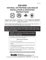
Heat Anticipator Adjustment
The T87F Thermostat has an adjustable heat anticipator.
When the T87F is connected to a zone panel, the heat
anticipator must be set at 0.1A for correct system
operation. When the T87F is connected to a damper in
an independent zone application, the heat anticipator
must be set to 0.4A for proper system operation. See Fig.
5.
Fig. 5. Adjusting heat anticipator.
Checkout
When installation is complete, turn on the power supply
and check thermostat operation using the following
procedure. For complete checkout of entire zone system,
refer to the zone control panel installation instructions.
CAUTION
Equipment Damage Hazard.
Shorting across thermostat terminals of zone
control panels can damage heat anticipator.
Check operation using these instructions.
IMPORTANT
To assure accurate temperature control, do not
touch or breathe on the thermostat bimetal or
thermometer.
Multizone System
HEATING
1. Set each thermostat System switch to Heat and
Fan switch to Auto on the TZ-3, EMM-3, EMM-3U,
EZ-2, and EZ-4.
2. On the MM-2 and MM-3, set zone one thermostat
subbase System switch to heat and Fan switch to
Auto.
3. Turn Zone one thermostat dial 10°F (6°C) above
room temperature to call for heat.
4. Turn dials on all other zone thermostats 20°F (6°C)
below room temperature.
5. Be aware that zone one damper remains open and
all other zone dampers close. (Dampers can take
up to 30 seconds to open or close fully.)
6. Observe that furnace starts immediately and fan
starts after a short delay.
7. To check zones other than zone one, turn the dial
on one of the zone thermostats 10°F (6°C) above
room temperature to call for heat.
8. Be aware that the associated zone damper opens.
9. Turn that zone thermostat dial 10°F (6°C) below
room temperature; damper then closes.
10. Repeat steps 7-9 for each zone other than zone
one.
11. Turn zone one thermostat dial 10°F (6°C) below
room temperature to end call for heat.
12. Unless another thermostat is calling for heat, the
furnace shuts off and the fan shuts off after a short
time. All dampers then open unless set to closed
on the MM-2 or MM-3 panel.
COOLING
1. Set each thermostat System switch to Cool and
Fan switch to Auto on the TZ-3, EMM-3, EMM-3U,
EZ-2 and EZ-4.
2. On the MM-2 and MM-3, set zone one thermostat
subbase System switch to Cool and Fan switch to
Auto.
3. Turn zone one thermostat dial 10°F (6°C) below
room temperature to call for cooling.
4. Turn dials on all other zone thermostats 10°F (6°C)
above room temperature.
5. Be aware that zone one damper remains open; all
other zone dampers close. Dampers can take up to
30 seconds to open or close fully.
6. Observe that cooling and fan come on.
IMPORTANT
To prevent compressor short cycling, a mini-
mum off-time may be included to provide a five-
minute time delay before activating the com-
pressor after the thermostat last turned off the
compressor, or after the system first received
power. This delay protects the compressor.
7. To check zones other than zone one, turn the dial
on one of the zone thermostats 10°F (6°C) below
room temperature to call for cooling.
8. Be aware that the associated zone damper opens.
9. Turn that zone thermostat dial 10°F (6°C) above
room temperature; damper then closes.
10. Repeat steps 7-9 for each zone other than zone
one.
.15 .12
.2
.6
.8
1.0
.5
.4
.3
HOLE SUITABLE FOR
PENCIL POINT
TO MOVE INDICATOR
HEAT
ANTICIPATOR
INDICATOR
SCALE
M1368
A
T87F ZONE THERMOSTAT AND 137421N,P WALLPLATES; T87F ZONE THERMOSTAT AND Q539A,B SUBBASES
5 69-0579-4
11. Turn zone one thermostat dial 10°F (6°C) above
room temperature to end call for cooling.
12. Unless another thermostat is calling for cooling,
cooling and the fan shut off. All dampers then open
unless set to closed on the MM-2 or MM-3 panel.
FAN
1. Set the Fan switch on the zone one thermostat
subbase to On and the System switch to Off.
2. Observe that the fan runs continuously.
3. Move the Fan switch to Auto to control the fan
operation with the plenum fan control in heating
with the thermostat in cooling.
Independent Zone
Use the T87F with the 137421N or P Wallplate for
heat-only independent zone applications.
Use the subbase only to control heating and cooling of
independent zones.
In this application, the T87F controls only the damper
actuator; the thermostat is not connected to the
heating or cooling equipment. A separate thermostat/
subbase is required to control the heating and cooling
equipment. See the thermostat instructions for
heating-cooling equipment checkout.
T87F THERMOSTAT/Q539B SUBBASE
1. With the heating equipment on and Q539B sub-
base System switch set to Heat, turn the thermo-
stat dial 10°F (6°C) above room temperature to call
for heat. The damper opens.
NOTE: The damper can take up to 30 seconds to fully
open or close.
2. Turn the thermostat dial 10°F(6°C) below room
temperature; damper closes.
3. With the cooling equipment on and the Q539B
Subbase System switch set to Cool, turn the ther-
mostat dial 10°F (6°C) below room temperature to
call for cooling; damper opens.
4. Turn the thermostat dial 10°F (6°C) above room
temperature; damper closes.
T87F THERMOSTAT/137421 WALLPLATE
1. With the heating equipment on, turn the thermostat
dial 10°F (6°C) above the room temperature to call
for heat; damper opens.
NOTE: Damper can take up to 30 seconds to fully open
or close.
2. Turn the thermostat dial 10°F (6°C) below room
temperature; damper closes.
Recalibration
The T87F is accurately calibrated at the factory under
controlled conditions and recalibration is not necessary. If
it appear that the thermostat is out of calibration:
1. Make sure the thermostat is level and not sub-
jected to radiant heat from the sun, radiators, or
appliances.
1. Remove the thermostat cover ring to observe the
mercury switch action.
2. After a five- or ten-minute off period (with thermo-
stat setting below room temperature), slowly raise
the setting until the switch just makes contact. If
the thermometer pointer and setting indicator have
the same reading the instant the switch makes, no
recalibration is necessary.
3. If recalibration is necessary: turn the setting dial a
few degrees above room temperature and remove
the cover.
4. Slip the 104994 Calibration Wrench (ordered sepa-
rately) onto the hex under the bimetal coil and,
holding the dial firmly, turn the hex clockwise until
the mercury breaks contact. See Fig. 6.
5. Turn the dial to a low setting so the thermostat
loses the heat it gained from hands and its own
operation. Wait at least five minutes.
6. Slowly turn the dial until the pointers have the
same reading.
7. Firmly holding the dial from turning, carefully turn
the hex counterclockwise until the mercury switch
slips to the heating contact end of the tube.
8. Recheck the calibration, select the desired temper-
ature, and replace the cover.
NOTE: When the T87F provides cooling control, cali-
bration for heating automatically calibrates for
cooling.
Fig. 6. Recalibrating T87F Thermostat.
CAPTIVE
MOUNTING
SCREW (3)
HEAT ANTICIPATOR INDICATOR
ROOM TEMPERATURE SCALE
M19049
CALIBRATION NUT
SETTING SCALE
ADJUSTABLE RANGE
STOPS ON SOME MODELS
T87F ZONE THERMOSTAT AND 137421N,P WALLPLATES; T87F ZONE THERMOSTAT AND Q539A,B SUBBASES
69-0579-4 6
T87F ZONE THERMOSTAT AND 137421N,P WALLPLATES; T87F ZONE THERMOSTAT AND Q539A,B SUBBASES
7 69-0579-4
69-0579-4 G.H. Rev. 08-02 www.honeywell.com/yourhome
T87F ZONE THERMOSTAT AND 137421N,P WALLPLATES; T87F ZONE THERMOSTAT AND Q539A,B SUBBASES
Automation and Control Solutions
Honeywell Honeywell Limited-Honeywell Limitée
1985 Douglas Drive North 35 Dynamic Drive
Golden Valley, MN 55422 Scarborough, Ontario
M1V 4Z9
  • Page 1 1
  • Page 2 2
  • Page 3 3
  • Page 4 4
  • Page 5 5
  • Page 6 6
  • Page 7 7
  • Page 8 8

Honeywell Q539A Installation Instructions Manual

Type
Installation Instructions Manual
This manual is also suitable for

Honeywell Q539A: A Versatile Subbase for Efficient Climate Control

The Honeywell Q539A subbase provides precise temperature management and flexible system control for heating and cooling systems. With its intuitive interface and a range of features, it's an ideal choice for maintaining comfort and energy efficiency in your home. Here's a quick overview of its capabilities:

  • Heating and Cooling System Switching: The Q539A allows you to effortlessly switch between heating and cooling modes, ensuring year-round comfort.

  • Adjustable Fan Control: Choose between automatic fan operation, which adjusts based on system demand, or continuous fan operation for consistent airflow.

Ask a question and I''ll find the answer in the document

Finding information in a document is now easier with AI