Page is loading ...

OWNER'S MANUAL
Use this owner’s manual to reference
installation, troubleshooting and
lter replacement information.
If you need help or have a
question, we’ve got you covered.
Give us a call at
877.333.7108

Owner’s Manual
El manual del proprietario
REVERSE OSMOSIS SYSTEM
Under Sink
AO-US-RO-4000
BAJO EL FREGADERO | SISTEMA DE OSMOSIS INVERSA

TABLE OF CONTENTS
Box Contents ............................................................................................................1
Installation Guide ............................................................................................... 2-10
Troubleshooting Guide ..........................................................................................11
Care and Maintenance ..................................................................................... 12-14
Performance Data Sheet ........................................................................................15
Warranty .................................................................................................................16
Spanish/Español ................................................................................................ 17-37
A. O. Smith has obsessively engineered this ltration system for you. It features ltration
that reduces harmful contaminants – those you can see, smell and taste,
and those you can’t. Whatever your water need – from hydration to cooking, early
morning coffee, smoothies, or soup, you will now have ltered water.
Keep this owner’s manual to reference installation, troubleshooting and lter
replacement information.
If you need help or have a question, we’ve got you covered. Give us a call at
877.333.7108.
REVERSE OSMOSIS SYSTEM
Under Sink
NEED HELP? GIVE US A CALL 877.333.7108
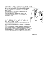
The recommended replacement frequency for the AO-4000-CARBON
is every 6 months or every 365 gallons of use.
The recommended replacement frequency for the AO-RO-RM-R is
every 1 year.
Use only certied, genuine A. O. Smith replacement lters
for continued contaminant removal and system performance.
Visit aosmithatlowes.com to nd replacements or visit your local
Lowe’s store.
year
año
1

NEED HELP? GIVE US A CALL 877.333.7108
Please read entire manual to ensure all parts listed are present before installation.
If any part is missing or damaged let us know by calling 877.333.7108.
Do not attempt to install the lter.
A SYSTEM MANIFOLD
B CARBON FILTER SUMP
C MEMBRANE FILTER
CARTRIDGE
D CLARYUM
®
FILTER SUMP
E REMINERALIZER
F FAUCET WITH TUBING
G ESCUTCHEON (G1), GASKET
(G2), WASHER (G3), NUT (G4)
H WATER STORAGE TANK
1
1
1
2
2
2
3
3
4
4
A
H
F
G
I
J
K
L M N
O
P
Q
R S
T
V
U
W
B C D
E
HOT COLD
A
H
F
B C D
E
P
V
L
Q
J
BOX CONTENTS
1
I EYEDROPPER
J TANK CONNECTOR
K PLUMBER’S TAPE
L DRAIN CONNECTOR
M NUTS & BOLTS
N FOAM SEAL
O FLOW RESTRICTOR (O1)
& 90° ELBOW (O2)
P TUBING
1
⁄4" WHITE
Q TUBING
3
⁄8" RED
R CARBON FILTER CARTRIDGE
S CLARYUM
®
FILTER
CARTRIDGE (BLUE)
T BRACKET
U SCREWS
V BRASS TEE (V1), BRASS
COMPRESSION NUT (V2),
PLASTIC SLEEVE (V3),
BRASS INSERT (V4)
W SUMP WRENCH

NEED HELP? GIVE US A CALL 877.333.7108
• Tape Measure
• Utility Knife
• Phillips Head Screwdriver
•
1
⁄8" &
7
⁄32" Drill Bits/Drill
• Adjustable Wrench
• Bleach
• Safety Glasses
• Pencil
• Masking Tape
• Pan or Bucket
Tools recommended for installation:
Note: We recommend using an approved or certied professional if drilling is required.
Basic plumbing knowledge is recommended prior to installing this unit.
Read the entire manual to familiarize
yourself with the system and determine
the best location for installation. Check
and comply with all local plumbing codes.
1. Prior to installation, turn off the cold
water shut-off valve under the sink.
2. Temporarily place system and tank into the
sink cabinet (or desired location) to ensure
adequate space and proper positioning.
Remove system and tank from under
your sink to begin installation.
Prepare Site and Plan for Installation
Note: If you have metal drain pipes, consult a plumber for installation of drain connection.
WARNING: We recommend using an approved or certied professional.
Proper installation is the responsibility of the installer. Product failure due
to improper installation is not covered under the warranty.
INSTALLATION GUIDE
2
16"
(40.6 cm)
12.875"
(32.7 cm)
6"
(15.2 cm)
11"
(27.9 cm)
12"
(30.5 cm)

NEED HELP? GIVE US A CALL 877.333.7108
INSTALLATION GUIDE
3
Install Brass Tee
1. Turn off COLD water supply.
Turn on kitchen faucet to
release pressure and allow
water to drain from the line.
2. With an adjustable wrench,
disconnect supply line.
3. Attach brass tee (V1) to shutoff
valve and then re-attach COLD
water line to brass tee (3).
Connect Tubing to Brass Tee
1. Attach white tube (P) to the brass tee (V1). Slide brass compression nut (V2)
onto tubing with threads of nut facing end of tube.
2. Slide plastic sleeve (V3) onto tube.
3. Place brass insert (V4) into opening of tube.
4. Push tip of tube into opening of brass tee.
5. While holding tube in place, tighten compression nut to compress plastic
sleeve and create a seal.
1
3
2
1 2 3 4 5
Note: Use a wrench to ensure complete seal. Avoid over-tightening.
Step 1 - Install Brass Tee Fitting
Step 2 - Install System Manifold
Step 3 - Install RO Faucet
Step 4 - Install Water Storage Tank
Step 5 - Install Drain Connector
Step 6 - Connect Tubing
Step 7 - Filter Installation
Step 8 - Sanitize, Test, and Purge
Installation overview
STEP 1 Install Brass Tee Fitting

NEED HELP? GIVE US A CALL 877.333.7108
HOT COLD
1. Select a space under sink that is at least
6" from bottom of your cabinet to allow
for lter replacements. Use mounting
holes located on back of system manifold
(A) to mark wall screw placements.
Ensure holes are level.
2. Use a
1
⁄8" drill bit to drill pilot holes.
Mount unit to wall using two screws (U)
leaving approximately
3
⁄8" of each screw
exposed. Mount system manifold on wall
and screw into place.
3. Mark screw placement of remineralizer
holder 2" away from right side of
system. Using third screw (U), mount
remineralizer holder onto wall.
STEP 2 Install System Manifold
STEP 3 Install RO Faucet
Note: Avoid over tightening
screws. Drilling holes into solid
surfaces or surfaces made of
stone should only be performed
by a certied installer.
You will need the faucet (F) and gasket, nut, washer and escutcheon (G) to complete this step.
Note: Sink top hole must be 1
1
⁄4" diameter for the faucet. If drilling a new hole, ensure faucet
body will mount at against the surface and there is sufcient tubing between faucet and
system manifold.
Note: Save leftover tubing
for a future step.
1. Slide metal escutcheon
(G1) onto faucet base (F)
rst and then black gasket
(G2). Feed tubing and
faucet threads through
countertop hole.
2. Thread metal washer
(G3) onto faucet threads
and then faucet nut
(G4). Tighten faucet
nut by hand.
3. Measure white tubing
attached to faucet to
outlet of remineralizer
and cut to desired length.
INSTALLATION GUIDE
4

NEED HELP? GIVE US A CALL 877.333.7108
INSTALLATION GUIDE
5
Slide nut to threads and
tighten with a wrench.
STEP 4 Install Water Storage Tank
1. Wrap plumber's tape (K) 5 times around
nipple on top of water storage tank (wrap in
same direction as threads - clockwise).
2. Hand-tighten tank connector (J) onto tank
nipple until secure.
Push tubing into
connector through
nut, collar and sleeve.
Unscrew compression
nut from tank connector
to ensure tubing is
connected through
collar and sleeve.
Note: Do not cross-thread or over-tighten.
Note: Do not over-tighten.
3. Use mount stand to place water storage tank near system manifold.
Use remaining 3/8" white tubing saved from Step 3 and connect one end
to the tank.
4. Connect other end of tubing to port labeled "TANK" on system manifold.
FAUCET TANK
System Manifold side view

NEED HELP? GIVE US A CALL 877.333.7108
1. Identify drain outlet location.
STEP 5 Install Drain Connector
HOT COLD
2. Remove protective cover from
back of foam seal (N) and punch
out the center hole.
3. Align holes and attach foam seal to
front plate of drain connector (L).
DRAIN PIPE
BRACKET
NEW HOLE
PRO TIP: If there is leakage from the drain bracket, loosen the bolts and slide the
bracket up so the drilled hole is at the bottom of the drain connector port.
WARNING Ensure all electrical appliances and
outlets are turned off at the circuit breaker before
working in the cabinet area.
CAUTION Wear safety glasses to
protect eyes when drilling.
INSTALLATION GUIDE
6
4. Use drain connector to mark drill
location on drain-line. Position
drain connector on drain pipe
above drain trap allowing room
for drilling.
5. Using a
7
⁄32" drill bit, drill hole into
drain pipe.
6. Securely tighten drain connector
using nuts and screws (M).
WARNING: DO NOT drill hole through
opposite side of pipe.
WARNING: Do not install the drain connector onto the same drain pipe as the garbage disposal. If drain-line must be
installed on the same line as garbage disposal, do not use the drain connector included. A garbage disposal connector
is recommended.

NEED HELP? GIVE US A CALL 877.333.7108
INSTALLATION GUIDE
7
Tubing Do’s
• Insert tubing COMPLETELY to prevent leaking. In most cases, nearly a full
inch will be inserted.
• Wet end of tubing to more easily insert into all inlets and outlets.
• Cut excess tubing in order to prevent crimping, kinks, loops or folds.
Note: Crimping, kinks, loops, and folds can cause leaks or constant noise to come from the
system.
Tubing Dont’s
• DO NOT cut tubing too short. Always double check measurements before cutting.
• DO NOT bend or crimp or kink tubing.
• DO NOT discard excess tubing.
STEP 6 Connect Tubing (Cont. on next page)
Diagram is actual size.
1 2
3

NEED HELP? GIVE US A CALL 877.333.7108
HOT COLD
Brass Tee to Manifold “INLET”
Take ¼" white tubing (P) attached to brass tee and insert into manifold port
labeled “INLET“.
Manifold to Remineralizer
Using
3
⁄8" red tubing (Q), insert one end into system manifold port labeled
”FAUCET”. Insert other end into Remineralizer port labeled ”INLET”.
Remineralizer to Faucet
Take
3
⁄8" white tubing already attached to faucet and connect opposite end to
Remineralizer port labeled ”OUTLET”. This tubing was previously cut to length while
attaching the faucet.
Manifold to Tank
Ensure that the 3/8" white tubing is attached properly to water storage tank and
connected to the system manifold port labeled "TANK" (previously completed in
Step 4).
Air Gap to RO Membrane
• Insert ow restrictor (O1) into end of 1/4" red tubing
attached to faucet (see tubing labeled "5" in
illustration below).
• Attach red tubing to 90° elbow (O2).
• Attach 90° elbow to drain port on membrane
lter cartridge (C).
Faucet to Drain Connector
Take 3/8" red tubing attached to faucet and connect
opposite end to drain connector.
1
4
5
6
2
3
STEP 6 Connect Tubing
INSTALLATION GUIDE
8
3
5
4
1
6
2
WARNING: While completing step 6, to prevent loud noises/vibrations, ensure that none of the tubing is coming into
contact with anything under the sink.
To prevent leaks, refer
to Section 2 on the
troubleshooting guide
(Pg. 11).
TROUBLESHOOTING
TIPS
3
2
1
WARNING:
Faucet will leak
if restrictor is
not installed.
Refer to section 3 of the
troubleshooting guide when
experiencing constant noise
from your system.
TROUBLESHOOTING
TIPS

NEED HELP? GIVE US A CALL 877.333.7108
INSTALLATION GUIDE
9
STEP 7 Filter Installation
Before you begin
Ensure COLD water valve is shut off and there is no water pressure in the system.
Carbon and Claryum
®
lter cartridges will come pre-installed in their cartridge sumps.
1. Attach Stage 1 Carbon lter sump (B) to left (INLET) side of system manifold. Ensure all
connection points are aligned and push sump up into system manifold. Turn sump all
the way to the right until it stops.
Repeat this step for Stage 2 RO Membrane (C) and Stage 3 Claryum
®
lter sump (D).
Stage 1
Stage 1
Stage 2
Stage 3

NEED HELP? GIVE US A CALL 877.333.7108
STEP 8 Sanitize, Test, and Purge
Sanitize
1. Disconnect white tubing from the
manifold outlet labeled “Tank”.
2. Add 3 ml household bleach (5.25%)
into disconnected end of white tubing
using eyedropper (I).
Note: Handle bleach according
to manufacturer’s instructions.
3. Reconnect white tubing to system
manifold outlet labeled ”TANK”.
4. Sanitation will be completed during the
following pressure test and purge.
Important: Bleach must be completely
removed from system before drinking
water. See purge instructions below.
Before you begin
Sanitization is recommended immediately after RO Filter System installation and any
inner-part servicing. The person sanitizing must have clean hands during this process.
Important: Complete sanitization
prior to pressure test.
Pressure Test
1. Turn on COLD water supply valve
to RO Filter System.
2. Turn on kitchen faucet to purge air
from system. Turn off when water
runs smooth.
3. Conrm RO faucet is closed.
4. After 2 hours, pressure will build in the
RO Filter System. Carefully inspect all
connections and ttings while pressure
buildup occurs.
5. Check for leaks. If leaks are found,
ensure all tubing is cut squarely and
fully inserted. Conrm there are no
scratches, dents or notches at tubing
end. If so, squarely cut 1" off of
tubing and re-insert. If leaks are still
happening, refer to trouble shooting
guide.
Your RO Filter System is ready for use
when purge is complete. However,
you will not have ltered water
immediately. It takes 1-3 hours to
completely ll the tank. The ow rate
will be less than your kitchen faucet.
Water will run to the drain while the
RO Filter System is ltering water –
even when not in use. This is normal.
Water going to the drain will stop
automatically when tank is at capacity.
INSTALLATION GUIDE
10
Note: When RO Filter System is rst
pressurized, water may project from
faucet air gap hole until air is passed
from RO Filter System.
Purge
1. Turn on designated faucet and let water
ow through system for 24 hours.
Note: Flow rate will be slow at this time.
2. Turn off RO faucet after purge
is complete.
IMPORTANT

NEED HELP? GIVE US A CALL 877.333.7108
TROUBLESHOOTING GUIDE
11
PROBLEM POSSIBLE CAUSE SOLUTION
1
Leaking
from
Sumps
O-ring not sealed
due to sump cap
undertightening
Turn off water supply. Remove leaking sump from system manifold.
Using provided sump wrench, gently turn the sump cap clockwise until
it stops to position O-ring in optimal seal position. Be careful not to
overtighten as this can also cause leaking.
Sumps
overtightened
creating a pinch
in the O-Ring
Turn off water supply. Remove leaking sump from system
manifold. Using provided sump wrench, gently turn the sump cap
counterclockwise to disconnect sump cap. Check O-ring for damage in
the form of cuts or abrasions. Check threads on sump for damage. If
either part is damaged, contact customer service. If there is no damage,
using provided sump wrench, gently turn the sump cap clockwise until it
stops to position O-ring in optimal seal position. Do not overtighten.
2
Leaking
from
Key Hole
Drain line
is kinked
Refer to tubing diagram on Pg. 8. Check red tube marked “6”
for kinks that could constrict water ow. Also check for loops.
This line is not pressurized. Water needs a straight path for gravity
to force water down the drain.
Obstruction in
the drain line
Refer to tubing diagram on Pg. 8.
Turn off water supply.
Look into the red tube marked “6” to see if there are any obstructions
clogging the line. Using a pipe cleaner or thin bottle brush,
try to remove the obstruction.
If unable to clean the line, cut the tubing to the obstruction, remove
the obstruction, and reconnect the tubing. STOP: Before cutting tubing,
make sure there is enough tubing to reconnect lines.
3
Constant
Noise /
Loud
Noise
Flow restrictor not
installed, water
continuosly leaking
down the drain line
Refer to ow restrictor diagram on Pg. 8. Turn off water supply.
Remove the 90 degree elbow from the RO Membrane and check for the
small insert within tubing marked “5”. If insert is missing, place ow
restrictor into tubing and reconnect tubing and elbow to RO membrane.
Tubing causing
vibrations against
objects
Check to see if any tubing is in direct contact with anything under the
sink. Tubing can move while the water is running through the system
causing vibrations. Turn off water supply and move tubing if necessary.
4
This is a 4-stage Reverse Osmosis system. This system is not powered and uses the regular ow of
water pressure to force water through the ltration process. If you feel that the ow of water from
your dedicated faucet is abnormally slow, follow the steps below to troubleshoot.
Slow
Flow
Low Water Pressure
Using a water pressure gauge (not provided), test incoming water pressure
to ensure pressure is at least 40 psi. Best performance is at 60 psi.
Sumps not fully
engaged in
manifold
Refer to diagram on Pg. 9. Turn off water supply.
Turn sump all the way to the right until it stops.
Tank pressure is
not between
5-7 psi
Refer to diagram on Pg. 5. Turn off water supply. Drain RO tank
completely by opening the dedicated faucet and releasing water until
it stops. Disconnect the tank connector from the tank and turn it upside
down to ensure all water has been removed.
Using a digital pressure gauge (not provided), check the tank pressure
to ensure it is between 5-7 psi. If the pressure is too low, use a bike
pump to add pressure in the small nozzle at the bottom of the tank.
If pressure is too high, you can press down the pin to release
pressure until optimal psi is achieved.

NEED HELP? GIVE US A CALL 877.333.7108
AO-US-RO-4000
Replacement cartridge AO-4000-CARBON
and AO-RO-RM-R
Membrane TDS Reduction
1
95% minimum
TDS Reduction
2
96.3%+ average
Max TDS 1000 ppm
Max water hardness @ 6.9pH 10 gpg (2.64 gpL)
Max Chlorine in water 3.0 ppm
Supply water pH limits 4-10
Drain (reject water) Flow 3-5x product ow
Empty Storage Tank Precharge 5-7 psi air (35-48 kPa)
Storage Tank Capacity
2
3.2 gallons (12.11 liters)
Supply water pressure limits 40-100 psi (275-689 kPa)
Supply water temperature limit 40-90° F (5-32° C)
Specications – Qualied System
Performance
Because the performance of a Reverse
Osmosis Membrane is highly dependent
upon pressure, temperature and Total
Dissolved Solids (TDS), the following should
be used for comparison purposes only.
Industry standards measure RO Membranes
performance with no back pressure on the
product water, at 60 psi (414 kPa) and 77°F
(25°C). Further conditions on the above are
250 ppm TDS and a 30.6% recovery rate.
Production rate and TDS reduction gures
are for a new Membrane that has been
rinsed for 24 hours. The production rate of
a new Membrane can decrease by 10% per
year or more, depending upon the scaling
and fouling tendencies of the Feed Water.
Measured at 50 psi, 77°±2°F, and 717 mg/l
TDS per NSF/ANSI Standard 58.
Efciency rating is the percentage of the
inuent water to the system that is available
to the user as reverse osmosis treated water.
This measurement is taken under operating
conditions that approximate typical
daily usage.
Recovery rating is the percentage of the
inuent water to the membrane portion
of the system that is available to the user
as reverse osmosis treated water when the
system is operated without a storage Tank
or when the storage Tank is bypassed.
CAPACITY AT VARIOUS WATER PRESSURE LEVELS (WITH 5 PSI PRECHARGE) U.S. GALLONS
TOTAL VOLUME 20 PSI 30 PSI 40 PSI 50 PSI 60 PSI 70 PSI
3.2 1.4 1.8 2.0 2.2 2.4 2.5
NON-POTABLE WATER SOURCES: Do not attempt to use this product to make safe drinking water from non-potable water sources.
Do not use the system on microbiologically unsafe water, or water of unknown quality without adequate disinfection before or after the
system. This system is certied for cyst reduction and may be used on disinfected water that may contain lterable cysts.
INSTALLATIONS IN THE COMMONWEALTH OF MASSACHUSETTS: The Commonwealth of Massachusetts requires installation be
performed by a licensed plumber and does not permit the use of saddle valves. Plumbing code 248—CMR of the Commonwealth of
Massachusetts must be followed in these cases.
Do not use with water that is microbiologically unsafe or of unknown water quality without adequate disinfection before or after the system.
Systems certied for cyst reduction may be used on disinfected waters that may contain lterable cysts.
Filter is only to be used with cold water. Systems certied for cyst reduction may be used on disinfected water that may contain lterable cysts.
CARE AND MAINTENANCE
12

NEED HELP? GIVE US A CALL 877.333.7108
Nitrate/Nitrite Test Kit:
This system is acceptable for treatment
of inuent concentration of no more
than 27 mg/L nitrate and 3 mg/L nitrite in
combination measured as N.* This system
is supplied with a nitrate/nitrite test kit.
Product water should be monitored
periodically according to the instructions
provided with the test kit.
Drain Flow Restrictor
The restrictor is vital for proper operation of
RO Membrane Cartridge as it keeps water
owing through the membrane at the
proper rate ensuring the water produced
is the best quality. It is recommended the
restrictor assembly be periodically inspected
to be sure it is clean and unrestricted.
If service is required on the drain ow
assembly, disassemble and reassemble as
outlined in Step 6.
Flow rate and output are determined
by 3 factors:
1 Incoming water temperature
2 Total dissolved solids (TDS) present
in supply water
3 Incoming water pressure
Lower temperatures are directly
proportional to slower ow rate. All
membranes are tested at 77°F. Incoming
water temperature should not exceed
90°F (32° C). The RO Filter System
should also not be installed in a location
susceptible to freezing. The more TDS in
the supply water, the more lter time is
required. Incoming TDS should not exceed
1000 ppm. Higher water pressure enables
a higher ow rate. Pressure must be above
40 psi for proper system operation. You
may consider installing a booster pump if
your pressure is below 40 psi.
Carbon Pre-Filter and Claryum
®
Post-Filter
Change every 6 months*
The Carbon and Claryum
®
lter cartridges
are replaceable activated carbon
cartridges located in Stages 1 and 3. It is
recommended to replace these cartridges
at least every 6 months. You may need to
replace more often with high water usage
or high sediment level. Timely replacement
of these cartridges will protect the RO
Membrane from high levels of chlorine
and/or sediment. As these lters build up
with sediment, you may notice slower
water output.
RO Membrane Cartridge
Change every 12 months*
The RO Membrane is located in Stage 2.
This membrane reduces the dissolved solids
and organic matter. Most municipally
treated water has a 7.0-7.5 pH, in this
case you would need to replace your RO
Membrane every 12 months. Membrane
life depends on pH and supply water
hardness. Higher pH shortens membrane
life by causing pin-hole leaks. When
output, water quality, and production rate
decrease, it is time to replace the lter.
Remineralizer
Change every 12 months*
The Remineralizer is Stage 4. It is designed
to provide healthy amounts of calcium,
magnesium and potassium for great-
tasting water.
*Filter life depends on water usage and
water supply quality.
CARE AND MAINTENANCE
13

Arsenic (abbreviated As) is found naturally
in some well water. Arsenic in water has
no color, taste or odor. It is measured by
a laboratory test. Public water utilities
must have their water tested for arsenic.
You can get the results from your water
utility. If you have your own well, you can
have the water tested. The local health
department or the state environmental
health agency can provide a list of certied
labs. Information about arsenic in water
can be found on the internet at the U.S.
Environmental Protection Agency website:
epa.gov/safewater/arsenic
There are two forms of arsenic:
pentavalent arsenic (As(V), As(+5), and
arsenate) and trivalent arsenic (also called
As(III), As(+3), and arsenite). In well water,
arsenic may be pentavalent, trivalent, or
a combination of both. Special sampling
procedures are needed for a lab to
determine what type and how much of
each type of arsenic is in the water. Check
with the labs in your area to see if they can
provide this type of service.
Reverse Osmosis (RO) water treatment
systems do not completely remove
trivalent arsenic from water. RO systems
are very effective at removing pentavalent
arsenic. A free chlorine residual will rapidly
convert trivalent arsenic to pentavalent
arsenic. Other water treatment
chemicals such as ozone and potassium
permanganate will also change trivalent
arsenic to pentavalent arsenic. A combined
chlorine residual (also called chloramine)
may not convert all to trivalent arsenic. If
you get your water from a public water
utility, contact the utility to nd out if
free chlorine or combined chlorine is used
in the water system. The AO-US-RO-4000
System is designed to remove pentavalent
arsenic. It will not convert trivalent arsenic
to pentavalent arsenic. This System was
tested in a lab. Under testing conditions,
the system reduced [0.30 mg/L (ppm) or
0.050 mg/L (ppm)] pentavalent arsenic to
0.010 mg/L (ppm) (the USEPA standard for
drinking water) or less. The performance
of the system may be different with your
installation. Have your treated water
tested for arsenic to check whether the
system is working properly.
The RO component of the AO-US-
RO-4000 System must be replaced every
1-3 years to ensure the system will
continue to remove pentavalent arsenic.
The component identication and
locations where you can purchase the
component are listed in the installation/
operation manual.
This system has been tested for the treatment of water containing pentavalent arsenic
(also known as As(V), As(+5), or arsenate) at concentrations of 0.30 mg/L or less. This system
reduces pentavalent arsenic, but may not remove other forms of arsenic. This system is
to be used on water supplies containing a detectable free chlorine residual at the system
inlet or on water supplies that have been demonstrated to contain only pentavalent
arsenic. Treatment with chloramine (combined chlorine) is not sufcient to ensure complete
conversion of trivalent arsenic to pentavalent arsenic. Please see the Arsenic Facts section
of this Performance Data Sheet for further information.
• Efciency rating is the percentage of
the inuent water to the system that
is available to the user as reverse
osmosis treated water under operating
conditions that approximate typical
daily usage.
• Recovery rating is the percentage of
the inuent water to the membrane
portion of the system that is available
to the user as reverse osmosis treated
water when the system is operated
without a storage Tank or when the
storage Tank is bypassed.
Arsenic Facts
CARE AND MAINTENANCE
14
NEED HELP? GIVE US A CALL 877.333.7108

Organic chemicals included by surrogate testing
VOCs
(by surrogate testing
using chloroform)
Drinking
water
regulatory
level (MCL/
MAC) mg/L
Inuent/
Unltered
Efuent/
Filtered
Percent
Reduction
alachlor 0.002 0.050 0.001 >98%
atrazine 0.003 0.100 0.003 >97%
benzene 0.005 0.081 0.001 >99%
carbofuran 0.04 0.190 0.001 >99%
carbon tetrachloride 0.005 0.078 0.0018 98%
chlorobenzene 0.1 0.077 0.001 >99%
chloropicrin — 0.015 0.0002 99%
2,4-D 0.07 0.110 0.0017 98%
dibromochloropropane (DBCP) 0.0002 0.052 0.00002 >99%
o-dichlorobenzene 0.6 0.080 0.001 >99%
p-dichlorobenzene 0.075 0.040 0.001 >98%
1,2-dichloroethane 0.005 0.088 0.0048 95%
1,1-dichloroethylene 0.007 0.083 0.001 >99%
cis-1,2-dichloroethylene 0.07 0.170 0.0005 >99%
trans-1,2-dichloroethylene 0.1 0.086 0.001 >99%
1,2-dichloropropane 0.005 0.080 0.001 >99%
cis-1,3-dichloropropylene — 0.079 0.001 >99%
dinoseb 0.007 0.170 0.0002 99%
endrin 0.002 0.053 0.00059 99%
ethylbenzene 0.7 0.088 0.001 >99%
ethylene dibromide (EDB) 0.00005 0.044 0.00002 >99%
haloacetonitriles (HAN)
Inuent/
Unltered
Efuent/
Filtered
Percent
Reduction
bromochloroacetontrile — 0.022 0.0005 98%
dibromoacetontrile — 0.024 0.0006 98%
dichloroacetontrile — 0.0096 0.0002 98%
trichloroacetontrile — 0.015 0.0003 98%
haloketones (HK)
Inuent/
Unltered
Efuent/
Filtered
Percent
Reduction
1,1-dichloro-2-propanone — 0.0072 0.0001 99%
1,1,1-trichloro-2-propanone — 0.0082 0.0003 96%
heptachlor (H-34, Heptox) 0.0004 0.025 0.00001 >99%
heptachlor epoxide 0.0002 0.0107 0.0002 98%
hexachlorobutadiene — 0.044 0.001 >98%
hexachlorocyclopentadiene 0.05 0.060 0.000002 >99%
lindane 0.0002 0.055 0.00001 >99%
methoxychlor 0.04 0.050 0.0001 >99%
pentachlorophenol 0.001 0.096 0.001 >99%
simazine 0.004 0.120 0.004 >97%
styrene 0.1 0.150 0.0005 >99%
1,1,2,2-tetrachloroethane — 0.081 0.001 >99%
tetrachloroethylene 0.005 0.081 0.001 >99%
toluene 1 0.078 0.001 >99%
2,4,5-TP (silvex) 0.05 0.270 0.0016 99%
tribromoacetic acid — 0.042 0.001 >98%
1,2,4-trichlorobenzene 0.07 0.160 0.0005 >99%
1,1,1-trichloroethane 0.2 0.084 0.0046 95%
1,1,2-trichloroethane 0.005 0.150 0.0005 >99%
trichloroethylene 0.005 0.180 0.0010 >99%
trihalomethanes (THMs)
Inuent/
Unltered
Efuent/
Filtered
Percent
Reduction
bromodichloromethane (THM)
0.080 0.300 0.015 95%
bromoform (THM)
chloroform (THM)
chlorodibromomethane (THM)
xylenes (total) 10 0.070 0.001 >99%
NSF/ANSI 42 Minimum Reduction Overall % Reduction Results
Chlorine Reduction, Free Available
<0.5 mg/l 97.66% Pass
Chloramine Reduction, Free Available
<0.5 mg/l 97.66% Pass
Particulate Reduction 85% 99.9% Pass
NSF/ANSI 53 Minimum Reduction Overall % Reduction Results
Cyst Live Cryptosporidium & Giardia 99.95% >99.99% Pass
Mercury Reduction pH 8.5 <2 ug/L >95.8% Pass
Mercury Reduction pH 6.5 <2 ug/L >96.5% Pass
Lead Reduction pH 6.5 <10 ug/L >99.4% Pass
Lead Reduction pH 8.5 <10 ug/L >99.3% Pass
MTBE Reduction <5 ug/L 86.6% Pass
Turbidity <0.5 NTU 99.1% Pass
VOC Surrogate Test 95% 99.4% Pass
Asbestos 99% >99% Pass
Peruorooctanoic acid (PFOA) &
Peruorooctane sulfonate (PFOS)
0.07 ug/L 95.8% Pass
NSF/ANSI 58
Maximum
Concentration
Minimum
Reduction
Overall % Reduction Results
Arsenic Pentavalent 0.30mg/L ± 10% 80.0% 97.6% Pass
Barium 10.0mg/L ± 10% 80.0% 95.2% Pass
Cadmium 0.30mg/L ± 10% 83.3% 95.3% Pass
Chromium Hexavalent 0.30mg/L ± 10% 66.7% 97.0% Pass
Chromium Trivalent 0.30mg/L ± 10% 66.7% 96.6% Pass
Copper 0.30mg/L ± 10% 56.7% 96.6% Pass
Fluoride 8.0mg/L ± 10% 81 .2% 95.7% Pass
Lead .15mg/L ± 10% 93.3% 96.6% Pass
Nitrate/Nitrite 30.0mg/L ± 10% 66.7% 82.4% Pass
Radium 226/228 25pCi/L ± 10% 80.0% 80.0% Pass
Selenium 0.10mg/L ± 10% 50.0% 97.9% Pass
TDS 750mg/L ± 10% 75.0% 95.0% Pass
Turbidity 11 ± NTU 95.4% 99.1% Pass
NSF/ANSI 401
Maximum
Concentration
Minimum Reduction Overall % Reduction Results
Atenolol 30 ng/L 94.2% 94.2% Pass
Bisphenol A 300 ng/L 98.80% 98.9% Pass
Carbamazepine 200 ng/L 98.6% 98.6% Pass
DEET 200 ng/L 98.7% 98.7% Pass
Estrone 20 ng/L 96.30% 96.5% Pass
Ibuprofen 60 ng/L 95.3% 95.4% Pass
Linuron 20 ng/L 96.6% 96.6% Pass
Meprobamate 60 ng/L 94.7% 94.7% Pass
Metolachlor 200 ng/L 98.6% 98.6% Pass
Naproxen 20 ng/L 96.3% 96.4% Pass
Nonyl phenol 200 ng/L 97.50% 97.5% Pass
Phenytoin 30 ng/L 95.50% 95.6% Pass
TCEP 700 ng/L 98% 98% Pass
TCPP 700 ng/L 97.8% 97.8% Pass
Trimethoprim 20 ng/L 96.7% 96.7% Pass
For use with municipally treated water only. Do not use with
water that is microbiologically unsafe or of unknown water
quality without adequate disinfection before or after the system.
Filter is only to be used
with cold water.
Filter usage must comply
with all state and local laws.
Testing was performed under
standard laboratory conditions,
actual performance may vary.
Systems certied for cyst reduction
may be used on disinfected waters
that may contain lterable cysts.
See owner’s manual for general
installation conditions and needs plus
manufacturer’s limited warranty.
• All contaminants reduced by this lter are listed.
• Not all contaminants listed may be present in your water.
• Does not remove all contaminants that may be present in tap water.
Testing performed against NSF/ANSI Standards 42, 53, 58 and 401 and in accordance with the California Department of Health Services Drinking Water Treatment Device
Program. This system has been tested according to NSF/ANSI Standards 42, 53, 58 and 401 for the reduction of the substances listed below. The concentration of the indicated
substances in water entering the system was reduced to a concentration less than or equal to the permissible limit for water leaving the system, as specied in NSF/ANSI 42,
53, 58, and 401.
Performance Data for the Drinking Water System AO-US-RO-4000
Manufactured by: A. O. Smith Corporation P.O. Box 1597 | Johnson City, TN 37605-1597 | 877.333.71088
Models Replacement Operating
pressure range
Operating
temp. range
Recovery
rating
Efciency
rating
Daily
Production (DPR)
AO-US-
RO-4000
AO-4000-CARBON
and AO-RO-RM-R
40-100 psi
275-689 kPa
40-90° F
4.44-32.2° C
29.43% 17.91% 13.32 gallons
50.4 liters
System Tested and Certied by NSF
International against NSF/ANSI Standards
42, 53, 58 and 401 for the reduction of
the claims specied on the Performance
Data Sheet and at www.nsf.org.

What is covered:
This warranty covers defects in materials
or workmanship in manufacturing of
your A. O. Smith drinking water lter
systems, except as provided below.
For how long:
This warranty runs for two years from
the date of purchase by a consumer
(“Warranty Period”).
What is not covered:
This warranty does not cover lter
cartridges and/or any products that
were not installed in compliance with
the instructions or that have been
abused or operated incorrectly. The
limited warranty stated herein is in lieu
of any and all warranties, expressed
or implied, whether written or oral,
including but not limited to the implied
warranties of tness for a particular
purpose or the implied warranty of
merchantability. A. O. Smith shall not be
liable for any incidental, consequential,
special or contingent damages arising
directly or indirectly from any defect or
the use of the system. Owner shall be
responsible for all labor and any other
expenses related to the removal, repair
or installation of the ltration system
or any component part. Finally, this
warranty is voided if the product is
used with parts that are not genuine
A. O. Smith parts. This includes, but
is not limited to: replacement lters,
faucets, and diverter valves.
What A. O. Smith will do:
We will replace the defective part of
the covered product and send it to you
upon payment of $9.50 for shipping and
handling per incident.
How to get service:
To receive service under this
warranty, you must contact
A. O. Smith at 1-877-333-7108 or
aosmithatlowes.com/contactus within
the Warranty Period and describe
the problem to a customer service
representative who will verify that the
product is under warranty and arrange
for delivery of a replacement part.
How state law applies:
This warranty gives you specic rights
but you may have other rights which
vary from state to state.
Some states do not allow the exclusion
or limitation of implied warranties or
incidental or consequential damages,
so the above limitation or exclusion
may not apply to you.
Warranty card:
Warranty registration is not required
for coverage under the A. O. Smith
Limited Warranty. If you purchased from
a retailer or dealer, please complete
the online warranty registration form
at aosmithatlowes.com/register. Once
registered online, we will have a record
of your purchase and you will not be
required to produce a proof of purchase
for a warranty claim.
A. O. Smith Corporation P.O. Box 1597 | Johnson City, TN 37605-1597 | 877.333.7108
LIMITED WARRANTY
2
YEAR

A.O.Smith diseñó este sistema de ltración minuciosamente para usted. Cuenta con
ltración que disminuye los contaminantes dañinos, aquellos que puede y no puede ver,
oler y sentir su sabor. Sin importar para qué necesite el agua, para hidratarse, cocinar,
para el café de la mañana, los batidos o una sopa, ahora tendrá agua ltrada.
Conserve este manual del propietario como referencia para la instalación, resolución de
problemas e información de reemplazo del ltro.
La frecuencia de reemplazo recomendada para el
AO-4000-CARBON es cada 6 meses o cada 1,382litros
(365galones) de uso.
La frecuencia de reemplazo recomendada para
el AO-RO-RM-R es cada 1 año.
Solo use ltros de repuesto originales A.O.Smith y
certicados para eliminación de contaminantes y rendimiento
del sistema constantes.
Visite aosmithatlowes.com para encontrar repuestos o visite
su tienda local Lowe’s.
year
año
1
/