TS75(A)-B7132 Quick Installation Guide
Document # D2573-100/ Revision 1.0
5618B0060001
Phillips Screwdriver Anti-Static Wrist Strap
Tools Required
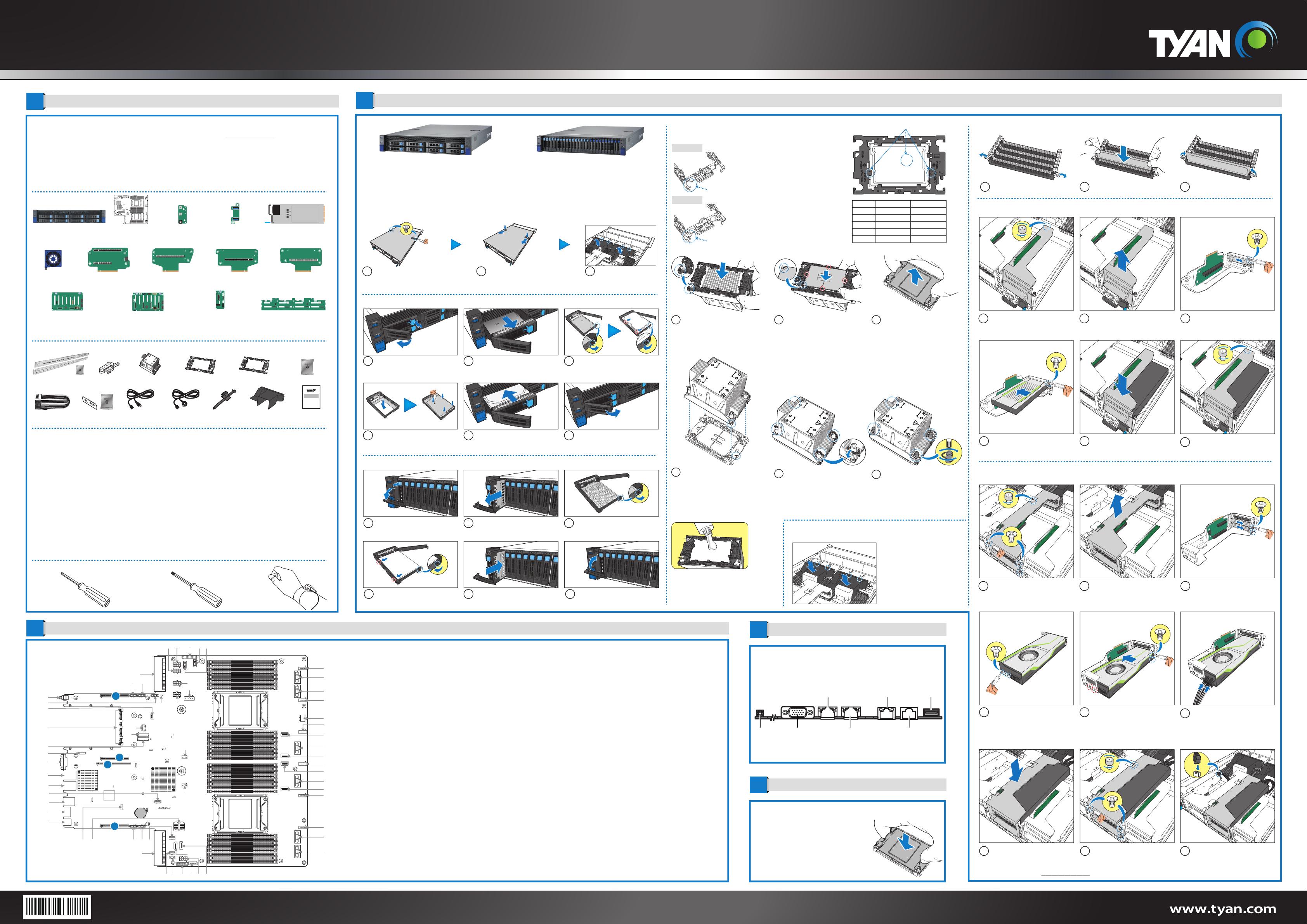
1General Information 3System Installation
2Motherboard Placement
5Caution
Motherboard Placement
CPU Cover for DOA/RMA
Locate the External I/O Port
Minimum Hardware Requirements
To avoid integration difficulties and possible board damage, your system must meet the following minimum requirements:
• Processor: (2) Intel® Xeon® Eagle Stream (Sapphire Rapids-SP) series processor with TDP up to 350W
• Memory Type:
- (16+16) DIMM slots, (L)RDDR5 up to 4800 with ECC (1.2V)
- (8) memory channels per CPU, (16) DIMM slots per CPU channel
• Hard Disk Drives:
- B7132T75E8HR:
(8) 3.5"SAS 12GB/s & SATA 6GB/s and NVMe compatible hot-swap, tool-less HDD drive bays
- B7132T75AV10E16HR:
(8) 2.5" SAS 12GB/s & SATA 6GB/s hot-swap, tool-less HDD drive bays
(8+8) 2.5" NVMe hot-swap, tool-less HDD drive bays
(2) 2.5" NVMe hot-swap, tool-less HDD drive bays
• Rack Mount Kit (Industry 19" rack-mountable)
NOTE: The updated hardware requirements of the system please refer to the barebones user’s manual on our website at www.tyan.com
Required Hardware Components
Preparing the Chassis
Read normal ESD (Electrostatic Discharge) procedures.
Place your TYAN® Server Chassis on a flat anti-static surface to perform the following integration procedures. Read
ESD procedures before reaching inside to install components.
Open the Chassis
4I/O Ports
NOTE: Please save and replace the PnP Cap
when returning the server board for service.
T30 Security Torx Screwdriver
CONNECTORS
1
System Power Connector0 (J24)
2
4-pin Power Connector (J45)
3
4-pin Power Connector (J44)
4
ID Button (SW2)
5
4-pin Power Connector (J42)
6
SPI TPM Connector(J16)
7
OCP 3.0 (J1_OCP3)
8
M.2 Connector (CN2) PCIE ONLY
9
Front VGA Header (J37)
10
Rear VGA Header (J36)
11
RJ45 LAN Port (LAN1)
12
RJ45 LAN Port (LAN2)
13
TYPE A USB3.2 Gen1 Header (J28)
14
Dedicated to IPMI (J8)
15
BIOS COM Port (J7)
16
USB3.1 Gen1 Header (J31)
17
ESPI Port 80 Header (J38)
18
Mini SAS HD Connector (MINI_SAS_HD1)
19
4-pin Power Connector (J11)
20
4-pin Power Connector (J43)
21
HDD BP SMbus Header (J10)
22
System Power Connector1 (J25)
23
HDD BP SMbus Header (J17)
24
HDD BP SMbus Connector (J9)
25
Front USB3.0&2.0 Connector (J5)
26
Front Fan Header (FAN_HD1)
27
8-pin Power Connector (J35)
28
SATA DOM (J26)
29
MCIOx8 NVME (J52)
30
MCIOx8 NVME (J53)
31
Fan Connector (SYS_FAN_6)
32
Fan Connector (SYS_FAN_5)
SLOTS
A
PCIE#1 x16(J1) CPU0 P2:0~15
B
PCIE#2 x20 (J46) CPU0: PE1 0~15 and PE0 8~11
C
PCIE#3 x16(J3) CPU1 P2:0~15
D
PCIE#4 x16(J2) CPU1 P0 :0~15
33
MCIOx4 NVME (CN11)
34
MCIOx8 NVME (J60)
35
MCIOx4 NVME (CN10)
36
Fan Connector (SYS_FAN_4)
37
MCIOx4 NVME (CN6)
38
MCIOx8 NVME (J58)
39
MCIOx4 NVME (CN7)
40
Fan Connector (SYS_FAN_3)
41
8-pin Power Connector (J56)
42
Fan Connector (SYS_FAN_2)
43
MCIOx8 NVME (J62)
44
MCIOx8 NVME (J61)
45
Fan Connector (SYS_FAN_1)
46
8-pin Power Connector (J41)
47
8-pin Power Connector (J55)
48
Front Panel Header (J22)
JUMPERS
a
CMOS Clear Jumper (J6_PCH)
b
CPLD Power On Jumper (J2_FPGA)
c
BMC Reader Jumper (J18)
d
ME Recovery Jumper (J3_PCH)
e
BIOS Core Execution Tree Jumper (J5_PCH)
f
BMC Remote Debug Jumper (J19)
g
Top Swap Disabled Jumper (J1_PCH)
h
Password Clear Jumper (J2_PCH)
i
Manufacture Mode Jumper (J4_PCH)
LEDs
i
CPLD HeartBeat LED (D33)
ii
PLTRST LED (D41)
iii
SYSTEM PWROK LED (D82)
iv
BMC HeartBeat LED (D1_BMC)
49
8-pin Power Connector (J12)
50
8-pin Power Connector (J34)
51
8-pin Power Connector (J32)
52
4-pin Power Connector (J40)
53
8-pin Power Connector (J33)
54
Intrusion Header (J1_FPGA)
55
CPLD JTAG Header (J3_FPGA)
56
M.2 Connector (CN1) PCIE ONLY
57
CPU1_FAN (J4)
58
CPU0_FAN (J47)
59
SATA DOM (J27)
B7132T75E8HR B7132T75AV10E16HR
(1) M.2 Card
Latch
3Lock the clips.
2Insert the memory module.
1Unlock the clips.
1Remove the two screws
securing the top cover to the
chassis.
3Lift to remove the air ducts
from the chassis.
2Press firmly the locking
latches, then slide to remove
the top cover.
Install the Front Hard Disk Drives (3.5” or 2.5”)
3b Place a 2.5” hard HDD into the
drive tray. Use 4 screws to secure
the HDD to the tray.
3a Unlock and open the tray locking
lever. Place the 3.5” HDD into the
drive tray. Close the locking lever to
secure the HDD to the tray.
1Press on the locking lever latch.
The locking lever opens
automatically.
2Slide the HDD tray out.
4Reinsert the HDD tray into the
chassis. 5Press the locking lever to secure the
tray. Repeat the same procedures
to install other HDD trays.
Install the Front Hard Disk Drives (2.5”)
4Install the 2.5” HDD into the pins on
the drive tray. Close the locking
lever to secure the HDD to the tray.
1Press on the locking lever latch.
The locking lever opens
automatically.
012345678
3Unlock and open the tray locking
lever.
6Press the locking lever to secure the
tray. Repeat the same procedures
to install other HDD trays.
012345678
2Slide the HDD tray out.
5Reinsert the HDD tray into the
chassis.
012345678
012345678
Install the Processor
Install the Air Duct
By aligning with the guide pins,
place the CPU0 air duct on top of
the CPU0 heatsink.
Repeat the step for installing the
CPU1 air duct.
NOTE: A new heatsink comes with pre-applied
thermal grease.
Once the heatsink has been removed from the
processor, you need to clean the processor and
heatsink using an alcohol solvent. Then apply new
thermal grease before reinstalling the heatsink.
4Carefully flip the heatsink assembly.
Align the heatsink with the CPU
socket by the guide pins. Make also
sure that the triangle edge of the
carrier is aligned correctly with the
triangle mark on the CPU socket.
Then place the heatsink assembly
onto the top of the CPU socket.
1Align the triangle edge of the carrier
with the notch on the edge of the
heatsink. Then install the carrier on
the bottom of the heatsink and make
sure the latches are snapped under
the edge of the heatsink.
2Align and install the processor on
the carrier. Make sure the gold
arrow is located in the correct
direction.
NOTE: When installing the
processor, secure the front side (A)
first, and following with the middle
and rear sides (BC).
3Remove the CPU cover.
A
B
B
C
5Press down on the retention clips
to fix the heatsink assembly to the
CPU socket.
6To secure the heatsink assembly,
use a T30 Security Torx to tighten
the screws.
E1A
Visual Indicators
Package Type
Shim
Carrier code
TE
FIT
LOTES
XCC
NO
E1A
1-2351052-5
WNMEC00-0NNK1-EH
AZIF0204-P006C
MCC
YES
E1B
1-2351052-2
WNMEC00-0NNK2-EH
AZIF0240-P003C
Shim Concept
XCC carrier
MCC carrier
Shim installed in package carrier to offset the spring deflection.
No Shim case
NOTE: Please refer to http://www.tyan.com for supported GPU list.
Install the Dual Slot GPU Card (Optional)
1 2 3
456
7 8 9
Install the Single Slot GPU Card (Optional)
Install the Single Slot GPU Card (Optional)
1 2 3
456
Release the thumbscrew securing
the GPU bracket to the chassis.
Lift to remove the GPU bracket from
the chassis.
Flip the GPU bracket and place on
the surface. Then remove the screw
and slide to remove the dummy
bracket.
Install the GPU card to the GPU
bracket, and then secure the GPU
card to the bracket with a screw.
Carefully flip the GPU bracket. Then
align and install the GPU bracket to
its slot on the chassis.
Tighten the thumbscrew to secure
the GPU bracket to the chassis.
Release the thumbscrew and
remove the three screws securing
the GPU bracket to the chassis.
Lift to remove the GPU bracket from
the chassis.
Flip the GPU bracket and place on
the surface. Then remove the two
screws and slide to remove the
dummy brackets.
Align and install the GPU card
holder plate to the GPU card. Then
secure it with the two or three long
screws.
Install the GPU card to the GPU
bracket, and then secure the GPU
card to the bracket with the four
screws (2 screws for the front side of
the bracket and 2 short screws for
the rear side of the bracket).
Connect the GPU cable (2-in-1) to
the GPU card connectors.
Carefully flip the GPU bracket. Then
align and install the GPU bracket to
its slot on the chassis.
Tighten the thumbscrew and install
the three screws to secure the GPU
bracket to the chassis.
Connect the other end of the GPU
cable to the motherboard
connector.
(2) CPU Heatsink (2) MCC CPU
carrier
(2) XCC CPU
carrier
Read Me First
1. The Barebone User’s Manual is available for download from our Web site at http://www.tyan.com. Make sure to read all
precautions and instructions before you start installing the server system.
2. Refer all servicing to qualified personnel to avoid the risk of damage to the server system.
3. Exercise normal ESD (Electrostatic Discharge) procedures during system integration. TYAN/MiTAC recommends wearing
gloves and an anti-static wrist strap to avoid possible damage to the equipment.
4. Current processor socket design places the pins on the motherboard instead of the processor itself. Exercise caution when
installing the processors as the manufacturer’s warranty does not cover damage inflicted upon the motherboard, including
damage to the CPU sockets.
Box Content
Accessories
(1) 2U chassis
(1) TYAN Quick
Installation Guide
Quick Installation
Guide
(1) Rail Kit and Screw
(2) Power
Wire Mount
(1) M1718T65-FPB
Front Panel Board
(pre-installed)
(1) M1717T65-USB
USB Board
(pre-installed)
(2) 1600W Power Supply
Units (pre-installed)
(1) M1318T65-BP12E-2
Front HDD Backplane
Board (pre-installed
for B7132T75AV10E16HR)
(2) GPU
Power Cable
(2) GPU Card
Bracket Kit
(1) 2.5 HDD Screws
(6) 60X60X38mm
Fan (pre-installed)
(1) M7132T75-R16-1F
Riser Card (pre-installed)
(2) EU
Power Cord
(2) US
Power Cord
(1) TYAN® S7132
System Board
(pre-installed)
(1) M1321T70A-BP12-8 HDD
Backplane Board (pre-installed
for B7132T75AV10E16HR)
(1) M1322T70A-BPE-8 HDD
Backplane Board (pre-installed
for B7132T75AV10E16HR)
VGA Port
ID Button LAN Port #1 BIOS COM Port
LAN Port #0
LAN Port #3
(Dedicated IPMI)
USB3.1/3.2
(1) M1317T83-BP12E-8-1 HDD
Backplane Board (pre-installed
for B7132T75E8HR)
(1) M7132T75-L16-1F
Riser Card (pre-installed)
(1) M7132T75-L20-2F
Riser Card (pre-installed)
(1) M7132T75-R16-1L
Riser Card (pre-installed)
(2) Air Duct
a
CPU1 Socket
Battery
Socket
AST2600
Intel X710
A
B
C
D
10
i
P1_CHA_DIM1
P1_CHA_DIM0
P1_CHE_DIM0
P1_CHE_DIM1
P1_CHF_DIM0
P1_CHF_DIM1
P1_CHG_DIM0
P1_CHG_DIM1
P1_CHH_DIM0
P1_CHH_DIM1
P1_CHB_DIM1
P1_CHB_DIM0
P1_CHC_DIM1
P1_CHC_DIM0
P1_CHD_DIM1
P1_CHD_DIM0
CPU0 Socket
P0_CHA_DIM1
P0_CHA_DIM0
P0_CHE_DIM0
P0_CHE_DIM1
P0_CHF_DIM0
P0_CHF_DIM1
P0_CHG_DIM0
P0_CHG_DIM1
P0_CHH_DIM0
P0_CHH_DIM1
P0_CHB_DIM1
P0_CHB_DIM0
P0_CHC_DIM1
P0_CHC_DIM0
P0_CHD_DIM1
P0_CHD_DIM0
1
ii
iii
iv
b
c
d
e
f
g
h
i
23
4
5
6
7
8
9
11
12
13
14
15
16
17 18 19 20 21
22
23 24 25 26 27 28
29
30
31
32
33
34
35
36
37
38
39
40
41
42
43
44
45
4647484950
51
52
5354
55
56
57
58
59
