Nova 7GB-A 77GHz Millimeter-Wave Radar User manual

Type
User manual

This manual is also suitable for

Nova 7GB-A 77GHz Millimeter-Wave Radar is a device that complements a vehicle's rearview mirror by detecting the driving environment and issuing warnings to the driver if a lane change is not recommended. The radar can be installed inside the rear bumper, with specific requirements for height, angle, and error to ensure accurate detection. It operates at 77GHz and has a range of up to 0.8m, with a beam that covers the direction without any metal parts or painted bumpers.

Nova 7GB-A 77GHz Millimeter-Wave Radar is a device that complements a vehicle's rearview mirror by detecting the driving environment and issuing warnings to the driver if a lane change is not recommended. The radar can be installed inside the rear bumper, with specific requirements for height, angle, and error to ensure accurate detection. It operates at 77GHz and has a range of up to 0.8m, with a beam that covers the direction without any metal parts or painted bumpers.

Nova Electronics (Shanghai) Co., LTD File NoR-JS-AS-13 VersionV1.0
NOVA77GB-A 77GHz Millimeter-Wave Radar
User Manual
Prepared by
Haojie.wu
2020.11.10
Checked by
Mack.Zhong
2020.11.12
Approved by
Kevin.Li
2020.11.14
Nova Electronics (Shanghai) Co., LTD File NoR-JS-AS-13 VersionV1.0
Version history
Version
Modify the description
Modified by
Data
V1.0
Documentation initial release
Mack.zhong
2020.11.12
Nova Electronics (Shanghai) Co., LTD File NoR-JS-AS-13 VersionV1.0
Contents
1 overview ........................................................................................................................................................1
2 Mechanical and interface definitions .................................................................................................1
2.1 Product picture ..................................................................................................................................1
2.2 Definition of Hardware interfaces ..............................................................................................2
3 Installation Instructions ...........................................................................................................................3
3.1 Installation Instructions ..................................................................................................................3
3.1.1 Installation height ..........................................................................................................3
3.1.2 Installation angle ............................................................................................................3
3.1.3 Installation error .............................................................................................................4
3.2 Bumper or Obstruction Restrictions .........................................................................................5
3.2.1 Basic requirements .......................................................................................................5
3.2.2 Bumper Material Requirements ..............................................................................5
3.2.3 Bumper Thickness Requirements ..........................................................................6
3.2.4 Bumper shape requirements ....................................................................................6
4 Certified Product & Warnings ...............................................................................................................7
Nova Electronics (Shanghai) Co., LTD File NoR-JS-AS-13 VersionV1.0
1
1 overview
When a vehicle equipped with the Nova MRR Lane Change Assistance system makes a lane
change, the system can issue corresponding warnings to avoid accidents. The system
complements the rearview mirror's field of view both inside and outside the car, and is not intended
to completely replace the mirror. When the driver wants to change the lane, the millimeter-wave
radar of the system will sense the driving environment and issue a warning to the driver if the lane
change is not recommended.
2 Mechanical and interface definitions
2.1 Product picture
Figure 1 Product picture
Nova Electronics (Shanghai) Co., LTD File NoR-JS-AS-13 VersionV1.0
2
2.2 Definition of Hardware interfaces
Figure 2 Hardware interfaces
Table 1 connector pin definition
PIN No.
maximum current
Signal types
Description
1
NC
power
Sensor ground:
connected to KL31
2
NC
signal
3
NC
signal
4
NC
power
5
NC
signal
6
NC
signal
7
NC
power
LED_POWER_OUT
8
NC
power
Supply voltage for
sensor connected
to KL30(/KL15)
Nova Electronics (Shanghai) Co., LTD File NoR-JS-AS-13 VersionV1.0
3
3 Installation Instructions
3.1 Installation Instructions
3.1.1 Installation height
The NOVA corner radar is recommended to be installed inside the rear bumper. The specific location
requirements are as follows (see Figure 3 below):
Installation height range for best performance: 0.3m—0.8m;
Installation width range for best performance: within 0.35m from the side of the vehicle body.
0.35m 0.35m
0.3m
0.8m
Figure 3 Radar installation height diagram
3.1.2 Installation angle
NOVA angle radar should be installed at both ends of the vehicle side rear. Figure 4 shows a
schematic diagram of the three-dimensional angle of the radar. The α direction is the installation
azimuth angle, and the installation angle is ±40°; the β direction is the installation pitch angle, and
the installation angle is +8°.
Nova Electronics (Shanghai) Co., LTD File NoR-JS-AS-13 VersionV1.0
4
α
β
γ
Figure 4 Schematic diagram of radar calibration angle
Figure 5 below is a schematic diagram of the two-dimensional installation angle. In the figure, the
x direction is the driving direction of the vehicle, the azimuth angle between the radar installation and
the y direction is 40°, and the pitch angle between the radar installation and the -z direction is 8°.
40°
+x
+y vehicle driving direction
Vehicle center of gravity
Center point of vehicle coordinate system
Radar reference point
+x
+z vehicle driving direction
vehicle length
vehicle height
vehicle width
Figure 5 Schematic diagram of two-dimensional installation angle of radar
3.1.3 Installation error
The installation error of NOVA angle radar must meet the requirements of the following table to ensure
the accuracy of radar detection angle and make the radar work normally. When calibrating the radar
Nova Electronics (Shanghai) Co., LTD File NoR-JS-AS-13 VersionV1.0
5
installation angle, the vehicle must stay on a horizontal plane to avoid tilting the body.
Table 2 Angle installation error
Angle installation error
Horizontal angle error: ±2°
Vertical angle error: ±1°
3.2 Bumper or Obstruction Restrictions
3.2.1 Basic requirements
Ideal situation: The radar beam covers the direction without any metal parts or painted bumpers.
General situation: The corner radar is usually installed in the bumper at the rear of the vehicle, so
special attention should be paid to the material selection, shape design, paint and relative position
of the bumper or cover. At the same time, water droplets, water film and snow accumulation on the
surface of the occluder may cause additional signal attenuation and further lead to limited
performance and functionality.
3.2.2 Bumper Material Requirements
There should be no obstructions (including bumpers) in front of the radar. If the obstructions or
bumpers are unavoidable, the materials of the obstructions must have a small dielectric constant and
dielectric loss. These materials include Polypropylene, Polyamide, Polycarbonate, ABS (Acrylnitril-
Butadien-Styrol), PC-PBT (Polycarbonate Type), etc. These materials should reduce the use of metal
and carbon fiber, and the surface of the material should not contain metal or metal material coatings.
The following table shows the material parameters of commonly used bumpers or coverings.
Nova Electronics (Shanghai) Co., LTD File NoR-JS-AS-13 VersionV1.0
6
Table 3 Relationship between optimal thickness, loss and dielectric constant of materials
Material
Dielectric
constant
Best
thickness 1
(mm)
Best
thickness 2
(mm)
Best
thickness 3
(mm)
Loss (dB); 77GHz,
optimal thickness 2
Polypropylene
2.35
1.28
2.55
3.83
0.10
Polyamide
2.75
1.18
2.36
3.54
0.30
Polycarbonate
2.8
1.16
2.33
3.49
0.17
ABS
3.12
1.10
2.21
3.31
0.30
3.2.3 Bumper Thickness Requirements
In order to ensure that the radar achieves high conductivity, the thickness of the bumper needs to be
selected carefully. Among the above mentioned materials,the thickness of the bumper should be an
integer multiple of half the wavelength of the 77GHz millimeter-wave radar. Such as ABS material
bumper thick the degree should be n*1.2mm (in the 77GHz range, n=1, 2, ...). Attenuation increases
with bumper thickness increase and increase.
In order to prevent the radar beam from being distorted, the bumper should be kept as flat as possible,
and the thickness should be uniform,any slight bend can have a big impact on the radar beam.
3.2.4 Bumper shape requirements
The surface of the bumper or shield must be smooth (roughness should be less than one-tenth of a
wavelength, about 400 microns), uniform in thickness, and its radius of curvature should be as large
as possible (small curvature) to reduce distortion and attenuation of the radar beam . Figure 8
shows the influence of the shape of the bumper on the radar performance, from left to right are
bumper digging (completely unobstructed), parallel, small curvature, thickness gradient, and sharp edge.
Nova Electronics (Shanghai) Co., LTD File NoR-JS-AS-13 VersionV1.0
7
good bad bad
better
best
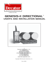
Figure 6 Bumper Shape Requirements
4 Certified Product & Warnings
Please take attention that changes or modification not expressly approved by the party responsible for
compliance could void the user’s authority to operate the equipment.
This device complies with Part 15 of the FCC Rules. Operation is subject to the following two
conditions:
(1) This device may not cause harmful interference, and
(2) This device must accept any interference received, including interference that may cause
undesired operation.
This device complies with Industry Canada licence-exempt RSS standard(s). Operation is subject to
the following two conditions:
(1) this device may not cause interference, and
(2) this device must accept any interference, including interference that may cause undesired
operation of the device.
Le présent appareil est conforme aux CNR d'Industrie Canada applicables aux appareils radioexempts
de licence. L'exploitation est autorisée aux deux conditions suivantes :
(1) l'appareil ne doit pas produire de brouillage, et
(2) l'utilisateur de l'appareil doit accepter tout brouillage radioélectrique subi, même si le brouillage est
susceptible d'en compromettre le fonctionnement.
This equipment complies with FCC/IC RSS-102 radiation exposure limits set forth for an
uncontrolled environment. This equipment should be installed and operated with minimum distance
20cm between the radiator & your body.
ce matériel est conforme aux limites de dose d'exposition aux rayonnements, FCC / CNR-102
énoncée dans un autre environnement.cette eqipment devrait être installé et exploité avec distance
minimale de 20 entre le radiateur et votre corps.
§ 95.393 Instructions and warnings.
(1) Instructions concerning all controls, adjustments and switches that may be operated or adjusted
without resulting in a violation of FCC rules;
(2) Warnings concerning any adjustment that could result in a violation of FCC rules or that is
recommended to be performed only by or under the immediate supervision and responsibility of a
person certified as technically qualified to perform transmitter maintenance and repair duties in the
relevant radio service by an organization or committee representative of users of that service;
(3) Warnings concerning the replacement of any transmitter component (crystal, semiconductor, etc.)
that could result in a violation of FCC rules; and
(4) For a transmitter that can only be operated with an FCC license, warnings concerning compliance
with applicable licensing requirements and information concerning license application procedures.
  • Page 1 1
  • Page 2 2
  • Page 3 3
  • Page 4 4
  • Page 5 5
  • Page 6 6
  • Page 7 7
  • Page 8 8
  • Page 9 9
  • Page 10 10

Nova 7GB-A 77GHz Millimeter-Wave Radar User manual

Type
User manual
This manual is also suitable for

Nova 7GB-A 77GHz Millimeter-Wave Radar is a device that complements a vehicle's rearview mirror by detecting the driving environment and issuing warnings to the driver if a lane change is not recommended. The radar can be installed inside the rear bumper, with specific requirements for height, angle, and error to ensure accurate detection. It operates at 77GHz and has a range of up to 0.8m, with a beam that covers the direction without any metal parts or painted bumpers.

Ask a question and I''ll find the answer in the document

Finding information in a document is now easier with AI