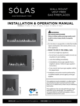
Solas SL-16N User manual

Category
Fireplaces
Type
User manual

The Solas SL-16N is a powerful and versatile fireplace that offers a range of features to enhance your home's ambiance and comfort. With its sleek design and compact size, it fits seamlessly into any room, providing warmth and elegance. The SL-16N boasts efficient heating capabilities, distributing heat evenly throughout your space, making it an ideal choice for chilly evenings or as a supplemental heat source. Its realistic flame effect creates a captivating atmosphere, adding a touch of charm and coziness to your living area.

The Solas SL-16N is a powerful and versatile fireplace that offers a range of features to enhance your home's ambiance and comfort. With its sleek design and compact size, it fits seamlessly into any room, providing warmth and elegance. The SL-16N boasts efficient heating capabilities, distributing heat evenly throughout your space, making it an ideal choice for chilly evenings or as a supplemental heat source. Its realistic flame effect creates a captivating atmosphere, adding a touch of charm and coziness to your living area.

THIS POWER VENT KIT IS ONLY FOR USE WITH THE FOLLOWING SÓLAS MODELS:
SL-16N, SL-16P, SL-26N, SL-26P, ST-46N, ST-46P, FS-16N-RV, FS-16P-RV, FS-16N-TV, FS-16P-TV, BI-38N-C, BI-38P-C,
BI-38N-T, BI-38P-T, BI-48-SSL, BI-48-SSR, BI-48-ST, BI-60-SSL, BI-60-SSR, BI-60-ST, BI-72-SSL, BI-72-SSR, BI-72-ST
SELF-CALIBRATING
POWER VENT CONTROL
AND TERMINATION KIT
Ce manual est disponsible en Francais sur demande.
SCPV-900C SHOWN
SÓLAS STRONGLY SUGGESTS THAT YOU READ THIS
MANUAL THOROUGHLY BEFORE BEGINNING THE
INSTALLATION OF THE SÓLAS POWER VENT KIT. THIS
SPECIFIC PRODUCT HAS ITS OWN UNIQUE SET-UP AND
INSTALLATION REQUIREMENTS THAT MUST BE
FOLLOWED EXACTLY. PLAN YOUR INSTALLATION IN
ADVANCE BY CAREFULLY RE-VIEWING ALL THE
INFORMATION CONTAINED IN THIS MANUAL.
WARNING: ALL INSTALLATION, SERVICING, AND
TROUBLESHOOTING MUST BE PERFORMED BY A
QUALIFIED GAS TECHNICIAN.
2
TABLE OF CONTENTS
SÓLAS Power Vent Components 3
SÓLAS Power Vent Terminations 4
Flush-mount Termination specifications 6
Surface-mount Termination specifications 7
Power Vent Clearances 8
Venting Configurations 9
Flush Mount (side wall) Installation 10
Surface Mount (side wall) Installation 11
Vertical (thru the roof) Installation 12
Installation Instructions 14
Electrical Instructions 16
Calibration and Operation 17
Troubleshooting 20
Replacement Parts List 22
Warranty Information 23
WARNING:
This installation manual covers the functional
requirements for optimal performance of your
fireplace with power vent installation, consult with a
professional architect, civil engineer, or home
builder regarding the building code, aesthetic and
functional finishing requirements of the home.
NOTE:
LAS advises that the appliance installation should
be calibrated, tested, and the fireplace burned to
ensure optimal performance and desired flame
aesthetics BEFORE the vent system or fireplace are
enclosed and walls or ceilings are finished.
3
SÓLAS POWER VENT COMPONENTS
SCPV-900C - Self-Calibrating Power Vent Control
Module, required for all power vent installations.
SCPV-905PS - Self-Calibrating Power Vent Pressure
Switch, required for all power vent installations. Only
use the pressure switch certified by SÓLAS with the
SÓLAS Self-Calibrating Power Vent Control. Connect
to pressure port using the 12ft length of ¼” ID silicon
tubing (not shown) supplied with the Self-Calibrating
Powervent control kit.
SCPV-914GS - Self-Calibrating Power Vent Gas
Solenoid, required for all power vent installations.
Only gas solenoids certified for use by SÓLAS are to be
used with the SÓLAS Self-Calibrating Power Vent
Control.
SCPV-TWH-XX - Self-Calibrating Power Vent
termination wire harness, required for all power vent
installations. The termination wire harness is available
in 25, 50, 100, and 150 lengths.
Harness Part #
SCPV-TWH-25
SCPV-TWH-50
SCPV-TWH-100
SCPV-TWH-150
4
SÓLAS POWER VENT TERMINATIONS
SCPV-946DVA – Self-Calibrating Power Vent Pressure
Port Vent Adapter, required with terminations SCPV-
130-FLUSH, SCPV-130-SURFACE, and SCPV-130-
VERTICAL.
NOTE: This adapter, based on M&G Duravent’s 46DVA-
06 directvent pipe, should be installed immediately on
the starter collar of the fireplace. For SÓLAS fireplaces
requiring a 45° elbow immediately following the
starter, this adapter should be installed immediately
following the 45° elbow.
SCPV-130-FLUSH – Self-Calibrating Power Vent
Flush-Mount Termination, for use with vent runs over
10 feet in length, regardless of the number of elbows
in the vent configuration. This termination requires
the use of SCPV-946DVA - Self-Calibrating Power Vent
Pressure Port Vent Adapter.
SCPV-130-SURFACE – Self-Calibrating Power Vent
Surface-Mount Termination, for use with vent runs
over 10 feet in length, regardless of the number of
elbows in the vent configuration. This termination
requires the use of SCPV-946DVA - Self-Calibrating
Power Vent Pressure Port Vent Adapter.
SCPV-10-SRSM – Self-Calibrating Power Vent
Surface-Mount Termination, for use with vent runs
under 10 feet in length, regardless of the number of
elbows in the vent configuration. This termination is
Not to be used with SCPV-946DVA - Self-Calibrating
Power Vent Pressure Port Vent Adapter.
NOTE: This termination can be differentiated from
SCPV-130-SURFACE by the addition of the pressure
port on the rear top-left corner of the termination.
PRESSURE PORT
5
SÓLAS POWER VENT TERMINATIONS
SCPV-130-VERTICAL – Self-Calibrating Power Vent
Vertical Termination, for use with vertically
terminating vent runs only. This termination requires
the use of SCPV-946DVA - Self-Calibrating Power Vent
Pressure Port Vent Adapter.
The SOLAS Self-Calibrating Power vent kit can only be used in conjunction with the SÓLAS Contemporary
Fire products listed below. This installation must conform with local codes, or, in the absence of local
codes, with the National Fuel Gas Code, ANSIZ2223.1/NFPA 54, or the Natural Gas and Propane Installation
Code, CSA B149.1.
THIS POWER VENT KIT IS ONLY FOR USE WITH THE FOLLOWING SÓLAS MODELS:
SL-16N, SL-16P, SL-26N, SL-26P, ST-46N, ST-46P, FS-16N-RV, FS-16P-RV, FS-16N-TV, FS-16P-TV, BI-38N-C, BI-38P-C,
BI-38N-T, BI-38P-T, BI-48-SSL, BI-48-SSR, BI-48-ST, BI-60-SSL, BI-60-SSR, BI-60-ST, BI-72-SSL, BI-72-SSR, BI-72-ST
This kit uses either M&G Duravent direct vent pipe, Secure Vent direct vent pipe, or Selkirk Direct-
temp vent pipe with a 4” inner pipe and a 6-5/8” outer pipe.
Vertical installations must use the SCPV-130-VERTICAL termination. The vertical termination can only
be installed on flat surfaces; sloped surfaces require construction of a chase which provides the minimum
interior square opening of 11.9”x12.9” (302mm x 328mm) for the venting and wiring to pass through. Flat
roofs may require a chase depending on local codes and roof construction. (If in doubt check with your
local inspector)
ALWAYS MAINTAIN THE REQUIRED 1.5” (38mm) CLEARANCE TO COMBUSTIBLES AND ELECTRICAL
WIRING AROUND VENT PIPE.
The location of the Power Vent termination must be in accordance with the clearances outlined in the
venting section of this manual on page 8.
For replacement parts, refer to page 22. Replacement parts can be ordered through your authorized
SÓLAS dealer.
6
FLUSH-MOUNT TERMINATION SPECIFICATIONS
SCPV-130-FLUSH – Self-Calibrating Flush-Mount Power Vent Dimensions:
SCPV-130-Flush – Self-Calibrating Flush-Mount Power Vent Cavity Dimensions:
NAILING FLANGE
FLUE OUTLET
7
SURFACE-MOUNT TERMINATION SPECIFICATIONS
SCPV-10-SRSM & SCPV-130-SURFACE – Self-Calibrating Surface-Mount Power Vent Dimensions:
SCPV-10-SRSM & SCPV-130-SURFACE – Self-Calibrating Surface-Mount* Power Vent Cavity Dimensions:
*These dimensions apply to SCPV-130-SURFACE and SCPV-10-SRSM, see page 12 for SCPV-130-VERTICAL
FLUE OUTLET
NAILING FLANGE
PRESSURE PORT
8
POWER VENT CLEARANCES
Figure #1
A. clearances above grade, veranda, porch, deck, or balcony [*12 inches (30 cm) minimum]
B. clearance to window or door that may be opened [* 12 inches (30 cm) minimum]
C. clearance to permanently closed window [minimum 12 inches (30 cm) recommended to prevent condensation on
window]
D. vertical clearance to ventilated soffit located above the terminal within a horizontal distance of 2 feet (60 cm) from
the edge of the terminal [12 inches (30 cm) minimum]
E. clearance to unventilated soffit [12 inches (30 cm) minimum]
F. clearance to outside corner [6 inches (15 cm) minimum]
G. clearance to inside corner [6 inches (15 cm) minimum]
H. * not to be installed above a meter/regulator assembly within 3 feet (90 cm) horizontally from the center-line of the
regulator
I. clearance to service regulator vent outlet [* 6 feet (1.8 m) minimum]
J. clearance to non-mechanical air supply inlet to building or the combustion air inlet to any other appliance [* 12
inches (30 cm) minimum]
K. clearance to a mechanical air supply inlet [* 6 feet (1.8 m) minimum]
L. ^ clearance above paved side-walk or a paved driveway located on public property [* 7 feet (2.1 m) minimum]
M. clearance under veranda, porch, deck, or balcony [12 inches (30 cm) minimum**]
^ a vent shall not terminate directly above a side-walk or paved driveway which is located between two single family
dwellings and serves both dwellings*
** only permitted if veranda, porch, deck, or balcony is fully open on a minimum of 2 sides beneath the floor*
* as specified in CGA B149 Installation Codes, Note: local Codes or Regulation may require different clearances
* for U.S.A. Installations follow the current National Fuel Gas Code, NSI Z223.1
9
VENTING CONFIGURATIONS
Figure #2
WARNING:
A minimum clearance to combustibles and electrical wiring of 1.5” (38mm) is required around the vent
pipe at all times. Failure to maintain this clearance may result in property damage, injury, or death.
NOTE: The vent pipe must engage the power vent termination by at least 1.5” (38mm) to ensure the
vent system is intact. Seal the joint with foil tape and self-tapping sheet metal screws (included).
Figure #3
NOTE: IT IS PERMISSIBLE TO VENT HORIZONTALLY, DIRECTLY OFF OF THE UNIT, NO VERTICAL RISE IS
REQUIRED WHEN EQUIPPED WITH A POWER VENT AS SHOWN IN FIGURE #3.
Maximum venting 130ft
including (8) 90° elbows.
Vertical terminations
require the use of
SCPV-130-VERTICAL
Max 6ft downward
venting permitted
10
FLUSH MOUNT (SIDE WALL) INSTALLATION
NOTE: Locate the power vent termination following the clearance to combustible table, venting
configuration diagram (Fig. #2 & 3), and terminal location diagram (Fig. #1).
NOTE: The following instructions are for use SCPV-130-FLUSH only.
1. SCPV-130-FLUSH is designed to fit on center in between standard exterior 2x6 exterior framing. The
opening required in the framing and exterior sheathing is 14.50” (368mm) wide by 14.50” (368mm)
tall as shown in the image (right).
2. The power vent termination is secured to the sidewall by the left, right, top and bottom nailing
flanges shown on page 6.
3. The power vent termination requires a 1/8” clearance to the siding to permit servicing of the
blower motor. With this clearance requirement in mind, the opening required in the siding is 15.63”
(397mm) wide by 13.13” (333.5mm) tall.
Required opening in framing &
sheathing
Power Vent installed in required
opening in framing & sheathing
Required opening in finished siding
Power Vent install with finished siding
11
SURFACE MOUNT (SIDE WALL) INSTALLATION
NOTE: Locate the power vent termination following the clearance to combustible table, venting
configuration diagram (Fig. #2 & 3), and terminal location diagram (Fig. #1).
NOTE: The following instructions are for use SCPV-130-SURFACE & SCPV-10-SRSM only.
1. SCPV-130-SURFACE and SCPV-10-SRSM are designed to fit on center in between standard exterior
2x6 exterior framing. The opening required in the framing and exterior sheathing is 14.50” (368mm)
wide by 10.00” (254mm) tall as shown in the image (right).
2. The power vent termination is secured to the sidewall by the left and right nailing flanges shown on
page 7.
3. The power vent termination requires a 1/8” clearance to the siding to permit servicing of the
blower motor. The opening required in the siding is 11.50” (292mm) wide by 10.25” (260mm) tall.
Required opening in framing & sheathing
Power Vent installed in required
opening in framing & sheathing
Required opening in finished siding
Power Vent install with finished siding
12
VERTICAL (THRU THE ROOF) INSTALLATION
NOTE: SCPV-130-VERTICAL shown, vertical terminating installations MUST use SCPV-130-VERTICAL
only.
NOTE: LOCAL CODES OR REGULATIONS MAY REQUIRE INCREASED CLEARANCES.
For flat roof installations, check local codes for dimensional requirements for the site fabricated chase.
WARNING: This installation manual covers the functional requirements for optimal performance of
your fireplace with power vent installation, consult with a professional architect, civil engineer, or
home builder regarding the building code, aesthetic and functional finishing requirements of the home.
Final installation height: 21.0” (533mm)
Site fabricated chase minimum height: 14.5” (368mm) Figure 5
13
VERTICAL (THRU THE ROOF) INSTALLATION
NOTE: The site fabricated chase must be a minimum of 14.5” (368mm) tall, additional height may be
required to prevent obstruction of the exhaust outlet by snow accumulation.
NOTE: Orientate the power vent so the exhaust outlet is facing away from the home, roof, or any
potential obstructions. The chase may require additional height to avoid obstructions or nearby
features.
NOTE: when fabricating the chase, be sure that combustibles and electrical wiring are a minimum of
1.5” (38mm) from the vent pipe at all times.
1. The inside dimensions of the site fabricated
chase should be 12.9” (328mm) long by 11.9”
(302mm) wide. The exhaust outlet is on the
12.9” (328mm) long side of the chase.
2. Exterior dimensions of the site fabricated
chase should be 18.9” (480mm) long by
(455mm) wide. The exhaust outlet is on the
18.9” (480mm) long side of the chase.
3. The vent pipe should be installed so that it
sits 6” (152mm) below the top surface of the
site fabricated chase. This will ensure that
the power vent termination engages by at
least 1.5” (38mm).
4. When running SCPV-TWH-XX - Self-
Calibrating Power Vent termination wire
harness through the chase to meet the
termination, be sure the harness is a
minimum of 1.5” (38mm) from the vent pipe
at all times. Secure the wire harness as
necessary to be sure this distance is
maintained.
5. Apply a silicone sealant to the mating surface
of the site fabricated chase as the
termination is installed. Secure the
termination with the (8pcs) included #8 x ¾
pan head wood screws.
14
INSTALLATION INSTRUCTIONS
The above image shows the power vent control,
part #SCPV-900C
The image above shows the pressure switch
(SCPV-905PS) used with the Self-Calibrating
Power Vent. The black port should be left open
to the atmosphere; the grey port should be
connected to the vent pressure tap using the
included silicone tubing. The pressure switch
requires a negative pressure of 0.05” W.C. to
confirm the power vent is running and permit
the gas solenoid to open allowing the main
burner to ignite.
There are 4 wire harnesses in addition to the
power cord along the top edge of the Self-
Calibrating Power Vent Control. The lower
“Termination Harness Plug” is for the Termination
Wire Harness which carries power to the power
vent and restrictor position signals back to the
control board. (see below).
Connect the black 10-pin bladed connector of the
Termination Wire Harness (SCPV-TWH-XX) to the
Termination Harness Plug, the White 10-pin
header will plug into the Power Vent Termination.
As is required for all combustible materials, this
Wire Harness must remain at least 1.50” (38mm)
away from the vent pipe at all times.
TO PRESSURE SWITCH
GV60 AUX
RED TC
TO GAS SOLENOID
POWER CORD
TERMINATION
HARNESS PLUG
LOCATION
This side of the
harness plugs into
the power vent
control
This side of the
harness plugs into
the power vent
termination
15
INSTALLATION INSTRUCTIONS
FOR VENT RUNS OVER 10FT IN LENGTH:
FOR VENT RUNS UNDER 10FT IN LENGTH:
Install the Self-Calibrating Power Vent Pressure
Port Adapter (SCPV-946DVA) immediately
following the appliance starter collar (or 45 elbow
off the unit when required). Connect the silicone
tube from the pressure tap on the vent adapter to
the light grey port on the control using the
pressure switch tubing provided with the Self-
Calibrating Power Vent Pressure Switch (SCPV-
905GS). 12ft of tubing is supplied with the
Powervent control, (SCPV-900C). Only use the
length of tubing that is necessary for your
installation, trim to length. Tape all seams in the
venting system using Aluminum Foil HVAC Tape.
For vent runs that are under 10 feet in length
excluding elbows the Self-Calibrating Power Vent
Pressure Port Adapter (SCPV-946DVA) WILL NOT
BE USED. Installations which use less than 10 feet
of vent pipe excluding elbows will be terminated
using SCPV-10-SRSM, Self-Calibrating Power Vent
Surface-Mount Termination. Once the fireplace is
in position, vent run and termination are installed,
connect the silicone pressure tubing from the
pressure switch near the power vent control to the
pressure port on the back of the power vent
termination. 12ft of tubing is supplied with the
Powervent control, (SCPV-900C). Only use the
length of tubing that is necessary for your
installation, trim to length. SCPV-10-SRSM is the
only termination which includes this port.
16
ELECTRICAL INSTRUCTIONS
NOTE: Once the electrical wiring has been completed, test the system to be sure its performance is as
desired before the finishing work is completed and the fireplace is enclosed within the wall.
WARNING
All electrical shall be completed by a licensed Electrician and must conform with local building code.
Improper installation may result in property damage, injury, or loss of life.
Caution: Label all wires prior to disconnection when servicing the controls. Wiring errors can cause
improper and dangerous operation. Verify proper operation after servicing.
TERMINATION HARNESS SCPV-TWH-XX
17
CALIBRATION AND OPERATION
WARNING: BEFORE SERVICING THE POWERVENT CONTROL, DISCONNECTING OR RECONNECTING
ANY WIRE HARNESS, DISCONNECT POWER TO THE APPLIANCE.
WARNING: ALL INSTALLATION, SERVICING, AND TROUBLESHOOTING MUST BE PERFORMED BY A
QUALIFIED GAS TECHNICIAN.
NOTE: ANY TIME POWER IS APPLIED TO THE POWER VENT CONTROL, THE CONTROL WILL BEGIN A 60
SECOND PURGE CYCLE, DURING THIS PURGE CYCLE THE CALIBRATION SEQUENCE CANNOT BE
INITIATED. DURING THE PURGE CYCLE, THE “OPERATION STATUS LED” WILL BE BLUE.
NOTE: ANY TIME THE RESET BUTTON IS PRESSED ON THE POWER VENT CONTROL, THE CONTROL WILL
BEGIN A 60 SECOND PURGE CYCLE, DURING THIS PURGE CYCLE THE CALIBRATION SEQUENCE CANNOT
BE INITIATED. DURING THE PURGE CYCLE, THE “OPERATION STATUS LED” WILL BE BLUE.
NOTE: In the event of a power loss during normal operation, the power vent and fireplace will shut
down. When power is restored the unit will be locked out. To relight the unit, press the off button on
the remote, listen for a single beep from the GV60 control. Once a single beep is heard, the fireplace can
be relit following the instructions on the lighting label of the appliance.
ON/OFF SWITCH
CALIBRATE BUTTON
RESET BUTTON
OPERATION STATUS LED
CALIBRATION STATUS LED
POWER LED
PRESSURE LED
SCPV-12218-XX
TERMINATION
HARNESS PLUG
LOCATION
18
CALIBRATION AND OPERATION
Calibration Sequence
When the fireplace, venting, and Power vent
termination have been installed, the calibration
sequence can be initiated prior to test burning the
fireplace for the first time.
1. Connect power to the power vent control, turn
on the on/off switch. A 60 second purge cycle
will begin; calibration cannot begin during this
time. During the purge cycle, the “Operation
Status LED” will be blue. Once the purge cycle
has completed, the LED will turn off.
2. Press the Calibration” button to begin the
calibration sequence. The “Calibration Status
LED” will turn blue as the calibration sequence
begins.
NOTE: It should only be necessary to complete the
calibration sequence when the appliance is first installed,
however, if a service technician wants to conduct a
calibration sequence at any time in the product’s life this
is ok.
3. Without any user intervention, the calibration
sequence is as follows:
The restrictor contained within the power vent
termination will close. Once the restrictor is closed, the
power vent blower will start. When the power vent
blower has reached is operating RPM, the restrictor will
begin to open. Once the appropriate pressure is reached
within the vent system, the “Pressure LED” will illuminate
green and the restrictor will lock in the correct position.
4. Upon a successful calibration, the “Calibration
Status LED” will turn green.
5. The fireplace is now ready to operate.
NOTE: If power is disconnected from the appliance after the
calibration sequence has been successfully completed, the
“Calibration Status LED” will no longer be illuminated green,
however, the restrictor will not have moved and the power
vent system will still operate normally.
ON/OFF SWITCH
OPERATION STATUS LED
CALIBRATION STATUS LED
CALIBRATE BUTTON
PRESSURE LED
CALIBRATION STATUS LED
19
CALIBRATION AND OPERATION
Normal Operation
The SÓLAS Self-Calibrating Power Vent control is designed to
integrate seamlessly with the Maxitrol GV60 control system
used in all SÓLAS Direct-Vent Gas Fireplaces. No user
intervention is required for the power vent control to operate
during normal operation of the appliance, the following is to
aid in understanding typical operation characteristics.
1. Light the fireplace using the SÓLAS fireplace remote,
refer to the lighting label or lighting instructions in the
product manual.
2. As the lighting sequence begins, the power vent will
turn on.
3. When the pressure switch closes the “pressure LED
will turn on, the “Operation Status LED” will turn
green.
4. When the “Operation Status LED” turns green,
indicating normal operation, the gas solenoid (SCPV-
914GS) will open, allowing the main burner to ignite.
5. The power vent blower will remain on until the unit is
turned to standby (pilot only) or shut down
completely.
6. When the unit is turned to standby (pilot only) or shut
down completely, the “Operation Status LED” will turn
blue, and a 60 second purge cycle will begin. Once the
purge cycle is complete, the blower will remain off
until the main burner is lit again.
NOTE: ANY TIME THE RESET BUTTON IS PRESSED ON THE
POWER VENT CONTROL, THE CONTROL WILL BEGIN A 60
SECOND PURGE CYCLE, DURING THIS PURGE CYCLE THE
CALIBRATION SEQUENCE CANNOT BE INITIATED. DURING
THE PURGE CYCLE, THE “OPERATION STATUS LED” WILL BE
BLUE.
NOTE: During thermostatic mode, any time the GV60
control turns off the main burner, the power vent will enter
a purge cycle and then turn off. The next time the GV60
control initiates a call for heat, the power vent will start as
described above, permitting the main burner to ignite.
NOTE: If power is disconnected from the appliance after the
calibration sequence has been successfully completed, the
“Calibration Status LED” will no longer be illuminated
green, however, the restrictor will not have moved and the
power vent system will still operate normally.
NOTE: In the event of a power loss during normal
operation, the power vent and fireplace will shut down.
When power is restored the unit will be locked out. To
relight the unit, press the off button on the remote, listen
for a single beep from the GV60 control. Once a single beep
is heard, the fireplace can be relit following the instructions
found on the lighting label of the appliance.
WARNING: BEFORE SERVICING THE
POWERVENT CONTROL, DISCONNECTING OR
RECONNECTING ANY WIRE HARNESS,
DISCONNECT POWER TO THE APPLIANCE.
WARNING: ALL INSTALLATION, SERVICING, AND
TROUBLESHOOTING MUST BE PERFORMED BY
A QUALIFIED GAS TECHNICIAN.
OPERATION STATUS LED
PRESSURE LED
OPERATION STATUS LED
  • Page 1 1
  • Page 2 2
  • Page 3 3
  • Page 4 4
  • Page 5 5
  • Page 6 6
  • Page 7 7
  • Page 8 8
  • Page 9 9
  • Page 10 10
  • Page 11 11
  • Page 12 12
  • Page 13 13
  • Page 14 14
  • Page 15 15
  • Page 16 16
  • Page 17 17
  • Page 18 18
  • Page 19 19
  • Page 20 20
  • Page 21 21
  • Page 22 22
  • Page 23 23
  • Page 24 24
  • Page 25 25

Solas SL-16N User manual

Category
Fireplaces
Type
User manual

The Solas SL-16N is a powerful and versatile fireplace that offers a range of features to enhance your home's ambiance and comfort. With its sleek design and compact size, it fits seamlessly into any room, providing warmth and elegance. The SL-16N boasts efficient heating capabilities, distributing heat evenly throughout your space, making it an ideal choice for chilly evenings or as a supplemental heat source. Its realistic flame effect creates a captivating atmosphere, adding a touch of charm and coziness to your living area.

Ask a question and I''ll find the answer in the document

Finding information in a document is now easier with AI