6
2. Use a lever to remove the terminal block from
the switch.
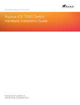
Figure 13
3. Using a flat head screwdriver, loosen the
connections in the terminal block by un-screwing
the terminal connections that you wish to use.
4. Insert the wires into the terminal connections
and use the screwdriver to tighten the screws
to secure the wires.
Figure 14
5. Re-insert the terminal block into the terminal
block socket on the DIS-200G.
Management Options
The DIS-200G can be managed by using the Web
User Interface (Web UI), D-Link Network Assistant
(DNA), console port, Telnet, or Simple Network
Management Protocol (SNMP) management
interfaces.
If you wish to manage a single D-Link switch, the
Web UI may be the best option. Each switch must
be assigned its own IP address, which is used for
communication with the management PC. However,
if you wish to manage multiple D-Link switches, DNA
may be the best option. You do not need to change
the IP address of your PC and it makes the initial set
up of multiple switches easy.
Please refer to the following installation instructions
to get started with the Web UI, DNA, console port,
Telnet, and SNMP management interfaces.
Web User Interface
Once the switch has been successfully installed, you
can begin conguration, monitor the LED panel,
and display graphical statistics using a web browser.
Supported browsers include: Microsoft® Internet
Explorer, Firefox, Chrome, and Safari.
You need the following equipment to access the Web
UI of your device:
• A PC with an RJ-45 Ethernet connection
• A standard Ethernet cable
1. Connect the Ethernet cable to any of the ports
on the switch’s front panel and to the Ethernet
port on the PC.
2. Congure the PC’s IP address to be in the same
network segment as the switch. The switch’s
default IP address is 10.90.90.90, with subnet
mask 255.0.0.0. For example, to connect to the
switch using the default settings, your PC should
have an IP address in the range: 10.0-255.0-255.0-
254 and a subnet mask of 255.0.0.0.
3. Open a web browser and enter http://10.90.90.90/
in the address box. Note: The Web UI can also be
accessed through DNA, by clicking the switch’s
IP in the device list.
4. Log in to the switch. To do this, enter admin as
the default user name and password and click OK.
D-Link Network Assistant (depend-
ing on the purchased model)
D-Link Network Assistant (DNA) is a program that is
used to discover switches which are in the same Layer
2 network segment as your PC. Please refer to the
following steps to get started with DNA.
1. Go to http://tools.dlink.com/intro/dna/
2. Select “Free Download” button to open DNA
download page for download
Note: for Managed Switch, users need to enable
D-Link Discovery Protocol (DDP) and create a user
name and password to be able to log in to DNA.”
Console
To connect to the switch’s console, use the supplied
cable to connect to the switch’s console port. This
cable is a RS-232 serial to RJ-45 connector cable