Page is loading ...

EnglishFrançaisItalianoHrvatskiDeutschEspañol
EnglishFrançaisItalianoHrvatskiDeutschEspañol
2 3
www.williamsjettenders.com www.williamsjettenders.com
32
Español Deutsch Hrvatski Italiano Français English
English
4–23
Owner’s Handbook
Owner’s Handbook
English
4–21
Français
22–39
Italiano
40–57
Hrvatski
58–75
Deutsch
76–93
Español
94 –111
williamsjettenders.com

English
www.williamsjettenders.com www.williamsjettenders.com
5
English
4
Thank You for Choosing a
Williams Dieseljet
This owner’s handbook has been compiled to help you operate your Dieseljet with safety and
pleasure. It contains details of the boat and equipment tted, together with information on its
operation and maintenance. Please read it carefully, along with the Yanmar Engine manual,
and familiarise yourself with the boat before using it.
The Williams Dieseljet uses water jet propulsion. If this is your rst boat or you are changing
to a type of boat you are not familiar with, for your own safety, please ensure that you obtain
handling and operating experience before assuming command of the boat. Your dealer,
national sailing federation or yacht club will be pleased to advise you of sea schools, or
competent instructors.
To take advantage of the Yanmar Engine Warranty, please remember to register your engine
online at www.yanmarmarine.com.
The Dieseljet range are high performance boats. Williams recommends a minimum
standard of RYA level 2 or ICC (International certificate of competency) is attained by
the operator prior to taking control of this boat. This manual assumes the operator has
acquired this standard of qualification and possesses knowledge of basic seamanship.
Please keep this handbook in a secure place and hand it to the new
owner if you sell the boat.
Hull Identification Number (HIN):
Safety
Williams Performance Tenders consider the safety of our customers of great importance. We
recommend people using our products exercise care and common sense, and comply with
the safety information within the Owner’s Handbook.
Always obey the safety labels tted to the tender and replace should they become unreadable.
Be aware of local laws and restrictions and never use whilst under the inuence of alcohol or
any substance which may aect your judgement.
This symbol appears on a number of labels tted to the Tender.
The symbol draws your attention to the message and refers you to the Owner’s
Handbook.
This safety alert symbol appears throughout the Owner’s Handbook and appears on
various labels tted to the tender. It means attention, be alert, your safety is involved!
Please read and abide by the message that follows the safety alert symbol.
DANGER
Indicates a hazardous situation which, if not avoided, will result in death or serious injury.
WARNING
Indicates a hazardous situation which, if not avoided, could result in death or serious injury.
CAUTION
Indicates a hazardous situation which, if not avoided, could result in minor or moderate injury.
Classication
Category C – “inshore”: Craft designed for voyages in coastal waters, large bays, estuaries,
lakes and rivers, where conditions up to and including wind force 6 and signicant wave
heights up to and including 2m may be experienced. These boats comply with ISO 6185-3.
The Hull Identication Number is located above jet nozzle on starboard side below platform
step: record it in the box opposite. The CE plate is located in the starboard footwell. The CE
plate is the certication to European Directive 94/25/CE.
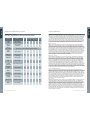
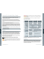
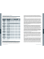
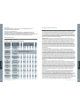
Engine Specications
Dieseljet 445 & 505 Dieseljet 565 Dieseljet 625
Yanmar engine type
4JH4-HTE (110hp) 4BY3 (150hp, 180hp) 6BY3 (180hp, 260hp)
Maximum output
(Crankshaft)
80.9 kW (110 mhp) /
3200 rpm
110 kW (150 mhp) /
4000 rpm
162 kW (220 mhp) /
4000 rpm
Configuration
Water cooled, turbocharged, direct injection diesel
Displacement
1.995 L (122 cu in) 2.993 L (183 cu in)
Cylinders
4 cylinders 6 cylinders
Cooling system
Fresh water cooling by centrifugal water pump and
rubber impeller sea water pump
U.S. Specification – Dieseljet 445 & 505: Yanmar 4JH4-HTE1: 100hp, 2950rpm
Oil grade
15W40 0W40 – 10W30
API categories CD or higher
Coolant
Texaco Long Life
Coolant (LLC)
or Havoline
Extended life
antifreeze/coolant
30%-60%
Glysantin G48-24 engine coolant
Fuel
Diesel

EnglishFrançaisItalianoHrvatskiDeutschEspañol
6 7
www.williamsjettenders.com www.williamsjettenders.com
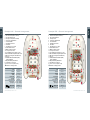
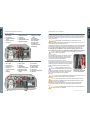
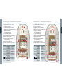
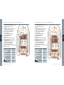
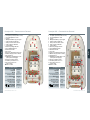
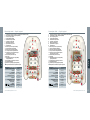
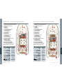
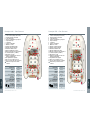
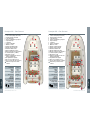
Dieseljet 505 – General Arrangement
1 Port and Starboard navigation light socket
2 Anchor locker (under cushion)
3 Shower fill and head
4 Storage locker
5 Passenger grab handles
6 Footwell drains
7 Boarding post bases
8 Fuel filler
9 Throttle/reverse control
10 Tube inflation valves
11 Main electrical isolator
12 Over pressure valves
13 12v auxiliary power/charge socket
14 All-round white navigation light socket
15 Mooring cleat (port and starboard)
16 Ski eye
17 Hull Identification Number (HIN)
(under platform)
18 Engine flushing attachment
19 Tail shaft access hatch
20 Seacock access (under seat)
@
Indicates seating position
General specifications
LOA
5.05 m
Beam
2.02 m
Height
1.1 m
Draft
0.27 – 0.42 m
Dry weight
860 kg
Seating
8
Fuel capacity
85 litres
Max speed
(US spec)
40 mph / 64 kph
(37 mph / 60 kph)
Max load
725 kg
Design Category (CE)
C
English
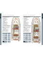
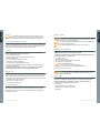
Dieseljet 445 – General Arrangement
1 Port and Starboard navigation light socket
2 Anchor locker (under cushion)
3 Shower fill and head
4 Storage locker (under cushion)
5 Passenger grab handles
6 Footwell drains
7 Boarding post bases
8 Fuel filler
9 Throttle/reverse control
10 Tube inflation valves
11 Main electrical isolator
12 Over pressure valves
13 12v auxiliary power/charge socket
14 All-round white navigation light socket
15 Mooring cleat (port and starboard)
16 Ski eye
17 Hull Identification Number (HIN)
(under platform)
18 Engine flushing attachment
19 Tail shaft access hatch
20 Seacock access (under seat)
@
Indicates seating position
General specifications
LOA
4.45 m
Beam
2.02 m
Height
1.1 m
Draft
0.27 – 0.42 m
Dry weight
825 kg
Seating
7
Fuel capacity
80 litres
Max speed
(US spec)
40 mph / 64 kph
(37 mph / 60 kph)
Max load
518 kg
Design Category (CE)
C
English
6
1515
4
4
5
5
6
6
6
6
1
7
9
10
10 10
12
12
8
14
12
17
16
2
3
5
134 11
@
@
@
@
@
@
@ @
18
3
19
20
+
+
1515
4
4
4
5
5
6
6
6
6
1
7
9
10
10 10
10
12
8
14
12
11
17
16
2
3
3
13
13
@
@
@
@
@
@
@
18
19
20

English
8 9
www.williamsjettenders.com www.williamsjettenders.com
English
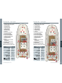
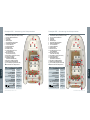
Dieseljet 565 – General Arrangement
1 Port and Starboard navigation light socket
2 Anchor locker (under cushion)
3 Shower fill and head
4 Storage locker
5 Passenger grab handles
6 Footwell drains
7 Boarding post bases
8 Fuel filler
9 Throttle/reverse control
10 Tube inflation valves
11 Main electrical isolator
12 Over pressure valves
13 12v auxiliary power/charge socket
14 All-round white navigation light socket
15 Mooring cleat (port and starboard)
16 Ski eye
17 Hull Identification Number (HIN)
(under platform)
18 Engine flushing attachment
19 Tail shaft access hatch
20 Seacock access (under seat)
@
Indicates seating position
General specifications
LOA
5.70 m
Beam
2.38 m
Height
1.30 m
Draft
0.35 – 0.5 m
Dry weight
1060 kg
Seating
9
Fuel capacity
105 litres
Max speed
150hp
180hp
39 mph / 63 kph
41 mph / 66 kph
Max load
800 kg
Design Category (CE)
C
Dieseljet 625 – General Arrangement
1 Port and Starboard navigation light socket
2 Anchor locker (under cushion)
3 Shower fill and head
4 Storage locker
5 Passenger grab handles
6 Footwell drains
7 Boarding post bases
8 Fuel filler
9 Throttle/reverse control
10 Tube inflation valves
11 Main electrical isolator
12 Over pressure valves
13 12v auxiliary power/charge socket
14 All-round white navigation light socket
15 Mooring cleat (port and starboard)
16 Ski eye
17 Hull Identification Number (HIN)
(under platform)
18 Engine flushing attachment
19 Tail shaft access hatch
20 Seacock access (under seat)
@
Indicates seating position
General specifications
LOA
6.25 m
Beam
2.38 m
Height
1.16 m
Draft
0.35 – 0.5 m
Dry weight
1250 kg
Seating
11
Fuel capacity
150 litres
Max speed
220hp
260hp
41 mph / 66 kph
47 mph / 76 kph
Max load
900 kg
Design Category (CE)
C
5
1515
4 4
4
5
6
6
6
6
1
7
9
10
10
10 10
12
12
12
8
14
114
17
16
19
2
3
3
20
18
13
@
@
@ @
@
@
@
@ @
5
1515
5
5
6
6
6
6
1
7
9
10
10 10
10
12
12
8
14
12
114
17
19
16
2
20
3
3
13
@
@
@
@@
@
@
@
@
4
4
4
@ @
18
5
+ +

English
11
www.williamsjettenders.com www.williamsjettenders.com
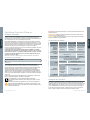
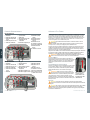
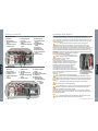
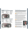
Controls and Instruments Operating Your Tender
This boat uses a water-jet propulsion system and has unique characteristics in steering. The
throttle produces thrust from the jet pump, the directional control is provided by opening the
throttle and turning the wheel in the direction of your turn. High thrust will turn the boat sharply;
low thrust will produce less turning force. There is no rudder, so while underway there is no
steering without thrust.
CAUTION. Maneuverability is severely restricted with reduced throttle or while
decelerating.
After running tender at high speeds it is important to allow engine to idle for a minimum of one
minute before switching o to allow turbo to cool.
If weed or debris gets caught in the jet unit during use cavitation can occur causing a decrease
in forward thrust. If there is any sign of debris or weeds etc. blocking the jet, remove the boat
from the water. Switch o battery isolator and remove all debris from around the jet unit.
DO NOT make repeated attempts to crank a blocked or jammed jet pump as trans-
mission damage may result. In case of difficulty consult your Williams authorized dealer.
WARNING. When moving throttle/reverse control from forward to reverse, delay in
actuator movement will be observed.
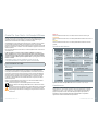
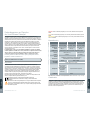
Reverse system
The forward and reverse operation is powered by an electric
actuator located within the engine tray. This item requires
no servicing, but cables should be inspected and greased
according to the periodic maintenance table.
Manual Override of Reverse System
In the event of reverse servo failure, a manual override facility is
in place allowing forward drive of tender. This is by means of a
lockable pin which can be removed from its normal operating
position and secured in the forward bracket, as shown.
Towing
CAUTION. Risk of engine ooding exists. Seacock
must be in CLOSED position when your tender is being
towed and OPEN position when tender is being used. Failure
to observe correct position could result in engine damage.
Refer to General Arrangement for seacock location.
Mooring
CAUTION. Do not leave the Dieseljet moored for extended periods as this may result in
an accumulation of marine growth and a loss of performance.
Beaching
CAUTION. DO NOT operate in less than 0.95m/3ft of water as debris may enter the
jet unit. DO NOT drive Dieseljet onto beach. Stop engine before beaching to prevent
blockage to pump/engine cooling system.
After beaching move boat into deeper water and rock from side to side several times to
remove sand from intake area – failure to do so can cause excessive wear to jet unit.
Trim
CAUTION. Do not overload the boat beyond plated capacity. At all speeds be aware of
trim and keep weight evenly distributed.
Remove securing pin,
manually pull cable forward,
secure in forward bracket
English
10
Dieseljet 445 & 505
1 Rev counter
2 Speedometer
3 Coolant temperature
gauge
4 Oil pressure gauge
5 Fuel gauge
6 Warning light bank
7 VHF radio
8 Safety lanyard
9 Navigation light switch
10 Bilge blower switch
11 Bilge pump override
switch
12 Horn switch
13 Deck light switch
14 Shower switch
15 Throttle control
16 Chart Plotter
17 Engine Stop Button
18 Ignition Key
Dieseljet 565 & 625
1 Rev counter
2 Speedometer
3 Oil pressure gauge
4 Fuel gauge
5 Coolant temperature
gauge
6 Voltmeter
7 Music system
8 VHF radio
9 Safety lanyard
10 Navigation light switch
11 Bilge blower switch
12 Bilge pump override
switch
13 Horn switch
14 Deck light switch
15 Shower switch
16 Throttle control
17 Chart plotter
18 Oil pressure warning light
19 Ignition key
7
15
16
13
14
18
12
11
17
10
9
8
7
3
3
1
1
4
4
2
2
6
6
5
5
9
8
13
15
16
19
14
12
18
11
10
17

English
13
www.williamsjettenders.com www.williamsjettenders.com
English
General
CAUTION. Operate the boat with due care and at a speed appropriate to the sea
conditions. Be aware of local laws and restrictions. Always carry out a visual check of
the boat and its components prior to use. Adhere to the maintenance/service schedule.
New Engine Break-in Period
The way your engine is operated during the rst 50 hours of use will play a very signicant role
in determining its ultimate performance and lifespan. The engine must be operated at suitable
speeds and power settings during the break-in period. Refer to Yanmar engine manuals for
information on running the engine during the rst 50 hours of operation.
Fuelling
As part of its pre-delivery inspection your new Dieseljet has been fully tested and
drained of fuel. When refuelling use only Diesel fuel.
• Do not refuel with engine running.
• Remove Forward seat cushion to expose fuel ller cap (445 only).
• Re-fuel in a ventilated area.
• Do not overll the tank; be careful not to spill fuel.
• Tighten fuel cap securely after re-fuelling.
• Open engine hatch and inspect bilges after re-fuelling.
• The ller cap has an integral breather. Do NOT directly hose around the fuel ller area as
water may enter the fuel tank.
Note: Boats fitted with the Yanmar 4JH4 engine are fitted with a fuel primer/pump.
This may require pumping at first use or when left for extended periods.
Before Use
Tube pressure will uctuate with temperature. Inate tubes in sequence to 250mB/3.6psi, starting
at the rear valves. Failure to observe this will compromise the sea-keeping ability and water tight
integrity of the boat. Ination valves are tted with quarter-turn locks to enable rapid deation.
• Close ination valves; inate tubes evenly, starting at rear/right, rear/left, then forward valves.
• Check bilge for fuel or water contamination.
• Check engine cover latches are secure.
• Check seacock is open before use.
Fire Extinguisher
Inspect system pressure regularly; refer to the extinguisher label for Pressure/Temperature
Table. In some conditions the extinguisher may require resetting; this is done by pressing
the extinguisher reset button found on the extinguisher display unit, refer to Boat System
Arrangement for its location.
Safety Check!
WARNING. ALWAYS attach yourself to the safety lanyard when engine is running. Before
setting o as a precautionary measure always test lanyard for its functionality by pulling
away from its seating – engine should always stop.
WARNING. NEVER operate the boat when bathers are using the boarding ladder, risk of
serious injury exists from reverse deector.
WARNING. NEVER investigate engine bay with engine running or ignition on.
Starting Your Dieseljet
• NEVER run engine if ambient temperature is excessively high or below -16°C (-5°F).
• NEVER attempt to switch off engine using battery isolator.
• Ensure boat is in a depth of at least 0.95m/3ft of water before attempting to start engine.
• Ensure all passengers are correctly seated.
1 Turn on battery isolator.
2 Run bilge blower for 4 minutes.
3 Secure any loose ropes that could get sucked into jet unit.
4 Ensure shift lever is in neutral position.
5 Connect safety lanyard to switch.
WARNING. Personal injury may result if not attached.
6 Test safety lanyard for correct functionality (see Safety Check! above).
Warning Lamps/Alarms
CAUTION. Risk of engine damage. In the event that a warning lamp or buzzer activates
during use, STOP engine immediately, investigate cause and refer to engine manual.
Contact your authorized Williams Dealer.
After Use
To prolong life it is very important to wash entire boat with fresh water after use and prior
to storage, especially the jet pump area. Failure to carry out fresh water washing will
significantly reduce the life of underwater components. Check anodes routinely.
• Flush engine (refer to Flushing Procedure on page 14)
• Wash jet pump
• Check bilge of boat and dry any residual water
• Rinse footwells and upholstery with fresh water
• Isolate battery
12

English
15
www.williamsjettenders.com www.williamsjettenders.com
14
English
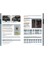
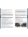
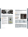
Flushing Procedure
To prolong engine life it is very important to ush engine of salt water after use and prior to
storage. Failure to carry out ushing will signicantly reduce the life of engine components and
may invalidate warranty.
In addition, it is advised to thoroughly wash with fresh water around the jet pump area to
remove all salt deposits after use.
CAUTION. Engine MUST be running
before water is connected. Risk of engine
ooding exists if water remains on after engine is
switched o.
1 Connect a fresh water hose tted with the
male connector supplied with the tender to
the ushing attachment coupling tted to
the tender. Push in outer ring when inserting
ushing connector.
2 Start engine and immediately turn on water
supply.
3 Run engine at idle for approximately 1 minute
to completely ush the open loop cooling
system.
4 Turn o water supply.
5 Allow the engine to run for no longer than 10
seconds to allow water to exit from the cooling
system, then turn o the engine. Remove hose
connector from ushing attachment.
6 Check bilge of boat and dry any residual water.
1
1 Flushing attachment
Oil Level Check
Wait 10 minutes after engine has stopped to accurately check oil level.
• The oil level should be between MIN and MAX on the dipstick.
• Use only correct grade of oil, dependant on engine type (Diesel oil 15W40 or 0W40-10W30,
refer to Engine Specication section and Yanmar Engine Manual.)
• Do not overll.
CAUTION. Use of other than the specied engine oil may cause inner parts seizure or
early wear, leading to shortening the engine service life.
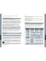
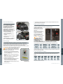
Electrical System
The circuit breaker panel, including
the 12 volt power socket and battery
isolator are located under the helm
console.
WARNING. DAMAGE TO
CHARGING CIRCUIT, LOSS
OF REVERSE ACTUATOR &
SAFETY LANYARD WILL OCCUR
IF ISOLATOR IS USED TO STOP
ENGINE.
The boat’s 12 volt electrical system
is protected through a 50 amp
thermal circuit breaker. Individual
circuit breakers protect components
such as VHF radio, bilge blower, etc.
Breaker ratings are as follows and should not be changed from those listed:
Fuse Rating Fuse Rating Fuse Rating
Accessories 20 amp Navigation lights 5 amp Footwell pump 5 amp
VHF radio 7 amp Horn 5 amp Bilge pump 5 amp
Blower 5 amp 12v socket 20 amp Reverse actuator 30 amp
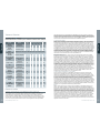
Cable Colour Codes
This chart shows the corresponding colour to all cable printed abbreviations found on board.
Code Colour Code Colour Code Colour Code Colour
BK Black LTGN
Light green
VT Violet BE Blue
GN Green BN Brown RD Red WE White
PK Pink OE Orange GY Grey YE Yellow
Example: GN/YW will signify Green/Yellow
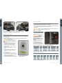
1 Pump anodes 2 Hull anode 3 Reverse bucket anode
1
3
1
2

English
16 17
www.williamsjettenders.com www.williamsjettenders.com
English
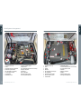
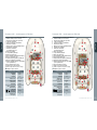
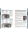
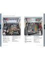
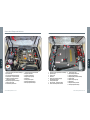
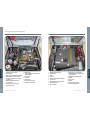
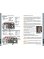
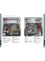
Boat System Arrangement
Dieseljet 445 & 505
Dieseljet 565 & 625
1 Coolant pressure cap
2 Oil fill
3 Fuel primer pump/secondary filter
4 Fuel/water separator filter
5 Fire extinguisher reset display
6 Coolant expansion tank
7 Seawater filter
8 Automatic greaser
9 Reverse actuator system
10 Bilge blower
11 Footwell drain pump and enclosed sump
12 Engine oil dipstick
13 Alternator
14 Fire extinguisher
15 Remote battery isolator
16 50 Amp Thermal Breaker
3
1
4
6
8 10
2
5
7
9
12
11
13
14
15
1 Coolant pressure cap
2 Oil fill
3 Oil filter
4 Alternator
5 Fire extinguisher reset display
6 Fire extinguisher
7 Fuel/water separator filter
8 Reverse actuator system
9 Seawater filter
10 Automatic greaser
11 Footwell drain pump and enclosed sump
12 Coolant expansion tank
13 Air filter
14 Engine oil dipstick
15 Battery
16 Remote battery isolator
17 50 Amp Thermal Breaker
14
1
6
8
10
13
12
2
5
7
9
11
3
4
15
16
16 17

English
18 19
www.williamsjettenders.com www.williamsjettenders.com
English
Shaft Seal Lubrication
Shaft seal lubrication is provided by an
automatic grease unit. Inspect reservoir level
approximately every 10 hours of operation. Use
a premium, multipurpose calcium sulphonate
grease or equivalent high temperature, high
speed bearing grease to re-ll reservoir. Take
care not to over-pressurise system. DO NOT
exceed maximum level indication.
Routine Maintenance
To ensure long service life and to maintain the tender in safe, good working order, please
follow these routine maintenance instructions. Williams cannot accept any responsibility
for damage or injury resulting from incorrect maintenance or improper adjustment
carried out by the owner.
1 Wash all external surfaces regularly with fresh water to remove salt deposits.
2 Inspect automatic grease unit reservoir and rell as required.
3 Check engine oil level (refer to section Oil Level Check in this handbook).
4 Check coolant level.
5 Flush open loop cooling system after each use.
6 Apply a good quality marine grease containing Teon (e.g Quicksilver 101) to all exposed
control cables.
7 Check bilges for water ingress, oil or fuel contamination and clean if necessary.
8 Check condition of anodes around pump area.
9 Slight loss of tube pressure over 24 hours is not unusual. Temperature and atmospheric
pressure will aect tube pressures. Check pressures regularly.
10 For boats used in tropical environments, the frequency of the routine maintenance should
be increased accordingly.
Servicing
The post run-in 1st service is required at 50 hours. Thereafter servicing is required
according to Maintenance Table or yearly, whichever comes first. Consult your Williams
authorized dealer for servicing.
For parts and accessories please contact your Williams authorized dealer.
Refer to Yanmar service manual for detailed schedule of engine servicing.
Winterising/Dry Storage
Store the boat covered, in a clean, ventilated and dry place that is not aected by major
variations in temperature or humidity. This is a general best practice guide. For specific
information on engine winterising, please refer to Yanmar engine manual.
Buoyancy Tube
Prior to storing over the winter periods, the buoyancy tubes should be deated and hosed
down with fresh water, removing any small stones and weed from lung track, then allowed
dry. Use a proprietary tube cleaner and polish to ensure optimum condition. Store with the
tubes lightly inated where possible.
Maintenance of the Hull & Deck
Wash the deck and stainless steel deck ttings regularly using a mild detergent in warm water
and hose down to remove sand etc. The hull and deck should be regularly polished using a
good quality gelcoat polish to minimize fade and UV chalking. Apply wax polish to hand rails
and stainless steel deck ttings.
Battery
The battery used in the Dieseljet is of the dry cell type and as such if replacing the battery
ensure only AGM type is used. This means that the electrolyte content is absorbed in a special
fabric which requires no ‘topping up’ and is leak proof in any position. When the boat is not
being used for an extended period of time, disconnect the earth terminal. A trickle-charging
device, such as an ‘Accumate’, will extend battery life.
Fuel System
A full fuel tank prevents moisture and mildew from developing within the tank. Drain water from
fuel separator.
Cooling System
Flush the open loop water circuit to remove salt, sand, shells and other contaminants that
may be trapped in the raw water cooling circuit (refer to Flushing Procedure section). Remove
engine raw water impeller if not in use for long periods. Measure the anti-freeze content of
the engine coolant with a commercially available anti-freeze tester. A 50/50 mixture of distilled
water to propylene glycol provides sucient frost protection to approx. -37°C, drain raw water
from engine OR run the same 50/50 antifreeze mixture through the open loop system via
the raw water strainer and with the isolator valve in the OFF position. See engine manual for
location of engine drain cocks.
Control Cables
Grease all control cables at both ends and exercise in and out to ensure good coverage.
General Corrosion Protection
Apply ‘Vaseline’ or similar white grease to battery isolator switch, upholstery press studs and
telescopic running light. Use maintenance spray on key switch. Apply a proprietary corrosion
guard to engine, electrical connections, under helm and around jet pump area. Wax polish
exposed stainless steel ttings and handrails.
Max

English
20 21
www.williamsjettenders.com www.williamsjettenders.com
English
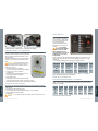
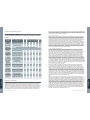
Inspection Maintenance Table
•
Check or clean
•
Replace
Please refer to engine manual for specic engine maintenance schedule.
System Item
Every
use
Regular intervals (hours)
50 250 500 1000
End of
year
Control
cables
Check operation.
Lubricate if necessary
• •
Reverse
system
Check and adjust
if necessary
• •
Hoses
(fuel & water)
Replace every 2 years or 2000 hrs, whichever comes rst
Pump
anodes
Check / replace
• •
Shaft seal &
reservoir
Check and lubricate
if necessary
• •
Bilge pump
Check operation
• •
Bilge
Inspect / Clean
• •
Footwell
sump pump
Check operation and clean
•
Navigation
lights
Check operation
• •
Blower
Check operation
• •
Electrical
connections
Clean / lubricate
• •
Impeller/
Jet pump
Check condition
• •
Fuel system
Drain full fuel system
•
Battery
Check condition
•
Limited Warranty
Williams Performance Tenders Ltd. Limited Warranty Certificate
Williams Performance Tenders (“Williams”) undertake a PDI (pre-delivery inspection) on all new boats before
shipment from factory. Williams will provide for repairs to their inatable boats during the specic warranty periods
provided herein, in accordance with the following terms, conditions and limitations. Registration of Williams boat
– Each Williams boat is supplied to the original customer with a registration card. The limited Warranty contained
herein shall not take eect and shall be deemed null and void unless the original owner submits a completed
registration card to Williams Performance Tenders Ltd, Unit 2 Vogue Business Park, Berinseld, Oxon OX10 7LN.
UK within 30 days from the date of original registration. Williams approved dealers shall be entitled to store boats
for a period of up to 6 months prior to registration provided that: a) The boats are stored in original packaging in
accordance with Williams guidelines; b) Registration is recorded upon handover with delivery hours only.
Warranty coverage:
Williams warrants to the original private purchaser of a properly registered craft that: a) All seams of the tubes,
ination valves, and the fabric used in the construction of the tube shall be free from defects in material and
workmanship for a period of 3 years from the date of the original registration; b) The fabric of the tube shall be free
from deterioration aecting serviceability (i.e. cracking, porosity, but not discolouration, fading or chang) for a
period of 3 years from the date of the original registration; c) the breglass hull shall be free from defects in material
and workmanship for a period of 2 years from the date of the original registration; d) all components tted to the
boat at the Williams factory or subsequently replaced under warranty shall be free from defects in material and
workmanship for a period of 2 years from the date of the original registration. The warranty period for commercial
use owners will be 4 months from the date of original registration. The obligation of Williams under this Limited
Warranty is limited to repairing or replacing, as Williams may elect at its sole discretion, any parts that prove, in
Williams’ sole judgement, to be defective in material or workmanship.
THIS LIMITED WARRANTY SHALL BE THE ORIGINAL PURCHASER’S SOLE AND EXCLUSIVE REMEDY.
What is not covered:
This Limited Warranty shall not apply to: a) normal wear and tear; b) any minor boat damage, including but not
limited to, gel coat crazing, fading or blistering; c) Any damage to Williams boats due to negligence, accident,
misuse, alteration, improper operation, collision, re, theft, vandalism, riot, explosion, objects striking the boat,
improper maintenance and storage; d) Any damage caused by towing a Williams boat, any damage caused by
lifting or recovering a Williams boat; e) Tubes exposed to harsh or corrosive chemicals; f) any parts installed by
anyone other than Williams factory personnel; g) any damage caused by after-market parts; h) Williams boats
purchased for commercial/governmental use; i) any work carried out on a Williams boat by an unauthorised
service centre and/or without Williams’ prior approval; j) labour, freight, delivery, storage or other similar charges;
k) defects caused or worsened by failure to adhere to the instructions concerning the treatment, maintenance and
care of the boat; l) Damage caused by water ingestion. Sometimes equipment installed on a Williams boat (such
as electronics) carry their own individual warranties provided by their respective manufacturers. In such cases any
warranty claims regarding those parts must be directed to those manufacturers and not Williams. Williams reserves
the right to make warranty coverage contingent upon proof of proper maintenance.
How to obtain Warranty repair:
Prior to any work being commenced on a Williams boat, the warranty claim must be approved in writing by
Williams Performance Tenders Ltd. In order to obtain warranty repair approval, the original owner must send written
notication, along with a copy of the bill of sale, and photograph depicting the damage and/or defect sought to be
repaired to Williams Performance Tenders Ltd, Unit 2 Vogue Business Park, Berinseld, Oxon OX10 7LN. U.K. If
Williams nds that the specic defect and/or damage is covered under this Limited Warranty, Williams will advise
the owner in writing where to send (via pre-paid freight) the boat or part(s) for repair or replacement. In many cases
the local authorised Sales and Service Centre may be utilised for repairs. In others the boat or parts must be
repaired by Williams personnel only. Williams does not assume any liability for any work performed on a Williams
boat at an unauthorised Service Centre and/or without Williams’ prior approval. All parts replaced under this
Limited warranty become the property of Williams.
Miscellaneous:
Williams does not authorise any person to create for it any other obligation or liability in connection with its boats.
THIS LIMITED WARRANTY AND WILLIAMS’ OBLIGATION HEREUNDER IS IN LIEU OF ALL WARRANTIES
EXPRESS OR IMPLIED, INCLUDING WITHOUT LIMITATION THE WARRANTIES OF MERCHANTABILITY AND
FITNESS FOR A PARTICULAR PURPOSE. Williams will not be liable for any incidental or consequential damages
resulting from breach of this limited warranty, including without limitation, loss of inatable boat use, storage,
payment for loss of time, inconvenience, boat rental expense, and local taxes required on warranty repairs.
Williams reserves the right to alter models, change colors, specications, materials, equipment, component parts,
prices or cease production of certain models at any time without prior notice, and such changes, alterations, or
cessation shall be made without Williams incurring any obligations to equip or modify inatable boats produced
prior to the date of such changes or alterations. This Limited Warranty shall be governed by and construed and
enforced in accordance with UK Law.
Page is loading ...
Page is loading ...
Page is loading ...
Page is loading ...
Page is loading ...
Page is loading ...
Page is loading ...
Page is loading ...
Page is loading ...
Page is loading ...
Page is loading ...
Page is loading ...
Page is loading ...
Page is loading ...
Page is loading ...
Page is loading ...
Page is loading ...
Page is loading ...
Page is loading ...
Page is loading ...
Page is loading ...
Page is loading ...
Page is loading ...
Page is loading ...
Page is loading ...
Page is loading ...
Page is loading ...
Page is loading ...
Page is loading ...
Page is loading ...
Page is loading ...
Page is loading ...
Page is loading ...
Page is loading ...
Page is loading ...
Page is loading ...
Page is loading ...
Page is loading ...
Page is loading ...
Page is loading ...
Page is loading ...
Page is loading ...
Page is loading ...
Page is loading ...
Page is loading ...
Page is loading ...
-
 1
1
-
 2
2
-
 3
3
-
 4
4
-
 5
5
-
 6
6
-
 7
7
-
 8
8
-
 9
9
-
 10
10
-
 11
11
-
 12
12
-
 13
13
-
 14
14
-
 15
15
-
 16
16
-
 17
17
-
 18
18
-
 19
19
-
 20
20
-
 21
21
-
 22
22
-
 23
23
-
 24
24
-
 25
25
-
 26
26
-
 27
27
-
 28
28
-
 29
29
-
 30
30
-
 31
31
-
 32
32
-
 33
33
-
 34
34
-
 35
35
-
 36
36
-
 37
37
-
 38
38
-
 39
39
-
 40
40
-
 41
41
-
 42
42
-
 43
43
-
 44
44
-
 45
45
-
 46
46
-
 47
47
-
 48
48
-
 49
49
-
 50
50
-
 51
51
-
 52
52
-
 53
53
-
 54
54
-
 55
55
-
 56
56
-
 57
57


Williams DieselJet 445 Owner's Handbook Manual
- Type
- Owner's Handbook Manual
- This manual is also suitable for
Ask a question and I''ll find the answer in the document
Finding information in a document is now easier with AI
in other languages
- italiano: Williams DieselJet 445
- français: Williams DieselJet 445
- español: Williams DieselJet 445
- Deutsch: Williams DieselJet 445
Related papers
-
Williams SportJet 520 Owner's Handbook Manual
-
Williams TurboJet Owner's Handbook Manual
-
Williams Turbojet 385s Owner's Handbook Manual
-
-
-
-
Other documents
-
Datexx SENTINA LED-92M Owner's manual
-
Yanmar 4JH4-TE Operating instructions
-
-
Sea Ray 340 Sundancer Owner's manual
-
PURSUIT 2011 Offshore-375 Owner's manual
-
Regal 26 XO Owner's manual
-
-
-
-