Page is loading ...

GB
Oil-hydraulic actuator to operate swinging gates up to 4 meters
Instructions manual
pages 13-24
13

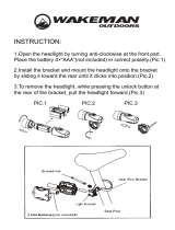
APPLICATION OPTIONS DEPENDING ON GATE WIDTHS
1.0m
stroke 150
2.0m 2.5m 4.0m
stroke 280
stroke 400
with an electric lock
stroke 280
IMPORTANT:
The Gate Post and the gate Hinges
must be suitable to take the
weight and
inertia effects generated during the
opening and closing operations.
= with gate wings wider than 2.0 metres each,
an electric lock is needed.
(*)
(*)
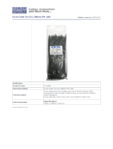
883 84 BB5
Freno A/C
Braking O/C
avec Frein O/F
Working 280mm
meccanica
FADINI
Power
Supply voltage
Absorbed current
Maximum pressure
rpm motor
IP
OIL FADINI
300W
230V - 50Hz
1,3 A
30 atm
1350
67
-25°C +80°C
www.fadini.net
made in italy
Item number, "Price list" refers
N = Non locking in Opening
B = Locking in Closed position
BB = Double locking
Bar code
locking options:
Pump type "P3 or P5"
Braking version reference
•
in closing - code No. 77 -
•
in opening/closing - code No. 84 -
Strokes 150mm, 280mm, 400mm
Technical data
PIC. 1
PRELIMINARY WARNINGS FOR SAFETY AND PROPER SYSTEM OPERATION
- Site inspection, installation, testing, risk analysis and after sale service/maintenance must be carried out by qualified and authorized technicians
- This automation is designed for a specific scope of applications as indicated in this manual, including safety, control and signalling accessories
as minimum required with "Fadini" equipment.
- Any applications not explicitly included in this manual may cause operation problems or damages to properties and people.
- Make sure the gate is correctly mounted and opening/closing movements are smooth, without any friction or jerking.
- Verify that the gate is perfectly levelled in the vertical position and both upper and lower hinges are well lubricated and smooth running.
- Make sure that rigid gate stops are mounted in both open and closed gate stop positions.
- Ensure that the mains and voltage supplied to the motor is 230V ±10% 50Hz.
- Hindi 880 must be powered with cables having wires with 1.5 mm
2
section, maximum distance of 50 meters. For distances longer than 50 meters,
it is recommended that wires with suitable sections in compliance with good installation requirements be used.
- In case parts or accessories are needed as replacements, use only Fadini originals as recommended by the manufacturer.
- Meccanica Fadini is not liable for damages caused by the incorrect use of the equipment, or for applications not included in this manual or for
malfunctioning resulting from the use of materials or accessories not recommended by the manufacturer.
- The manufacturer reserves the right to make changes to this manual without prior notice.
Code of brake type
English
14

13
FADINI
FADINI
1
2
3
4
9
8
7
5
6
10
12
11
14
15
16
17
To suit 400mm
1 - 2 x Coded keys opening the sliding lid
2 - Cover plug
3 - Anodized aluminium cover
4 - Internal manual release key
(only with the versions Hindi 880 Locking Close & Double Locking)
5 - Rear protection cap
6 - Cable gland
7 - Oil-hydraulic actuator - Stroke 150mm
- " 280mm
- " 400mm
8 - 2 x Tie rods to fix the cover
9 - 2 x Hex. grommet nuts to fix the front cover plug
10 - Ball bearing joint spanner
11 - Front fixing plate, Hindi 880 - 150mm and 280mm
12 - Front fastening circlip
13 - Front fixing plate, Hindi 880 - 400mm
14 - M12 self-locking nut
15 - Rear plate, gate post fixing
16 - M12x40 rear fixing screw
17 - Cap fixing stud
18 - Patch plate, rear fixing 150x150mm - (optional) code 8311
19 - Patch plate, front fixing120x120mm - " code 8310
20 - Patch plate, front fixing 84x84mm - " code 8312
COMPONENTS AND ACCESSORIES INCLUDED
Patching plates
(OPTIONAL)
18 19 20
PIC. 2
PRELIMINARY INSTRUCTIONS BEFORE INSTALLATION
FOR A CORRECT INSTALLATION IN ORDER TO ACHIEVE A GOOD PERFORMANCE OF HINDI 880 IT IS RECOMMENDED TO KEEP TO THE
FOLLOWING INSTRUCTIONS AND DIAGRAMS.
IMPORTANT: INSTALLATIONS SHOULD BE CARRIED OUT BY QUALIFIED TECHNICAL AGENTS ONLY, IN COMPLIANCE WITH THE SAFETY
NORMS EN 12445 - EN 12453 AND THE 2006/42/CE MACHINERY DIRECTIVE. ALSO CARRY OUT AN ACCURATE RISK ANALYSIS IN RESPECT
OF THE EXISTING SAFETY REGULATIONS.
Meccanica Fadini, as manufacturer, is not liable for installations failing to meet the rules of good fitting technique and for applications not
included in this manual.
GENERAL INFORMATION
HINDI 880 is an oil-hydraulic automation for external use, designed to open and close swinging gates of any shapes and sizes. It is an oil-hydraulic
product and therefore offers all the advantages of hydraulic operations such as reliability, smoothness and adjustable minimum and maximum pressure
valves, versatility of application, being suitable for any type of swinging gates.
It is operated by an electronic control box, installed outside in a protected place; operations can be fully automatic or semi-automatic, depending on the
application requirements.
A variety of accessories complete the system to ensure safety and full control of it at your finger tips, making Hindi 880 suitable for any installation
requirements in either commercial, industrial or residential applications.
For a correct installation of the operator, it is important that the fitting dimensions be respected as indicated on page 14, Pic.1
and page 17, Pic. 6-7-8.
English
15

10
The electric cable for power supply
must dangle loosely during opening
and closing movements.
PIC. 3
Cut to measure. See
distance B (page 17).
GATE
Metal reinforcement plate: provide a suitable
strengthening plate (
optional) to the fixing
bracket, depending on the type of gate
involved, specially with heavy gates.
PLEASE NOTE: When the front fixing is
welded, make sure to suitably protect the
shaft during this operation.
PIC. 4
IMPORTANT: with heavy gates, the installer
must properly strengthen the fixing both to
the gate post and gate with rigid metal plates
(not supplied by manufacturer), depending
on the application requirements (Pic.4).
!
Make sure the actuator is levelled in
any directions before welding.
Rear
bracket
B
Front
bracket
ELECTRICAL LAYOUT AND ACCESSORIES
Before installing Hindi 880 set up all the
safety and commanding accessories, at
least as minimum required. Pic.3.
!
1 - Flasher Miri 4 with aerial
2 - Controller Elpro 13 exp (*)
(most important: it must be kept sheltered and dry)
(*) with plug-on receiver Astro 43/2 R M.Q.B.
3 - 230V - 50Hz 0.03A magneto-thermal
differential circuit breaker
(beyond 100m use 2.5 mm
2
section wires)
4 - Photocell receiver FIT 55 recess mount
5 - HINDI 880 oil-hydraulic actuator
6 - Gate stop in closed gate position
7 - Electric lock for Hindi 880 Non-locking (**)
(**)
and for gates wider than 2.0m each
8 - Photocell projector FIT 55 recess mount
9 - Gate stop in open gate position
10 - Transmitter Astro 43/2 TR Small
11 - Post fixing base plate (***)
(***) complete with base plate cover
12 - Anodized aluminium 0.5m post
13 - Key-switch CHIS 37 recess mount
14 - Anodized aluminium 1.20m post
code 4602
code 7079
code 4329
(NOT included)
code 551
(NOT included)
code 7083
code 551
(NOT included)
code 4321
code 554
code 555
code 371
code 557
FIXING GEOMETRY DEPENDING ON THE TYPE OF "ACTUATOR"
After checking the fixing dimensions as indicated on page 17 (Pic.6, Pic.7 and Pic.8), weld
the rear and front brackets to the respective patch plates (Pic.4).
!
!
14
11
4
9
9
12
8
10
1
5
5
6
13
4 x 1.0
4 x 1.0
2 x 1.0
4 x 1.0
7
2 x 1.0
2 x 1.0
4 x 1.0
4 x 1.0
3 x 2.5
2
2 x 1.0
RG 58
3
8
4
POWER SUPPLY
230V ±10% 50Hz
SINGLE-PHASE
230 VOLT
NEUTRAL
LIVE
English
16

PIC. 5
Before fixing HINDI 880 to the gate post and gate, power
supply the actuator and drive the shaft fully out; then swap
the electrical live connections and drive it 5-6 mm in.
IMPORTANT: the ball bearing joint must ALWAYS be fully
tightened by means of the lock nut (Pic.9).
12.5µF
starting
capacitor
1
2
,
5
μ
F
common
BLUE
230 Volt
50 Hz
MANUAL TEST
!
5-6mm
SCREW IN
PIC. 6
stroke 150mm
•
Gate post fitting geometry
•
"B" 80mm
"A" 60mm
Leave 1cm clearance
between the cover and closed gate
opening 95°
Gate stop in
closed position
Shaft travel 150mm
Shaft travel 280mm - BRAKING 260mm
"B" 130mm
"A" 130mm
80
opening 95°
PIC. 8
Shaft travel 400mm - BRAKING 385mm
PIC. 9
UNSCREW 5-6mm
NOTE WELL:
tighten the lock nut hard
!
Rear Fixing
Hindi 880 actuator
Front Fixing
Hindi 880 actuator
1734
- With the BRAKING version
distance "A" must be 120mm -
BRAKING 160mm
"B"
180mm
155
opening 95°
Gate stop in
closed position
"A"
210mm
MANUAL TEST OF THE ACTUATOR
!
INSTALLATION OF THE "ACTUATORS"
stroke 280mm
•
Gate post fitting geometry
•
PIC. 7
Gate stop in
closed position
Leave 1cm clearance
between the cover and closed gate
stroke 400mm
•
Gate post fitting geometry
•
Leave 1cm clearance
between the cover and closed gate
- With the BRAKING version
distance "A" must be 200mm -
Once the installation of the brackets is completed, unscrew the ball bearing joint by 5-6 mm: in this way the actuator keeps pushing the gates to
closing and a better hold is achieved in closed gate position. It is most important to tighten the lock nut very well (a special spanner is supplied
and a wrench x 19 to be provided for this job - Pic.9). Fix Hindi 880 on to the rear bracket by the screw and to the front bracket by the circlip, both
incuded in the equipment (Pic.9 - 10).
Spanner supplied with equipment:
it allows to hold the shaft while the
lock nut is being tightened with a
wrench x 19
- (NOT included) -
Wrench x 19
PIC. 10
Wrench x 19
Wrench x 19
English
17

PIC. 11
DIP-SWITCH
ON
OFF
1 456 7823
L1
L6
L3
L4
L5
L2
28
26
27
TERMINALS FOR THE
CONNECTIONS TO
PULIN 3 PUSH BUTTONS
Transformer
230V - 24V
-
+
DELAY TIME
GATE CLOSING
0s - 18s
Motor M1
12.5 µF
capacitor
Motor M2
12.5 µF
capacitor
-
+
DWELL
TIME
0s - 120s
-
+
MOTOR RUN TIME
2s - 100s
F1= 5A
Line fuse
F2= 5A
Line fuse
Flasher
fuse
F3= 630mA
Transformer
fuse
F4= 630mA
Opening Delay
Relay
Closing Delay
Relay
Line relay
Motor M2
direction relay
Fuse 24V
F5= 1A
Motor M1
direction relay
Elpro 13
PLUG-IN RADIO CARD
CONNECTOR
Elpro 13 exp FADINI
1 2 3 4 5 6 7 8 9 10 11 12 13 14 15 16 17 18 19 20 21 22 23 24 25
M1 M2
NC CONTACT
2
nd
pair PHOTOCELLS
NC CONTACT
1
st
pair PHOTOCELLS
COMMON
OPEN NO
CLOSE NO
STOP NC
RADIO NO
COMMON
12V AC, 15VA OUTPUT
ELECTRIC LOCK
SUPPLY
24V 3W max pilot light
24V 250mA OUTPUT max. load:
- 2 pairs photocells
- 1 Radio receiver
NC SAFETY CONTACT
MOTOR M1 OUTPUT
230V SINGLE-PHASE
MOTOR M2 OUTPUT
230V SINGLE-PHASE
FLASHER
230V - 25W max
COMMON
COMMON
230 VOLT
NEUTRAL
LIVE
IMPORTANT:
- The control board must be installed in a protected, dry place inside the box provided with it.
- Fit a high sensitivity, 0.03A, magneto-thermal, differential circuit breaker (Pic.3, page 16) to the
control board power supply.
- Make sure that power supply is 230V ±10% 50Hz.
- For the power supply to the board and flasher use 1.5mm
2
section wires (up to 50m distance);
for the accessories use 1mm
2
section wires and connect the yellow/green cable - i.e. Ground -
to the electric motor/s (Pic.11).
- Link out terminals 1 - 2 if no Photocells are used, and bridge the respective terminals if the 2
nd
pair is not used either.
- If no Button- or Key-switches with stop button are used, link out / bridge the NC contacts of
terminals 3 and 6.
!
It is important to follow the instructions
enclosed in the "Elpro 13 exp" box.
Electronic board with microprocessor designed to control
double swinging gates.
1
2
3
4
5
6
200
182
260
280
110
English
18

Switch setting
DIP-SWITCH:
1 456 7823
ON
OFF
1= ON 1
st
pair Photocells. Stop in Opening cycle
2= ON Radio. No reverse in Opening cycle
3= ON Automatic Closing
4= ON Pre-flasing
5= ON Radio. Step by step, stop in between
6= ON Pedestrian opening of one gate, gate in closed position
7= ON Stroke Reversing Mode on pulsing to Open, gate closed
8= ON No Gate Delay on Opening. Both motors start together
12
13
1
2
1
DIP-SWITCH 1 (only 1
st
pair photocells):
ON: Photocells stop gates on opening and
reverse on closing once obstacle is removed
OFF: Photocells do not stop gates on opening
and reverse on closing in case of obstacle
TERMINAL BOARD - Electronic board
low voltage
Photocells:
1 2 3 4 5 6 7 8 9 10 11 12 13 14 15
Receiver Projector
1
st
pair Photocells (the ones fitted on to the gate posts),
controlled by Dip-Switch 1.
2
nd
pair Photocells (the ones fitted inside the gateway),
always stop the gates on opening and reverse travel direction
on closing once obstacle is removed
NC CONTACT
2
nd
pair
PHOTOCELLS
NC CONTACT
1
st
pair
PHOTOCELLS
24Vac OUTPUT(MAX LOAD:
2 PAIRS PHOTOCELLS
1 RADIO RECEIVER)
Terminal board - Elpro 13 exp -
3
STOP NC
OPEN NO
CLOSE NO
Switch with custom-
-coded key:
456
COMMON
FADINI
Lock barrel
EUROPEAN PROFILE
FADINI
Lock barrel
UNIVERSAL PROFILE
2
ON: No reversing in opening
OFF: Each pulse reverses travel
DIP-SWITCH 2:
ON: Step by step, stop in between
5
OFF: Normal functioning as pre-set
DIP-SWITCH 5:
7
3
COMMON
RADIO
RECEIVER
NO
Radio contact:
- Open/Close (normal)
each pulse reverses
gate travel direction
- Step by step
stop in between
Electric lock:
10
9
12V AC, 15VA OUTPUT
ELECTRIC LOCK
POWER SUPPLY
Device to mechanically hold the gates in closed position
recommended with gates wider than 2 meters and in case
non locking actuators are fitted.
Time of activation: on powering for 2 seconds, 100ms in
advance against gate motion.
Gate movement signalling:
1
1
24V 3W max
Indication light
8
COMMON
Light On = Gate open
Light Off = Gate closed
Flashing 0.5s (fast) = Gate closing
Flashing 1s = Gate opening
14
15
Safety contact:
NC SAFETY
CONTACT
Microswitch fitted to the box lid.
If not used, link out the terminals
14 and 15.
Elpro
•
13 exp
IMPORTANT
Connect all the
- yellow/green - cables
to GROUND
!
14 15
English
19

COMMON
M1 M2
COMMON
TERMINAL BOARD -
electronic board
voltage connections
16 17 18 19 20 21 22 23 24 25
Electric motors:
Once connections to the electric motors have been completed,
the three timers as follows are to be set:
Gate Delay on Closing, Dwell Time and Motor Run Time.
8
ON: Gate delay on Opening out of service.
Both motors start together
OFF: Gate delay on Opening in service
DIP-SWITCH 8:
ON=
Automatic closing
3
OFF= No automatic closing.
Semi-automatic mode,closing by pulse.
DIP-SWITCH 3:
16 17 18 19 20 21
MOTOR OUTPUT M1
230V SINGLE-PHASE
(It operates the 1
st
gate
wing and Pedestrian mode)
MOTOR OUTPUT M2
230V SINGLE-PHASE
+
_
+
_
+
_
GATE DELAY TIME ON CLOSING
0s - 18s
DWELL TIME (with Dip-Switch 3=ON)
0s - 120s
MOTOR RUN TIME
2s - 100s
Terminal boards - Elpro 13 exp -
POWER CONNECTIONS
l'apricancello
22 23
Flasher:
FLASHER
230V - 25W max.
Pre-flashing. Dip-Switch 4=ON:
Once a commanding pulse is given,
the light starts flashing and after 3
seconds the actuators start operating.
ON: Pre-flashing
4
OFF: No pre-flashing
DIP-SWITCH 4:
24 25
230 VOLT
Power supply to the controller:
POWER SUPPLY INPUT
230V ±10% 50Hz SINGLE-PHASE
Fit a 0.03A High sensitivity, Magneto-thermal, Differential circuit
breaker to the mains to the controller.
Supply the board with 230V ±10% 50Hz single-phase voltage, once
all the power and low voltage connections have been completed.
-
+
Automatic / Semi-automatic:
DWELL TIME
0 seconds - 120 seconds
ON= Automatic closing
3
OFF= No automatic closing.
Closing by pulse.
DIP-SWITCH 3:
Automatic Cycle
: on pulsing to Open, the gates move to open; are held
open for a time as set by the dwell timer, on expiring they are driven to close
automatically.
Semi-automatic Cycle
: on pulsing to Open, the gates are opened; another
pulse is needed to close them.
Pedestrian Opening:
ON= Only one gate is opened
6
OFF= Normal Operating Mode
DIP-SWITCH 6:
The pedestrian opening is allowed for one gate wing, in closed position.
Dip-Switch n°6=ON
- Pulse the terminals 3-4 to open
:
- the first Open pulse operates
Motor 1;
- a second pulse, to terminals 3 and 4, operates the second gate wing.
The remote control always operates both gate wings, through the Radio
contact, terminals 7-8.
Stroke Reversing
Pulse:
ON: Stroke Reversing Pulse in service
with gate in closed position
7
OFF: Stroke Reversing Pulse out of
service
DIP-SWITCH 7:
This function
(Dip-Switch n°7=ON)
facilitates the release of the electric
lock with the gates in fully closed position, even on
pedestrian opening
mode: the gates in closed position, before being opened, are pushed to
close for 2 seconds.
Step by Step:
ON: Step-by-step mode in service
5
OFF: Step-by-step out of service
DIP-SWITCH 5:
Dip-Switch n°5=ON
:
By pulsing the Radio contact, the automation goes through
open-stop-close-stop operations step by step.
43
COMMON
COMMON
OPEN
NO
External clock
External Time Clock (Optional):
-
+
DWELL TIME
0 seconds - 120 seconds
ON= Automatic Closing
3
OFF= No Automatic Closing.
Semi-automatic by pulsing
DIP-SWITCH N°3=ON Automatic Closing:
TIME CLOCK
: the Elpro 13 exp controller allows the connection of a time
clock to open and close the gates.
W
iring: parallel connect the NO contact of the clock to terminals No.4
OPEN and No.3 COMMON, set Dip-Switch No.3=ON Automatic Closing
and adjust the Dwell Time as required.
Functioning: set the opening time on the clock. At the set time the gates
are opened and held open (the flasher switches off and the indication
light gives out two quick flashes followed by a longer pause). No further
command is accepted (not even by remote control). On elapsing of the
clock time and after the dwell time the gates are automatically reclosed.
12
6
39
English
20

HORIZONTAL
For manual release give
1-2 turns anti-clockwise
12
6
39
The manual release of Hindi 880 system allows to manually operate gates fitted with actuators, locking type. The coded key is
supplied with the equipment and must be inserted in the casing lock and turned by 90° anti clockwise in order to be able to
slide the hatch cover to open.
The manual release key is already inserted and must be turned anti clockwise once or twice. When the manual operations are
completed, the hydraulic circuit must be relocked by turning the release key clockwise to tighten the valve screw firmly (Pic.12).
Screwdriver to
adjust the
thrust force
The thrust force must be adjusted in open and close cycles by loosening or tightening the adjusting screws (Red and Green);
these are located inside the valve casing, which can be accessed by using the coded key (Pic.13).
Lock catching plate
fitted to the gate reaching the
closing stop first (1
st
)
•Gate holding bolt
welded to the gate wing that
closes first.
•Gate stop to be fixed to the
ground.
Electric lock fitted vertically
fixed to the ground with catching
plate and gate stop.
HINDI 880 MANUAL RELEASE - DOUBLE LOCKING AND LOCKING CLOSE VERSIONS -
PIC. 12
FADINI
FADINI
90°
Internal key for
manual release
Encoded key.
insert the key and rotate it 90°
anti clockwise to have access
to the casing.
PIC. 13
ADJUSTING THE THRUST FORCE
Green screw = to adjust the thrust force in opening cycle
• clockwise: + Force
• counter clockwise:
_
Force
Red screw = to adjust the thrust force in closing cycle
• clockwise: + Force
• counter clockwise:
_
Force
BRAKING
•
ADJUSTMENT
•
CLOSING CYCLE
!
ATTENTION.
It is possible to adjust the "BRAKE" in
closing cycle by the actuator head:
be careful, it is very sensitive.
In opening, cycle braking is factory set.
12
6
39
_
12
6
39
+
Brake
INSTALLING THE ELECTRIC LOCK
PIC. 14
PIC. 15
VERTICAL
code 7083
"Vertical" Electric lock
fitted to the foot of the gate
that arrives second (2
nd
).
PIC. 16
It is recommended that an
electric lock be fitted with
Hindi 880's Non locking
(no hydraulic locking device)
and with gates wider
than 2.0 meters
(Pic.15 and Pic.16).
code 7081
"Horizontal" electric lock
to be fitted to the gate that closes second (2
nd
) and catches the latching
bolt, firmly holding the gates in closed position.
English
21

Right-hand opening
Hindi 880 installed
CUT to get
a suitable opening
for cable leading
STUD
for fixing the cap
95°
90°
The two gate stops in
open and closed positions
ARE NOT INCLUDED
!
INSTALLING THE GATE STOP "PROVIDED BY THE INSTALLER"
PIC. 17
Gate post line
Gate stop
Gate stop in closed position
to take the electric lock bolt
Gate stop
FITTING THE PROTECTION CAP
PIC. 18
RED
BLUE
RED
YELLOW/GREEN
Rear fixing plate
to weld
PROTECTION CAP
with opening
ATTENTION:
the electric power cable must be
ALWAYS positioned along the side of the rear
"
fixing plate" between the bolt and the actuator rear
casting (Pic.18); and it must be pulled into the
cable lead and through the hole in the
=
PROTECTION CAP = (Pic.19).
!
4
x
1
.
0
FITTING THE COVER AND THE REAR CAP
Rear fixing plate
CURVE the electric
cable through
Left-hand Opening
Hindi 880 installed
CUT to get
a suitable opening
for cable leading
4x1.0mm
2
power
supply cable, included
IMPORTANT
Connect all the
cables to GROUND
!
PIC. 19
COMPLETE
2 x grommet
nuts
Cover end plug
Cover Tie rods Front fixing plate Oil-hydraulic actuator
Valve block
including max. / min.
pressure valves and
manual realease
English
22

Manufacturing company:
Model:
On-the-gate oil-hydraulic operator for swinging gates
Hindi 880 is to be sold and installed as a comprehensive "Automatic System", including the accessories and
the components as recommended by the Manufacturing Company.
In observance of the current directives, any automation is to be regarded as a "machinery". Therefore it is
required that all the applicable safety norms are strictly complied with by the installation agents, who are also
required to issue a Declaration of Conformity.
The manufacturing company is not liable for incorrect applications or misuse of its products that are
declared to be produced in compliance with the following norms:
- Analysis of the risk and actions to cure them:
EN 12445
&
EN 12453
- Low Voltage Directive
2006/95 CE
- Electro-magnetic compatibility Directive
2004/108/CE & 92/31 CEE
Address:
meccanica
FADINI
F
snc.
IS IN COMPLIANCE WITH THE NORMS ......... 2006/42/CE
AND THAT:
In order to certify the product the Manufacturing Company declares under its own responsibility
the compliance with the PRODUCT NORM .........................
EN 13241-1
Date:
DECLARES UNDER ITS OWN RESPONSIBILITY THAT:
DECLARATION OF CONFORMITY
of the Manufacturer
GB
made in Italy
Meccanica Fadini s.n.c.
Direttore Responsabile
The Responsible Manager
03-03-10
Via Mantova, 177/A - C.P. 126 - 37053 Cerea (VR) Italy
Tel.+39 0442 330422 r.a. - Fax +39 0442 331054
e-mail: [email protected] - www.fadini.net
Q
U
A
L
I
T
Y
I
N
M
O
T
I
O
N
English
23

Power Yield 180W (0.25HP)
Supply voltage 230V
Frequency 50Hz
Absorbed current 1.3A
Absorbed power 300W
Motor revolutions 1
.
350 rev./1'
Capacitor 12.5µF
Intermittent service S3 - 25%
OVERALL DIMENSIONS
PIC. 20
ELECTRIC MOTOR TECHNICAL DATA
"HINDI 880" FEATURES
Rear view
117
94
12
94
117117
80
15
l
92
C
Electric cable
4x1
l=750mm
Rear fixing
plate
Side view
Front view
Front fixing plate
150mm and
280mm stroke
125
50
150
12
93
82
94
l
C
82
40
95
Plan view
OIL-HYDRAULIC PISTON TECHNICAL DATA
Pump flow rate - P5 1.4 l/min.
Piston diametre 45mm
Shaft diametre 20mm
Thrust power (10 bar) 1
.
000N
Thrust power (30 bar) 3
.
000N
Mean working pressure 1 MPa (10 bar)
Maximum pump pressure 3 MPa (30 bar)
Hydraulic oil type Oil Fadini
Working temperature -25°C +80°C
Maximum gate weight 180Kg
Protection grade complete IP 553
MODEL
OPENING
TIME
DWELL
TIME
CLOSING
TIME
REST
TIME
TIME OF ONE
COMPLETE
CYCLE
COMPLETE
CYCLES
Opening - Dwell -
Closing - Dwell
CYCLES
PER YEAR
with 8 hours'
service per day
Stroke 150mm
Stroke 280mm
Stroke 400mm
12 sec.
24 sec.
32 sec.
30 sec.
30 sec.
40 sec.
12 sec.
24 sec.
32 sec.
40 sec.
40 sec.
50 sec.
94 sec.
118 sec.
154 sec.
N°39/h
N°30/h
N°23/h
N°112
.
000
N°86
.
000
N°66
.
000
WEIGHT
9.5 Kg
11 Kg
14 Kg
Fast - pump P10
(for specific applications)
280mm
400mm
12 sec.
16 sec.
50 sec.
106 sec. N°34/h N°97
.
000 11 Kg
120 sec. N°30/h N°86
.
000 14 Kg
meccanica
FADINI
F
Via Mantova 177/A - C.P. 126 - 37053 Cerea (VR) Italy - Tel. +39 0442 330422 - Fax +39 0442 331054
e-mail: [email protected] - www.fadini.net
The manufacturing company reserves the right to amend this manual without prior notice and is not liable for incorrect applications and damages to people and properties.
For the system to operate to its best performance level over the time and in compliance with the safety norms, it is recommended that
proper maintenance and inspection of the entire installation be carried out, including the gate operator/s, electronic equipment and cables.
The entire installation must be executed by qualified technicians following the guidelines of the Safety Norms handbook available on
request, and to be filled in, where required:
- Oil-hydraulic equipment: inspection and maintenance at least every 6 months.
- Electronic equipment and safety accessories: inspection and maintenance at least once a month .
- Ordinary and extraordinary maintenance and service to be agreed between the installation agent and customer /end user.
- Dispose properly of packaging materials such as cardboard, nylon, polystyrene, etc. through specialized companies.
ATTENTION Important
!
DISPOSE PROPERLY OF ENVIRONMENT-NOXIOUS MATERIALS
The growth of MECCANICA FADINI has always been based on high
quality products and on a TOTAL QUALITY CONTROL SYSTEM
ensuring the consistency of the quality standards over the time as
well as constant updating with the European Norms in the framework
of a process of continuous improvement.
English
24
/