INTRODUCTION
Congratulations on your choice of a BISON gear motor.
All items included in Benincà’s wide product range stem
from twenty year of our experience in the sector of automatic
systems, always striving to find new materials and advanced
technologies.
For this reason, nowadays we are able to offer you extremely
reliable products that, thanks to their power, efficiency and
long-lasting features, entirely meet the end user’s require-
ments.
All our products are covered by a guarantee.
Furthermore, an R.C. insurance policy signed with a primary
insurance company, covers any injuries or damages caused
by manufacturing faults.
GENERAL INFORMATION
Automatic system with 230V AC, single-phase power sup-
ply for industrial use, sliding gates. It is available in two
versions:
BISON 20 OM 230VAC, for gates with 2000 kg max weight
BISON 25 OTI 230 VAC (with three-phase motor and Inverter)
with gates with 2500 kg max weight.
Both motors are equipped with anti-crash electronic device
(encoder) and electronic braking.
The 25 OTI version is also equipped with three-phase inverter,
which allows to achieve the performance of a three-phase
motor, while maintaining the simplicity of a single-phase
connection.
SPECIFICATIONS
BISON20 OM BISON25 OTI
Mains power supply
230Vac 50/60Hz
Motor power supply
230Vac single-phase 230Vac three-phase
Consumption
3,0 A 8,0 A
Thrust
1110 N 2500 N
Inverter
NO YES
Operating jogging
Heavy duty
Protection level
IP44
Operating temperature
-20°C / +50°C
Capacitor
31,5 μF
Gate max. weight
2000 kg 2500 kg
Rack module
M4 Z 18
Opening speed
10,5 m/min 10,5 m/min
Noise level
<70 dB
Lubrication
AGIP BLASIA 32
Weight
30 kg 31 kg
PRELIMINARY CHECKS
For a good operation of the automatic system for sliding
gates, the gate/door to be automated shall feature the fol-
lowing characteristics:
- the guide track and related carriers should be adequately
sized and subject to maintenance (in order to avert exces-
sive friction during the gate sliding).
- during operation, no excessive oscillations should be re-
ported to the gate/door.
- the opening and closing stroke should be limited to a
mechanical stop (according to the current safety regula-
tion).
These preliminary checks are MANDATORY. It is expressly
FORBIDDEN to use the BISON automatic system on doors
and gates not in good conditions or that have not undergone
a correct maintenance.
INSTALLATION
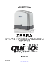
OVERALL DIMENSIONS
Figure 1 shows the overall dimensions of the gear motor,
expressed in mm.
Given the remarkable weight of the actuator, the device
should be handled by at least 2 persons.
Loosen the 4 “A” screws (Fig. 1) and entirely remove the
front side of the system. Now all elements of the systems
can be accessed.
If only the control unit is to be reached, it is sufficient to re-
move the 4 “B” screws by lifting the upper cover.
The niches for the photocell mounting (F) are provided on
the motor removable side.
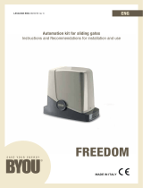
FOUNDATION PLATE - DIMENSIONS
Fig.2 shows the installation dimensions of the foundation
plate, expressed in millimetres. Two holes have been drilled
on the plate for the passage of cable. When the corrugated
pipe is introduced, keep in mind that the hole to be used is
the one shown in Figure 2 (ref. C).
The plate should be positioned at 15mm from the floor (with
possible adjustment +/- 5mm), 15 mm above floor-level
usually avert any water stagnation.
At this height, the lower edge of the rack tooth should be
at 132 mm.
If the rack is already installed, a fitting base, raised with
respect to the floor, should be required. However, it is not
advisable to lower the fitting surface.
If the rack used is the model RI.M4Z, the edge of the plate
should lie perfectly parallel with respect to the door leaf and
should be positioned at 16 mm. If a different rack is used,
find the correct distance by temporarily fitting it to the door/
gate leaf, then place the gear motor and check that the pinion
and the rack are geared together.
INSTALLATION OF THE FOUNDATION PLATE
Provide for an adequate hole for the foundation.
Prepare the plate by fitting the foundation bolts, as shown in
Fig. 3: Tighten the 4 D1 nuts to the foundation bolt T, then
insert the plate and fix it with washers and the 4 D2 nuts.
Pour cement on the plate (Fig. 4), taking care that the plate
level should lie perfectly flat. Check that the threaded inserts
(I) for the fitting screws are clean and cement free.
Wait that the cement hardens, then remove the D2 nuts and
R washers (Fig. 5), remove the plate, reinsert the D2 nuts and
washers and then replace the plate.
Note: It is also possible to use highly resistant special dowels
to fix the foundation plate onto the floor. In this case, make
sure that there is no water stagnation.
In any case, the foundation plate should be adequate to the
stress exercised on the automatic system.
HOW TO FIT THE GEAR MOTOR
Place to gear motor on the foundation plate, as shown in Figu-
re 6, by inserting the slots “F” on the threaded inserts “I”.
Fix the gear motor to the base, by using the washers R, the
threaded washers Z and nuts D.
The threaded holes allow for the horizontal movement of
the gear motor, which is required to gear/ungear the pinion
to the rack.
HOW TO ADJUST THE HEIGHT OF THE GEAR MOTOR
By acting on the nuts under the foundation plate, the height
of the gear motor can be adjusted (Fig. 7).
Do not raise the plate for more than 20 mm in order not to
exercise excessive stress onto the foundation bolts.