Legrand Evolution Series 6" Poke-Thru Devices Installation guide
- Category
- Motorcycle Accessories
- Type
- Installation guide

1
Wiremold electrical systems conform to and should be properly
grounded in compliance with requirements of the current National
Electrical Code or codes administered by local authorities.
All electrical products may present a possible shock or fire
hazard if improperly installed or used. Wiremold electrical products
may bear the mark as UL Listed and/or Classified and should
be installed in conformance with current local and/or the National
Electrical Code.
Products Covered: 6ATCP, 6ATP, 6ATCPAV, 6ATPAV, 6ATC, 6AT, 6STC, 6CTC, 6CT, 68REC, 68MAAP, 682A, 68B, 6DP,
6DEC, 6S1, 6S2, 6MAAP, 6AAP, 6MAAP2A, 6B, 6TS, 6STCP, 6STCPAV, 575CHA, 5PTHA, 5BLH,
175CHA, 1125CHA, 1PTHA, 1BLH, CE6STCP, CE6STCPAV
CAUTION: DO NOT operate tile stripper, cleaning, or resurfacing equipment over top of covers. This may result in
damage to the surface finish of the product.
Suitable for use in air handling spaces in accordance with Sec. 300-22 (C) of the National Electrical Code.
Evolution
™
Series
6" Poke-Thru Devices
I N S T A L L A T I O N I N S T R U C T I O N S
Installation Instruction No.: 1 007 154 R2 – Updated May 2010
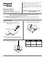
CAUTION: Be certain to locate hole at least 6" [152mm] from any wall or
pillar to leave enough room for Poke-Thru cover assembly.
IMPORTANT: Please read all instructions
before beginning.
CAUTION: Minimum spacing of 2ft on center and not more
than one device per each 65 square feet of floor
area in each span.
Step 2 Remove 6 1/2" dia. [166mm] section from
carpet or tile. Use template provided.
Step 1 Layout and locate position of hole(s).
Step 3 Create core hole according to the
dimensions provided in the chart.
FLOOR PREPARATIONS
24" [610mm] Min
Center – Center
6 1/2"
[166mm]
Covered Floors 6" [152mm] 6 1/8" [156mm]
(Carpet, Tile or
Wood)
Bare Concrete 6 1/16" [154mm] 6 1/8" [156mm]
or Terrazzo
FLOOR CORE CORE
TYPE SIZE (Min.) SIZE (Max.)

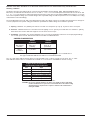
CONVENTIONAL WIRING SCHEMATIC ISOLATED GROUND WIRING SCHEMATIC
BLACK or HOT BLACK BLACK or HOT BLACK
From branch circuit from Poke-Thru receptacle From branch circuit from Poke-Thru receptacle
WHITE or NEUTRAL WHITE WHITE or NEUTRAL WHITE
F
rom branch circuit from Poke-Thru receptacle From branch circuit from Poke-Thru receptacle
GREEN or GROUND GREEN ISOLATED GROUND GREEN
From branch circuit from Poke-Thru receptacle From branch circuit from Poke-Thru receptacle
S
ystem Ground
GREEN or GROUND
GREEN (jumper wire)
From branch circuit from Poke-Thru
S
ystem Ground junction box
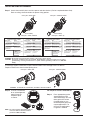
2
Step 3 Place appropriate gasket
around poke thru and
slide under flange. Use flat
foam gasket for surface
tile applications or use
round neoprene gasket for
carpet applications. For
the flush tile applications
no gasket is needed.
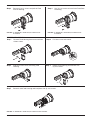
Step 1 Attach data and AV plates and wire power and data devices (Can be completed above floor).
Refer to wiring schematic below for power wiring options.
I
NSTALLING COMPLETE ASSEMBLY
C
atalog Nos. 6ATCP, 6ATP Catalog Nos. 6ATCPAV, 6ATPAV
WARNING: Ground wire from junction box must be connected to system ground.
CAUTION: Receptacle mounting means not grounded. Grounding wire connection required. For isolated
ground wiring, connect ground leads to a separate isolated grounding conductor. See NEC 250-
146(d).
If necessary remove Feed Plates to pull communications wires through Poke-Thru device.
Replace Feed Plates when finished pulling wires.
Catalog Nos. 6ATCP, 6ATP Catalog Nos. 6ATCPAV, 6ATPAV
CAUTION: To maintain fire classification, Feed Plates must be installed.
For Carpet or surface mounted tile
GREEN (jumper wire)
from Poke-Thru
junction box
C
ircuit A Wiring
Catalog Nos. 6ATCP, 6ATCPAV
Circuit B Wiring
C
atalog Nos. 6ATCP only
CONVENTIONAL WIRING SCHEMATIC ISOLATED GROUND WIRING SCHEMATIC
BLACK or HOT RED BLACK or HOT RED
From branch circuit from Poke-Thru receptacle From branch circuit from Poke-Thru receptacle
WHITE or NEUTRAL WHITE W/ BLUE STRIPE WHITE or NEUTRAL WHITE W/ BLUE STRIPE
F
rom branch circuit from Poke-Thru receptacle From branch circuit from Poke-Thru receptacle
GREEN or GROUND GREEN W/ YELLOW STRIPE ISOLATED GROUND GREEN W/ YELLOW STRIPE
From branch circuit from Poke-Thru receptacle From branch circuit from Poke-Thru receptacle
S
ystem Ground
GREEN or GROUND
GREEN (jumper wire)
From branch circuit from Poke-Thru
S
ystem Ground junction box
GREEN (jumper wire)
from Poke-Thru
junction box
Step 2 If circuit is connected
to an isolated ground,
apply IG icon on
receptacle plate
as shown.
NOTE: The orange triangle shall only be placed
on devices that are wired for isolated
ground. See NEC 250-146(d).

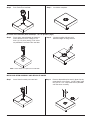
3
Step 4 Push Poke-Thru into floor. Step 5 Installation complete.
For Flush Tile Installation (Start with Steps 1 & 2 on previous page.)
Step 3 Place shims around bottom of flange to
match thickness of tile. Flange is 1/8"
thick. (2) 1/8" shims and (2) 1/16" shims
are provided. Push Poke-Thru into floor.
Step 4 Use grout and/or silicone caulk
between edges of flange and tile.
NOTE: If more shims are required, use Cat. No 6TS.
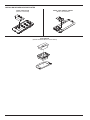
Step 1 Insert Stem Assembly into core hole.
INSTALLING STEM ASSEMBLY AND SEPARATE COVER
Step 2 Remove disposable plate and (2) plate clips by
removing the 8-32 screws. Install Flange using
the (2) 8-32 x 1/2" Cap Head screws provided
with the cover assembly.

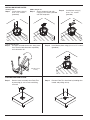
4
Step 1 Remove cover assembly from Poke Thru
by removing (2) 8-32 screws and lifting
cover off.
1.5 Gang Data/AV Plates
Step 1 Use pliers to bend device tabs along score
lines. Bend in both directions repeatedly
until tab breaks off.
Side walls removed
for clarity
Step 2 Install device plate using (2) 6-32 x 1/2" screws.
(provided)
CONFIGURING FEED PLATES
Step 2 Remove Poke Thru from floor by bending tabs
inward and pulling unit up.
Half Gang Plates
Step 1 Install plates using (2)
6-32 x 1/2" screws.
(provided)
I
NSTALLING DEVICE PLATES
NEMA 1 Gang Device
Step 1 Screw receptacle into tabs
using (2) 6-32 screws provided
w
ith the receptacle.
Step 2 Install plates using (2)
6-32 x 1/2" screws.
(provided)

5
Step 3 Remove (2) 8-32 screws and pull off Feed
P
late or housing.
Step 4 Use (2) 8-32 screws to install new Feed Plate
o
r housing
CAUTION: To maintain fire classification, Feed Plates must
be installed.
CAUTION: To maintain fire classification, Feed Plates must
be installed.
Step 3 Slide wire tunnel out of remaining Feed
Housing.
Step 4 Rotate center housing and reattach with
(2) 8-32 screws.
180º
WIRE TUNNEL REMOVAL
Step 1 Remove Feed Housing from center and side
without J-box.
Step 2 Pull wires out of wire tunnel.
Step 5 Reattach side Feed Housing and feed plate with (4) 8-32 screws.
CAUTION: To maintain fire classification, Feed Plates must be installed.

6
INSTALLING DEVICES IN DEVICE PLATES
6TRAC, 6SER, 6ACT8A
(Devices not included)
6MAAP, 6AAP, 6MAAP2A, 68MAAP
(Devices not included)
682A, 6MAAP2A
(Includes 2A bezels. Devices not included)

7
Evolution Series Poke-Thru Devices are UL Listed and Classified to U.S. and Canadian safety standards to the
following conditions:
The 6STC Poke-Thru Stem with the 6CTC or 6CT Service Head Fitting, and the 6ATCP, 6ATP, 6ATCPAV 6ATPAV, 6ATC or
6AT factory assembled Poke-Thru devices are for use with 1-, 1 1/2 -, or 2- hour rated unprotected reinforced concrete floors and
1-, 1 1/2 -, or 2- hour rated floors employing unprotected steel floor units and concrete topping (D900 Series Designs), or concrete
floors with suspended ceilings. (Fire resistive designs with suspended ceilings should have provisions for accessibility in the ceiling
area below the Poke-Thru fittings).
T
he assembled Poke-Thru stem and service fitting will not reduce the ratings of the floor assembly when the thickness and type of
concrete (required for the specific rating) are within the specified limits and the fittings are installed as specified:
1. Spacing – Minimum of 2' [610mm] OC and not more than one unit per 65 sq. ft. [6 sq. m] of floor area in each span.
2. Concrete – Minimum thickness of structural concrete topping of 2 1/4" [57mm] over metal deck or a minimum 3" [76mm]
thick reinforced concrete slab. Unit weight of concrete to be 110 to 155 pcf.
3. Installation – Mounted in a 6" [152mm] diameter hole in concrete per installation instructions accompanying the fittings.
For use with power circuits, data and/or audio/visual cables as tabulated below:
The “TC” suffix letters indicate that the device may be installed on tile or carpet covered concrete floors. The “T” suffix
letter indicates that the device is intended to be installed on a concrete floor, embedded into the tile covering.
Max Copper .0154 sq. in. .0387 sq. in.
X-Section [9.9mm
2
] [24.97mm
2
]
Max # (3) 12 AWG (12) 14 AWG
Conductors
OUTER CENTER
CHANNELS CHANNEL
COPPER CROSS-SECTION
Size Solid
#24 .00032 sq. in. [.20645mm
2
]
#22 .00050 sq. in. [.32258mm
2
]
#14 .00323 sq. in. [2.08386mm
2
]
#12 .00512 sq. in. [3.30321mm
2
]
#10 .00815 sq. in. [5.25805mm
2
]
#8 .01296 sq. in. [8.36127mm
2
]
Copper Cross Sectional Area
of Commonly Used Conductors
NOTE: Use above values for solid or stranded conductors.
NOTE: When using conductor sizes other than listed above, the aggregate cross-sectional area of
the copper conductors shall not exceed the cross-sectional areas listed.
CAUTION: Receptacle supplied with this Poke-Thru is not suitable for direct field wiring.
Contact manufacturer for replacement. Field modifications will void UL Listing
and Classification. Replacement receptacle is limited to this manufacturers'
Catalog No 68REC.

WIREMOLD
U.S. and International:
60 Woodlawn Street • West Hartford, CT 06110
1-800-621-0049 • FAX 860-232-2062 • Outside U.S.: 860-233-6251
Canada:
570 Applewood Crescent • Vaughan, Ontario L4K 4B4
1-800-723-5175 • FAX 905-738-9721
1 007 154 R2 0510
© Copyright 2010 Legrand/Wiremold All Rights Reserved
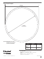
C
arpet Cutout
6 1/2" [166mm]
Carpet Cutout Template
Core Hole
(See chart below for
Core Hole dimensions.)
Covered Floors 6" [152mm] 6 1/8" [156mm]
(Carpet, Tile or
Wood)
Bare Concrete 6 1/16" [154mm] 6 1/8" [156mm]
or Terrazzo
FLOOR CORE CORE
TYPE SIZE (Min.) SIZE (Max.)
CAUTION: When printing copies of this
template please be sure template
is scaled correctly and is the
correct size once it is printed.
-
 1
1
-
 2
2
-
 3
3
-
 4
4
-
 5
5
-
 6
6
-
 7
7
-
 8
8


Legrand Evolution Series 6" Poke-Thru Devices Installation guide
- Category
- Motorcycle Accessories
- Type
- Installation guide
Ask a question and I''ll find the answer in the document
Finding information in a document is now easier with AI
Related papers
-
Legrand 6AT2PSN Installation guide
-
Legrand RC7AFFTCAL-LJB Operating instructions
-
Legrand RC4SHTCAA Operating instructions
-
-
-
Pass and Seymour 880 Series Single-Service Walker Floor Box Cover - 894TC Operating instructions
-
Legrand BK20GB506TRGFI6 Installation guide
-
-
-
Legrand V20GB506 Installation guide
Other documents
-
Hubbell Wiring Device-Kellems CFB11G6FRK Installation guide
-
-
Kozyheat Z42 Owner's manual
-
Escort Passport SRX Owner's manual
-
FMI MM39 User manual
-
-
United States Stove 1600EF User manual
-
NAPOLEON WF 18 User manual
-
-
 Isokern STANDARD 42 Owner's manual
