LG HB6422BRU User manual

Category
Hobs
Type
User manual

LG HB6422BRU gas cooktop offers a range of features for a convenient and efficient cooking experience. It includes adjustable burners for precise heat control, enabling you to cook various dishes with ease. The cooktop's sleek design complements modern kitchens, and its built-in safety features ensure peace of mind while cooking.

LG HB6422BRU gas cooktop offers a range of features for a convenient and efficient cooking experience. It includes adjustable burners for precise heat control, enabling you to cook various dishes with ease. The cooktop's sleek design complements modern kitchens, and its built-in safety features ensure peace of mind while cooking.

Installation and Operating Instructions
Built-In Gas Cooktops
HB6422BRU
P/No.: MFL62060313
www.lg.com
To avoid the risk of accidents or damage to the Gas Cooktops,
it is essential to read these operating instructions
before it is installed or used for the rst time.
And please keep this manual for later reference.
Contents
2
Introduction ................................................................................. 3
1. Instructions for safe and proper use ...................................... 3
Instructions for the installer ...................................................... 5
2. Positioning of the hob ............................................................ 5
3. Electrical connection .............................................................. 7
4. Gas connection ...................................................................... 8
5. Adaptation to different types of gas ...................................... 10
6. Final operations ................................................................... 13
Instructions for the user .......................................................... 15
7. Using the hob ....................................................................... 15
8. Cleaning and maintenance .................................................. 17
These instructions are valid only for end user countries whose
identification symbols appear on the cover of this manual.
INSTRUCTIONS FOR THE INSTALLER: these are for the
authorised person who must carry out a suitable check of the gas
system, install the appliance, set it functioning and carry out an
inspection test.
INSTRUCTIONS FOR THE USER: these contain user advice,
description of the commands and the correct procedures for
cleaning and maintenance of the appliance.
3
Introduction
1. Instructions for safe and proper use
This manual is an integral part of the appliance and therefore must
be kept in its entirety and in an accessible place for the whole
working life of the cooking hob. We advise reading this manual and
all the instructions therein before using the cooking hob. Also keep
the series of nozzles supplied. Installation
must be carried out by qualified personnel in accordance with the
regulations in force. This appliance is intended for domestic uses
and conforms to current regulations in force. The appliance has
been built to carry out the following functions: Cooking and
heating-up of food. All other uses are considered improper.
The manufacturer declines all responsibility for improper use.
Do not leave the packing in the home environment. Separate the
various waste materials and take them to the nearest special
garbage collection centre.
It is obligatory for the electrical system to be grounded according to
the methods required by safety rules.
The plug to be connected to the power cable and the socket must
be the same type and must conform to current regulations.
Never unplug by pulling on the cable.
Immediately after installation carry out a brief inspection test of
the cooking hob, following the instructions below. Should the
appliance not function, disconnect it from the supply and call the
nearest technical assistance centre.
Never attempt to repair the appliance.
Always check that the control knobs are in the position
“ZERO”(OFF) when you finish using the hob.
Introduction
The identification plate, with technical data, serial number and
marking is clearly visible under the casing.
The plate on the casing must not be removed.
Before connecting the device, make sure that it has been regulated for
the type of gas that will feed it, checking the label under the casing.
Do not put pans without perfectly smooth and flat bottoms on the
cooking hob grids.
Do not use recipients or griddle plates that extend beyond the
external perimeter of the hob.
The hob is to be used by adults only. Do not let unsupervised
children play with the hob.
This appliance is designed for cooking food and it shall not be used
as a space heater.
Do not spray aerosols in the vicinity of this appliance while it is in operation.
The manufacturer declines all responsibility for damage to persons or things
caused by non-observance of the above prescriptions or by interference with
any part of the appliance or by the use of non-original spares.
THIS APPLIANCE IS MARKED ACCORDING TO EUROPEAN DIRECTIVE 2002/96/
EC ON WASTE ELECTRICAL AND ELECTRONIC EQUIPMENT (WEEE). THIS
GUIDELINE IS THE FRAME OF EUROPEAN-WIDE VALIDITY OF RETURN AND
RECYCLING ON WASTE ELECTRICAL AND ELECTRONIC EQUIPMENT.
DO NOT USE OR STORE FLAMMABLE MATERIALS IN THE
APPLIANCE STORAGE DRAWER OR NEAR THIS APPLIANCE.
DO NOT MODIFY THIS APPLIANCE
4
5
Instructions for the installer
2. POSITIONING OF HOB
The following operation requires building and/or carpentry work so
must be carried out by a competent tradesman.
Installation can be carried out on various materials such as
masonry, metal, solid wood or plastic laminated wood as long as
they are heat resistant (T 90°C).
Never use silicone or other insulating products when installing the
appliance; use only the rubber gasket provided.
2.1. Attachment to support structure
Create an opening with the dimensions shown in the figure in the
top surface of the counter, keeping a minimum distance of 50 mm
from the rear border. This appliance can therefore be mounted
against walls higher than the work surface on condition that a
certain distance “X” be kept between the appliance and the wall as
shown in the figure so as to avoid damage from overheating.
Make sure there is a minimum of 750 mm between the hot plate
flames and any shelf that may be installed directly above them.
Instructions for the installer
Accurately position the gasket provided all around the outer edge of
the hole in the top surface as shown in the figures below, pressing it
down so as to make it adhere properly. For measurements, refer to
the figure depending on the hob model to be installed, bearing in
mind that in both models the front and rear sides must skim the hole.
Secure the hob to the counter with brackets A (supplied). Carefully
trim any excess from border B of the gasket. The distances in the
following drawing refer to the hole on the inner side of the gasket.
In case of installation on a hollow compartment with doors, a
separating panel has to be placed under the hob. Keep a minimum
distance of 10 mm between the bottom of the unit and the panel
surface. The panel has to be easily removable to allow access in
the event of technical service.
6
7
3. Electrical connection
Make sure that the voltage and capacity of the power line conform
to the data shown on the plate located under the casing. Do not
remove this plate for any reason.
The plug on the end of the supply cable and the wall socket must
be the same type and conform to the current electrical system
regulations. Check that the power line is adequately grounded.
On the power line, install an omnipolar cut-off device with contact
cut-off distance greater than or equal to 3 mm, located in an easily
accessible position near the unit.
Do not use reducers, adapters or shunts.
If the power cable is replaced, the wire section on the new cable
must not be less than 1.5 mm
2
(3 x 1.5 cable), keeping in mind
that the end to be connected to the hob must have the ground
wire (yellow-green) longer by at least 20 mm. Use only
H05V2V2-F cable or similar which has a maximum temperature
of 90°C. Any replacement needed should be carried out by a
specialised technician who should make the mains connections
according to the following diagram.
L = brown
N = blue
= yellow-green
The manufacturer will not be liable for any damage to persons or
property caused by non-observance of the above instructions or
deriving from the tampering of even a single part of the hob.
Instructions for the installer
4. GAS CONNECTION
Connection to the gas mains may be made with a rigid copper pipe
or with a flexible pipe and conforming to the provisions defined by
standard regulations in force.
To facilitate connection, fitting A on the rear of the appliance may be
adjusted laterally. For this purpose, loosen hexagon nut B, turn
fitting A to the desired position, and retighten hexagon nut B
(tightness is ensured by a biconical brass ring). Use a soapy
solution to check for proper tightness. Never use a free flame.
The hob has been inspected for G20 (2H) natural gas at a pressure
of 20 mbar. For use with other types of gases, see Section “5.
ADAPTATION TO DIFFERENT TYPES OF GAS”. The gas intake
fitting is
1
/2 gas external threaded (ISO 228-1).
8
The flexible pipe has to be installed so that pipe length does not
exceed 1.5 meters of maximum extension. Make sure that the pipes
do not touch any moving parts or become damaged.
Connection with rigid copper pipe:
the connection to the gas mains must
not provoke stress of any kind on the
hob.
Connection may be made by using
biconical adapter D with insertion of
gasket C (supplied).
Connection with flexible pipe: use
only flexible pipes conforming to
standard regulations in force, inserting
gasket C (supplied) between fitting A
and flexible pipe E.
9
4.1 Connection to LPG
Use a pressure regulator and make the connection to the tank
according to the provisions of standards regulations in force. Make
sure that feed pressure conforms to the levels shown in the table in
paragraph “5.2 Regulation for LPG”.
4.2 Ventilation of rooms
The hob may be installed only in rooms with permanent ventilation,
as required by standards regulations in force. The room in which
the hob is installed must have sufficient air flow to satisfy the
requirements of normal gas combustion and of necessary air
exchange in the room. The air intakes, protected by screens, must
be appropriately sized (regulations in force) and placed so as not to
be blocked in any way. The room where the oven is installed should
be suitably ventilated to avoid overheating or excess humidity
produced by cooking, and in the case of lengthy use a window
should be opened or the speed of any ventilators should be
increased.
4.3 Discharge of combustion products
Discharge of combustion products must be guaranteed by means of
hoods connected to a natural draught flue with certain efficiency, or
by means of forced aspiration.
An efficient aspiration system requires careful planning by a
specialist capable of installing it, respecting the positions and
distances prescribed by standards. After installation, the installer
must issue a certificate of conformity.
5.
ADAPTATION TO DIFFERENT TYPES OF GAS
Before performing any cleaning or maintenance work, detach
the appliance from the electrical socket.
The hob has been inspected for G20 (2H) natural gas at a
pressure of 20 mbar. For functioning with other types of gas the
nozzles must be replaced and the primary air adjusted.
To replace the nozzles and regulate the burners, you have to
remove the top as described in the following paragraph.
5.1 Removing the hob
1. Remove all the knobs, the grids, the burner caps and the flame-
caps;
2. remove the screws and the nuts A that secure the burner
supports;
3. remove plates B;
4. lift the hob from its seat;
5. replace the burner nozzles in accordance with the reference gas
chart;
6. regulate the primary air as described in paragraph “5.2
Regulation for LPG”.
10
Instructions for the installer
5.2 Regulation for LPG
Loosen screw A and push support B all the way. Use a double head
wrench to remove nozzle C and assemble the suitable one,
following the instructions indicated in the reference charts, with
respect to the type of gas to use. The screwing torque of the nozzle
should never exceed 3 Nm. Reposition support B so that nozzle C
is covered perfectly.
Move the Venturi tube D to regulate the air flow until distance "X" is
reached indicated in the chart in paragraph "5.4 Regulation of
primary air” and then secure the tube by means of screw A. After
the regulations have been carried out, restore the seals with sealing
wax or equivalent material.
11
(*) By-pass value for valveless appliances.
Instructions for the installer
5.3 Regulation for natural gas
The hob has been inspected for G20 (2H) natural gas at a pressure
of 20 mbar. To allow the unit to work with this type of gas, perform
the same operations described in paragraph “5.2 Regulation for
LPG”, but choose the nozzles and regulate the primary air for
natural gas, as shown in the following table and in paragraph "5.4
Regulation of primary air”. After the regulations have been carried
out, restore the seals with sealing wax or equivalent material.
5.4 Regulation of primary air
Referred to distance “X” in mm.
12
To identify the burners on your hob, refer to the drawings in point
“6.3 Arrangement of burners on hob “
6. Final operations
Having carried out the above adjustments, reassemble the
appliance following, backwards, the instructions in paragraph “5.1
Removing the hob”.
6.1 Regulation of minimum for natural gas
Replace the components on the burner and slide
the knobs on the gas tap pins.
Light the burner and set it at minimum position.
Remove the knob and turn the regulation screw
inside or next to the gas tap pin (depending on the
model) until you get a suitable minimum flame.
Replace the knob and check burner flame stability:
(rapidly turning the knob from maximum to
minimum position, the flame should not go out).
6.2 Regulation of minimum for LPG
To regulate the minimum for LPG, completely tighten (clockwise) the
screw inside or next to the gas tap pin (depending on the model).
The diameters of the by-passes for each burner are given in table
“5.2 Regulation for LPG”.
After having regulated the device with gas other than the one
tested, replace the label located on the guard with the one that
corresponds to the new gas. The label is inside the bag that
contains the nozzles provided.
13
Instructions for the installer
6.3 Arrangement of burners on hob
6.4 Lubrication of gas taps
After a while, the gas tap may become hard to turn or lock. If this
happens, it has to be cleaned inside and re-greased.
This must be done by a qualified technician.
14
BURNERS
1. Auxiliary
2. Semi-rapid
3. Rapid
4. Rapid
5. Ultra rapid
7. Using the hob
Before turning on the burners, make sure that the burner rings,
caps and grids have been fitted correctly.
In the Wok burner, notch A must be aligned with pin B.
Grid C provided is intended for use with woks (Chinese pans).
Adapter D comes only with open grids models and is intended
for use with small sized vessels.
Some models do not feature all accessories.
7.1 Ignition of the burners
For each knob the corresponding burner is indicated. The device is
fit with electronic ignition. Simply press and simultaneously turn the
knob counter-clockwise on the low point flame symbol, until the
burner is ignited. Concerning models with valves, push the knob for
approximately 2 seconds in order to keep the flame burning and to
activate the safety device. The burner might go off when the knob is
released. In this case repeat the aforesaid operation keeping the
knob pressed for more than 2 seconds.
Should the burners go off accidentally in the models with valves,
a safety device will trip after approximately 20 seconds to block
the gas outlet even if the tap is open.
15
Instructions for the user
7.2 Practical advice for using the burners
For better burner performance and minimum gas consumption, flat
bottomed, even recipients must be used, with covers and proportional
in size to the burners (see paragraph “7.3 Diameter of containers”).
To avoid overcooking or damage to the surface top while cooking, all
recipients or griddles must be positioned within the cooking hob
perimeter and must be a minimum distance of 3-4 cm from the knobs.
7.3 Diameter of containers
(*) Burner Ø min. and max. (in cm)
1 Auxiliary 12-14
2 Semi-rapid 16-24
3 Rapid (3) 18-26
4 Rapid (4) 22-26
5 Ultra rapid 22-26
(*) For burner reference numbers, see page 14.
7.4 Using a griddle plate
A few precautions are necessary if you wish to use a griddle plate:
leave a gap of at least 160 mm between the edge of the griddle plate and the
side wall;
if one of the burners close to the wooden rear wall is of triple flame type,
leave a gap of at least 160 mm between this wall and the edge of the griddle
plate;
do not allow the burner flames to extend beyond the edge of the griddle plate;
operate the burners underneath the griddle plate for 10 minutes at maximum
power, then turn them down to the minimum setting. Never use the griddle
plate for more than 45 minutes.
16
17
8. Cleaning and maintenance
Never use a steam jet to clean the appliance.
Before any intervention, disconnect the power supply of the
device.
8.1 Cleaning
Clean the cooking top regularly every time you use it, obviously
after it has cooled.
8.1.1 Regular daily cleaning of the hob
In order to clean and preserve the surface, always use specific
products only, which do not contain abrasive substances or
chlorine-based acid substances.
How to use: pour the product on a damp cloth and wipe the
surface, rinse thoroughly and dry with a soft cloth or deerskin.
8.1.2 Food stains or residues
Do not use metallic sponges or sharp scrapers: they will
damage the surface.
Use normal non-abrasive products and remove spots or
residuals with non-scratch sponges or, if need be, with wood or
plastic utensils.
Rinse thoroughly and dry with a soft cloth or deerskin.
18
8.2 Cleaning of cooking hob components
CAUTION: do not wash these components in a dishwasher. In
normal use of the hob, the stainless steel burner caps and pan-
stands tend to be burnished by the high temperature. Clean
these parts using very fine abrasive sponges or similar
commercial products. Then use a specific paste polish to
restore the steel’s shine. Your local authorised after-sales
technician is able to supply professional products for appliance
cleaning and care.
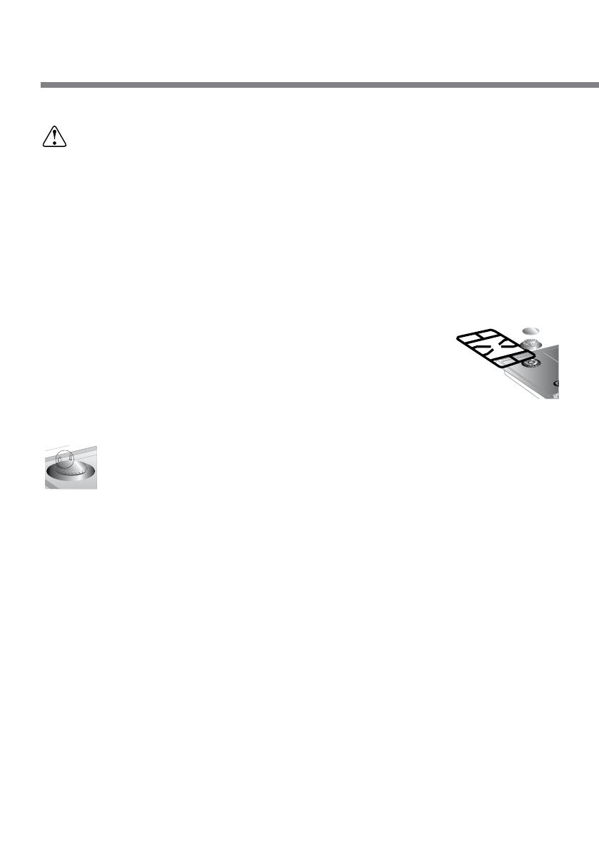
Grids, caps, flame cap crowns and burners can be
removed for ease of cleaning. Wash them in warm
water using a non-abrasive detergent, taking care to
remove all tough spots. Before remounting, allow the
components to fully dry out.
8.2.1 Ignition plugs and safety devices
For good functioning of the lighting ignition plugs and the
safety devices, keep them very clean.
Check frequently and clean with a damp cloth when
necessary.
8.2.2 The cover
Clean the glass or steel cover, where mounted, with warm water.
Never use abrasive sponges or detergents. To clean the rear part of
the cooktop, remove the cover by lifting out.
When finished cleaning, refit the cover making sure to insert it
correctly.
Before lifting up the cover, dry out properly.
Never lower the cover when burners or electric elements are
on or still hot.
Instructions for the user
Printed in Italy
  • Page 1 1
  • Page 2 2
  • Page 3 3
  • Page 4 4
  • Page 5 5
  • Page 6 6
  • Page 7 7
  • Page 8 8
  • Page 9 9
  • Page 10 10
  • Page 11 11
  • Page 12 12
  • Page 13 13
  • Page 14 14
  • Page 15 15
  • Page 16 16
  • Page 17 17
  • Page 18 18
  • Page 19 19
  • Page 20 20

LG HB6422BRU User manual

Category
Hobs
Type
User manual

LG HB6422BRU gas cooktop offers a range of features for a convenient and efficient cooking experience. It includes adjustable burners for precise heat control, enabling you to cook various dishes with ease. The cooktop's sleek design complements modern kitchens, and its built-in safety features ensure peace of mind while cooking.

Ask a question and I''ll find the answer in the document

Finding information in a document is now easier with AI