
RabbitCore RCM4100
C-Programmable Core Module
User’s Manual
019–0153 • 090508–G

RabbitCore RCM4100
Digi International Inc.
www.rabbit.com
RabbitCore RCM4100 User’s Manual
Part Number 019-0153 • 090508–G • Printed in U.S.A.
©2006–2009 Digi International Inc. • All rights reserved.
Digi International reserves the right to make changes and
improvements to its products without providing notice.
Trademarks
Rabbit and Dynamic C are registered trademarks of Digi International Inc.
Rabbit 4000 and RabbitCore are trademarks of Digi International Inc.
No part of the contents of this manual may be reproduced or transmitted in any form or by any means
without the express written permission of Digi International.
Permission is granted to make one or more copies as long as the copyright page contained therein is
included. These copies of the manuals may not be let or sold for any reason without the express written
permission of Digi International.
The latest revision of this manual is available on the Rabbit Web site, www.rabbit.com,
for free, unregistered download.

User’s Manual
TABLE OF CONTENTS
Chapter 1. Introduction 1
1.1 RCM4100 Features...............................................................................................................................2
1.2 Advantages of the RCM4100 ...............................................................................................................4
1.3 Development and Evaluation Tools......................................................................................................5
1.3.1 RCM4110 Development Kit.........................................................................................................5
1.3.2 RCM4100 Analog Development Kit ............................................................................................6
1.3.3 Software........................................................................................................................................6
1.3.4 Online Documentation..................................................................................................................6
Chapter 2. Getting Started 7
2.1 Install Dynamic C.................................................................................................................................7
2.2 Hardware Connections..........................................................................................................................8
2.2.1 Step 1 — Prepare the Prototyping Board for Development..........................................................8
2.2.2 Step 2 — Attach Module to Prototyping Board............................................................................9
2.2.3 Step 3 — Connect Programming Cable......................................................................................10
2.2.4 Step 4 — Connect Power............................................................................................................11
2.3 Run a Sample Program.......................................................................................................................12
2.3.1 Troubleshooting..........................................................................................................................12
2.4 Where Do I Go From Here? ...............................................................................................................13
2.4.1 Technical Support.......................................................................................................................13
Chapter 3. Running Sample Programs 15
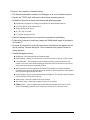
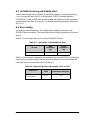
3.1 Introduction.........................................................................................................................................15
3.2 Sample Programs................................................................................................................................16
3.2.1 Serial Communication.................................................................................................................18
3.2.2 A/D Converter Inputs (RCM4100 only).....................................................................................21
3.2.2.1 Downloading and Uploading Calibration Constants.......................................................... 22
3.2.3 Real-Time Clock.........................................................................................................................24
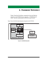
Chapter 4. Hardware Reference 25
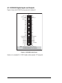
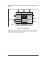
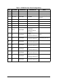
4.1 RCM4100 Digital Inputs and Outputs................................................................................................26
4.1.1 Memory I/O Interface .................................................................................................................32
4.1.2 Other Inputs and Outputs............................................................................................................32
4.2 Serial Communication ........................................................................................................................33
4.2.1 Serial Ports..................................................................................................................................33
4.2.1.1 Using the Serial Ports......................................................................................................... 34
4.2.2 Programming Port.......................................................................................................................35
4.3 Programming Cable............................................................................................................................36
4.3.1 Changing Between Program Mode and Run Mode....................................................................36
4.3.2 Standalone Operation of the RCM4100......................................................................................37
4.4 A/D Converter (RCM4100 only)........................................................................................................38
4.4.1 A/D Converter Power Supply.....................................................................................................40

RabbitCore RCM4100
4.5 Other Hardware..................................................................................................................................41
4.5.1 Clock Doubler ............................................................................................................................41
4.5.2 Spectrum Spreader......................................................................................................................41
4.6 Memory..............................................................................................................................................42
4.6.1 SRAM.........................................................................................................................................42
4.6.2 Flash EPROM.............................................................................................................................42
Chapter 5. Software Reference 43
5.1 More About Dynamic C.....................................................................................................................43
5.2 Dynamic C Function Calls................................................................................................................45
5.2.1 Digital I/O...................................................................................................................................45
5.2.2 Serial Communication Drivers...................................................................................................45
5.2.3 SRAM Use..................................................................................................................................45
5.2.4 Prototyping Board Function Calls..............................................................................................47
5.2.4.1 Board Initialization............................................................................................................ 47
5.2.4.2 Alerts.................................................................................................................................. 48
5.2.5 Analog Inputs (RCM4100 only).................................................................................................49
5.3 Upgrading Dynamic C .......................................................................................................................66
5.3.1 Add-On Modules........................................................................................................................66
Appendix A. RCM4100 Specifications 67
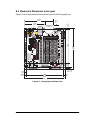
A.1 Electrical and Mechanical Characteristics ........................................................................................68
A.1.1 A/D Converter...........................................................................................................................72
A.1.2 Headers......................................................................................................................................73
A.2 Rabbit 4000 DC Characteristics........................................................................................................74
A.3 I/O Buffer Sourcing and Sinking Limit.............................................................................................75
A.4 Bus Loading ......................................................................................................................................75
A.5 Jumper Configurations ......................................................................................................................78
A.6 Conformal Coating............................................................................................................................80
Appendix B. Prototyping Board 81
B.1 Introduction .......................................................................................................................................82
B.1.1 Prototyping Board Features.......................................................................................................83
B.2 Mechanical Dimensions and Layout.................................................................................................85
B.3 Power Supply.....................................................................................................................................86
B.4 Using the Prototyping Board.............................................................................................................87
B.4.1 Adding Other Components........................................................................................................89
B.4.2 Measuring Current Draw...........................................................................................................89
B.4.3 Analog Features (RCM4100 only) ............................................................................................90
B.4.3.1 A/D Converter Inputs........................................................................................................ 90
B.4.3.2 Thermistor Input ............................................................................................................... 92
B.4.3.3 A/D Converter Calibration................................................................................................ 92
B.4.4 Serial Communication ...............................................................................................................93
B.4.4.1 RS-232 .............................................................................................................................. 94
B.5 Prototyping Board Jumper Configurations........................................................................................95
Appendix C. Power Supply 99
C.1 Power Supplies..................................................................................................................................99
C.1.1 Battery Backup ..........................................................................................................................99
C.1.2 Battery-Backup Circuit............................................................................................................100
C.1.3 Reset Generator........................................................................................................................100
Index 103
Schematics 107

User’s Manual 1
1. INTRODUCTION
The RCM4100 series is the first of the next-generation core
modules that take advantage of new Rabbit
®
4000 features such
as hardware DMA, clock speeds of up to 60 MHz, I/O lines
shared with up to six serial ports and four levels of alternate pin
functions that include variable-phase PWM, auxiliary I/O,
quadrature decoder, and input capture. Coupled with more than
500 new opcode instructions that help to reduce code size and
improve processing speed, this equates to a core module that is
fast, efficient, and the ideal solution for a wide range of embed-
ded applications.
The Development Kit has the essentials that you need to design
your own microprocessor-based system, and includes a com-
plete Dynamic C software development system. This Develop-
ment Kit also contains a Prototyping Board that will allow you
to evaluate the RCM4100 series and to prototype circuits that
interface to the RCM4100 series of modules. You will also be
able to write and test software for these modules.
Throughout this manual, the term RCM4100 series refers to the complete series of
RCM4100 RabbitCore modules unless other production models are referred to specifically.
The RCM4100 has a Rabbit 4000 microprocessor operating at up to 58.98 MHz, static
RAM, flash memory, an 8-channel A/D converter, two clocks (main oscillator and time-
keeping), and the circuitry necessary for reset and management of battery backup of the
Rabbit 4000’s internal real-time clock and the static RAM. One 50-pin header brings out
the Rabbit 4000 I/O bus lines, parallel ports, and serial ports.
The RCM4100 series receives its +3.3 V power from the customer-supplied motherboard
on which it is mounted. The RCM4100 series can interface with all kinds of CMOS-
compatible digital devices through the motherboard.

2 RabbitCore RCM4100
1.1 RCM4100 Features
• Small size: 1.41" × 1.88" × 0.49"
(36 mm × 48 mm × 12 mm)
• Microprocessor: Rabbit 4000 running
at up to 58.98 MHz
• Up to 40 general-purpose I/O lines configurable with up to four alternate functions
• 3.3 V I/O lines with low-power modes down to 2 kHz
•
Six CMOS-compatible serial ports — f
our ports are configurable as a clocked serial port
(SPI), and two ports are configurable as SDLC/HDLC serial ports.
• Alternate I/O bus can be configured for 8 data lines and 6 address lines (shared with
parallel I/O lines), I/O read/write
• 512K flash memory, 256K data SRAM
• Real-time clock
• Watchdog supervisor

User’s Manual 3
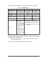
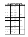
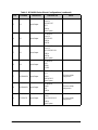
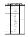
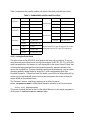
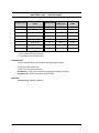
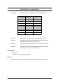
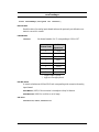
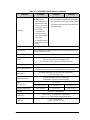
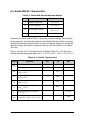
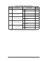
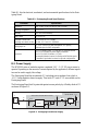
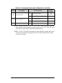
There are three RCM4100 production models. Table 1 summarizes their main features.
The RCM4100 series is programmed over a standard PC USB port through a programming
cable supplied with the Development Kit.
NOTE: The RabbitLink cannot be used to program RabbitCore modules based on the
Rabbit 4000 microprocessor.
Appendix A provides detailed specifications for the RCM4100 series.
Table 1. RCM4100 Features
Feature RCM4100 RCM4110 RCM4120
Microprocessor
Rabbit
®
4000
at 58.98 MHz
Rabbit
®
4000
at 29.49 MHz
Rabbit
®
4000
at 58.98 MHz
Flash Memory 512K
Data SRAM 512K 256K 512K
Fast Program-Execution
SRAM
512K — 512K
A/D Converter 12 bits — —
Serial Ports
6 high-speed, CMOS-
compatible ports:
• all 6 configurable as
asynchronous (with
IrDA), 4 as clocked
serial (SPI), and 2 as
SDLC/HDLC
• 1 asynchronous
clocked serial port
shared with program-
ming port
• 1 clocked serial port
shared with A/D con-
verter
6 high-speed, CMOS-compatible ports:
• all 6 configurable as asynchronous (with IrDA),
4 as clocked serial (SPI), and 2 as SDLC/HDLC
• 1 asynchronous clocked serial port shared with
programming port

4 RabbitCore RCM4100
1.2 Advantages of the RCM4100
• Fast time to market using a fully engineered, “ready-to-run/ready-to-program” micro-
processor core.
• Competitive pricing when compared with the alternative of purchasing and assembling
individual components.
• Easy C-language program development and debugging
• Rabbit Field Utility to download compiled Dynamic C .bin files, and cloning board
options for rapid production loading of programs.
• Generous memory size allows large programs with tens of thousands of lines of code,
and substantial data storage.

User’s Manual 5
1.3 Development and Evaluation Tools
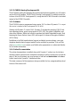
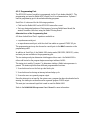
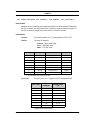
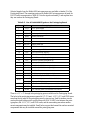
1.3.1 RCM4110 Development Kit
The RCM4110 Development Kit contains the hardware essentials you will need to use
your RCM4110 module. The items in the Development Kit and their use are as follows.
• RCM4110 module.
• Prototyping Board.
• Universal AC adapter, 12 V DC, 1 A (includes Canada/Japan/U.S., Australia/N.Z.,
U.K., and European style plugs). Development Kits sold in North America may contain
an AC adapter with only a North American style plug.
• Programming cable with integrated level-matching circuitry.
•
10-pin header to DB9 serial cable.
• Dynamic C
®
CD-ROM, with complete product documentation on disk.
• Getting Started instructions.
• A bag of accessory parts for use on the Prototyping Board.
• Rabbit 4000 Processor Easy Reference poster.
• Registration card.
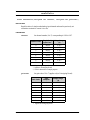
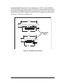
Figure 1. RCM4110 Development Kit
Rabbit and Dynamic C are registered trademarks of Rabbit Semiconductor Inc.
RabbitCore RCM4110
The RCM4110 RabbitCore module features 16-bit memory, allowing you to create a low-cost, low-power,
control solution for your embedded application. These Getting Started instructions included with the Devel-
opment Kit will help you get your RCM4100 up and running so that you can run the sample programs to
explore its capabilities and develop your own applications.
Development Kit Contents
The RCM4110 Development Kit contains the following items:
• RCM4110 module.
• Prototyping Board.
• Universal AC adapter, 12 V DC, 1 A (includes Canada/Japan/U.S., Australia/N.Z., U.K., and European
style plugs). Development Kits sold in North America may contain an AC adapter with only a North
American style plug.
• Programming cable with integrated level-matching circuitry.
• 10-pin header to DB9 serial cable.
• Dynamic C
®
CD-ROM, with complete product documentation on disk.
• Getting Started instructions.
• Plastic and metal standoffs with 4-40 screws and washers.
• A bag of accessory parts for use on the Prototyping
Board.
• Rabbit 4000 Processor Easy Reference poster.
• Registration card.
Visit our online Rabbit store at www.rabbit.com/store/ for
the latest information on peripherals and accessories that
are available for all RCM4100 RabbitCore module models.
Installing Dynamic C
®
Insert the CD from the Development Kit in
your PC’s CD-ROM drive. If the installation
does not auto-start, run the setup.exe pro-
gram in the root directory of the Dynamic C
CD. Install any Dynamic C modules after you
install Dynamic C
.
Getting Started
Instructions
Prototyping Board
Accessory Parts for
Prototyping Board
Serial
Cable
Programming
Cable
D
1
R
1
PWR
DS1
GND
J1
U1
C1
GND
C2
J
P
1
C
3
D
2
J
P
2
C
4
+
3
.
3
V
J2
R
2
BT1
1
S1
RESET
R
X
D
T
X
D
T
X
C
R
X
C
G
N
D
J
4
U
X
2
9
RX81
R
X
8
7
C
X
4
1
RX83
RX11
C
X
3
9
UX30
UX10
UX12
UX14
UX16
RX79
C
X
2
9
C
X
1
7
RX67
U
X
4
5
R
X
8
5
GND
GND
GND
1
R24
R22
R21
R23
CX23
RX77
1
R
2
7
R
2
8
JP25
CX25
RX75
RX73
CX27
DS3
S3S2
DS2
J3
UX49
UX4
UX47
+5 V
GND
+3.3 V
RCM1
U
2
/RST_OUT
/IOWR
VBAT
EXT
PA1
PA3
PA5
PA7
PB1
PB3
PB5
PB7
PC1
PC3
PC5
PC7
PE1
PE3
PE5
PE7
PD1
LN1
PD3
LN3
PD5
LN5
PD7
LN7
VREF
GND
/IORD
/RST_IN
PA0
PA2
PA4
PA6
PB0
PB2
PB4
PB6
PC0
PC2
PC4
PC6
PE0
PE2
PE4
PE6
PD0
LN0
PD2
LN2
PD4
LN4
PD6
LN6
CVT
AGND
J
P
2
4
J
P
2
3
C
1
4
C
1
2
C
1
0
C
8
C
7
C
9
C
1
1
C
1
3
R10
R
8
R
6
R
4
R
3
R
5
R
7
R20
R
1
8
R
1
6
R
1
4
R
1
3
R
1
5
R
1
7
R29
J
P
1
1
J
P
1
5
J
P
1
9
J
P
2
1
J
P
2
2
J
P
2
0
J
P
1
7
J
P
1
3
R19
R9
RX57
RX55
RX97
RX49
U
X
3
3
U
X
3
1
R
X
8
9
UX3
U
X
3
7
U
X
4
2
U
X
4
1
R
X
6
3
R
X
6
5
R
X
6
1
RX59
R
2
6
R25
Q1
C15
C
1
9
C
2
0
U3
C18
C
1
7
JP16
JP6
JP5
JP12
JP4
JP3
JP14
JP8
JP7
JP18
JP9
JP10
C16
L1
C6
C5
A
G
N
D
C
V
T
L
N
6
I
N
L
N
4
I
N
L
N
2
I
N
L
N
0
I
N
V
R
E
F
L
N
7
I
N
L
N
5
I
N
L
N
3
I
N
L
N
1
I
N
A
G
N
D
A
G
N
D
R
1
1
R
1
2
R
X
4
7
RX43
Universal
AC Adapter
with Plugs
C20
L1
C21
R5
R6
R7
R8
R9
R10
R11
R12
R13
C9
C10
C11
C12
C13
C14
C15
C16
RP1
JP6
JP5
R
20
JP4
C3
U4
TP2
J1
R38
R2
R1
U1
C8
C1
U2
C5
C4
R3
U3
R37
R21
U5
C17
C18
C52
C56
R23
R22
U6
JP3
R
41
C6
C7
R4
U9
C53
1
40
41
80
PROG
DIAG

6 RabbitCore RCM4100
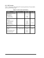
1.3.2 RCM4100 Analog Development Kit
The RCM4100 Analog Development Kit contains the hardware essentials you will need to
use the RCM4100 module. The RCM4100 Analog Development Kit contents are similar
to those of the RCM4110 Development Kit, except that the RCM4100 module is included
instead of the RCM4110 module.
1.3.3 Software
The RCM4100 series is programmed using version 10.01 or later of Dynamic C.
A compat-
ible version is included on the Development Kit CD-ROM.
Starting with Dynamic C version 10.40, Dynamic C includes the popular µC/OS-II real-
time operating system, point-to-point protocol (PPP), FAT file system, RabbitWeb, and
other select libraries. Rabbit also offers for purchase the Rabbit Embedded Security Pack
featuring the Secure Sockets Layer (SSL) and a specific Advanced Encryption Standard
(AES) library.
In addition to the Web-based technical support included at no extra charge, a one-year
telephone-based technical support module is also available for purchase. Visit our Web
site at www.rabbit.com or contact your Rabbit sales representative or authorized distribu-
tor for further information.
1.3.4 Online Documentation
The online documentation is installed along with Dynamic C, and an icon for the docu-
mentation menu is placed on the workstation’s desktop. Double-click this icon to reach the
menu. If the icon is missing, use your browser to find and load
default.htm in the docs
folder, found in the Dynamic C installation folder.
The latest versions of all documents are always available for free, unregistered download
from our Web sites as well.

User’s Manual 7
2. GETTING STARTED
This chapter describes the RCM4100 series in more detail, and
explains how to set up and use the accompanying Prototyping Board.
NOTE: This chapter (and this manual) assume that you have the RCM4100 Development
Kit. If you purchased an RCM4100 module by itself, you will have to adapt the infor-
mation in this chapter and elsewhere to your test and development setup.
2.1 Install Dynamic C
To develop and debug programs for the RCM4100 series (and for all other Rabbit hard-
ware), you must install and use Dynamic C.
If you have not yet installed Dynamic C version 10.01 (or a later version), do so now by
inserting the Dynamic C CD from the RCM4100 Development Kit in your PC’s CD-ROM
drive. If autorun is enabled, the CD installation will begin automatically.
If autorun is disabled or the installation does not start, use the Windows Start | Run menu
or Windows Disk Explorer to launch setup.exe from the root folder of the CD-ROM.
The installation program will guide you through the installation process. Most steps of the
process are self-explanatory.
Dynamic C uses a COM (serial) port to communicate with the target development system.
The installation allows you to choose the COM port that will be used. The default selec-
tion is COM1. You may select any available port for Dynamic C’s use. If you are not cer-
tain which port is available, select COM1. This selection can be changed later within
Dynamic C.
NOTE: The installation utility does not check the selected COM port in any way. Speci-
fying a port in use by another device (mouse, modem, etc.) may lead to a message such
as "could not open serial port" when Dynamic C is started.
Once your installation is complete, you will have up to three new icons on your PC desk-
top. One icon is for Dynamic C, one opens the documentation menu, and the third is for
the Rabbit Field Utility, a tool used to download precompiled software to a target system.
If you have purchased any of the optional Dynamic C modules, install them after installing
Dynamic C. The modules may be installed in any order. You must install the modules in
the same directory where Dynamic C was installed.

8 RabbitCore RCM4100
2.2 Hardware Connections
There are three steps to connecting the Prototyping Board for use with Dynamic C and the
sample programs:
1. Prepare the Prototyping Board for Development.
2. Attach the RCM4100 module to the Prototyping Board.
3. Connect the programming cable between the RCM4100 and the PC.
4. Connect the power supply to the Prototyping Board.
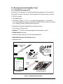
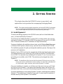
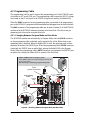
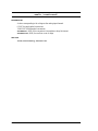
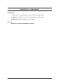
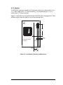
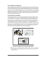
2.2.1 Step 1 — Prepare the Prototyping Board for Development
Snap in four of the plastic standoffs supplied in the bag of accessory parts from the Devel-
opment Kit in the holes at the corners as shown.
Figure 2. Insert Standoffs
D
1
R
1
PWR
DS1
GND
J1
U1
C1
GND
C2
JP
1
C
3
D
2
JP
2
C
4
+
3.3 V
J2
R
2
BT1
1
S1
RESET
R
XD
TX
D
TX
C
R
XC
G
N
D
J4
UX
29
RX81
R
X
87
C
X41
RX83
RX11
C
X
39
UX30
UX10
UX12
UX14
UX16
RX79
C
X
29
C
X17
RX67
U
X45
RX
85
GND
GND
GND
1
R24
R22
R21
R23
CX23
RX77
1
R
27
R
28
JP25
CX25
RX75
RX73
CX27
DS3
S3S2
DS2
J3
UX49
UX4
UX47
+5 V
GND
+3.3 V
RCM1
U
2
/RST_OUT
/IOWR
VBAT
EXT
PA1
PA3
PA5
PA7
PB1
PB3
PB5
PB7
PC1
PC3
PC5
PC7
PE1
PE3
PE5
PE7
PD1
LN1
PD3
LN3
PD5
LN5
PD7
LN7
VREF
GND
/IORD
/RST_IN
PA0
PA2
PA4
PA6
PB0
PB2
PB4
PB6
PC0
PC2
PC4
PC6
PE0
PE2
PE4
PE6
PD0
LN0
PD2
LN2
PD4
LN4
PD6
LN6
CVT
AGND
JP
24
JP
23
C
14
C
12
C
10
C
8
C
7
C
9
C
11
C
13
R10
R
8
R
6
R
4
R
3
R
5
R
7
R20
R
18
R
16
R
14
R
13
R
15
R
17
R29
JP
11
JP
15
JP
19
JP
21
JP22
JP20
JP17
JP
13
R19
R9
RX57
RX55
RX97
RX49
U
X33U
X
31
R
X
89
UX3
U
X
37
U
X
42
U
X
41
R
X
63
R
X
65
R
X
61
RX59
R
26
R25
Q1
C15
C
19
C
20
U3
C18
C
17
JP16
JP6
JP5
JP12
JP4
JP3
JP14
JP8
JP7
JP18
JP9
JP10
C16
L1
C6
C5
AG
N
D
C
V
T
LN
6IN
LN
4IN
LN
2IN
LN
0IN
V
R
E
F
LN
7IN
LN
5IN
LN
3IN
LN
1IN
A
G
N
D
A
G
N
D
R
11
R
12
R
X
47
RX43

User’s Manual 9
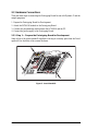
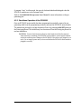
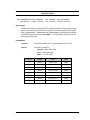
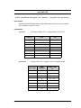
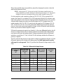
2.2.2 Step 2 — Attach Module to Prototyping Board
Turn the RCM4100 module so that the mounting holes line up with the corresponding
holes on the Prototyping Board. Insert the metal standoffs as shown, secure them from the
bottom using two screws and washers, then insert the module’s header J2 on the bottom
side into socket RCM1 on the Prototyping Board.
Figure 3. Install the Module on the Prototyping Board
NOTE: It is important that you line up the pins on header J2 of the module exactly with
socket RCM1 on the Prototyping Board. The header pins may become bent or damaged
if the pin alignment is offset, and the module will not work. Permanent electrical dam-
age to the module may also result if a misaligned module is powered up.
Press the module’s pins gently into the Prototyping Board socket—press down in the area
above the header pins. For additional integrity, you may secure the RCM4100 to the stand-
offs from the top using the remaining two screws and washers.
D1
R1
PWR
DS1
GND
J1
U1
C1
GND
C2
JP1
C3
D2
JP2
C4
+3.3 V
J2
R2
BT1
1
S1
RESET
RXD TXD
TXC RXC
GND
J4
UX29
RX81
RX87
CX41
RX83
RX11
CX39
UX30
UX10
UX12
UX14
UX16
RX79
CX29
CX17
RX67
UX45
RX85
GND
GND
GND
1
R24
R22
R21
R23
CX23
RX77
1
R27
R28
JP25
CX25
RX75
RX73
CX27
DS3
S3S2
DS2
J3
UX49
UX4
UX47
+5 V
GND
+3.3 V
RCM1
U2
/RST_OUT
/IOWR
VBAT
EXT
PA1
PA3
PA5
PA7
PB1
PB3
PB5
PB7
PC1
PC3
PC5
PC7
PE1
PE3
PE5
PE7
PD1
LN1
PD3
LN3
PD5
LN5
PD7
LN7
VREF
GND
/IORD
/RST_IN
PA0
PA2
PA4
PA6
PB0
PB2
PB4
PB6
PC0
PC2
PC4
PC6
PE0
PE2
PE4
PE6
PD0
LN0
PD2
LN2
PD4
LN4
PD6
LN6
CVT
AGND
JP24
JP23
C14
C12
C10
C8
C7
C9
C11
C13
R10
R8
R6
R4
R3
R5
R7
R20
R18
R16
R14
R13
R15
R17
R29
JP11
JP15
JP19
JP21
JP22
JP20
JP17
JP13
R19
R9
RX57
RX55
RX97
RX49
UX33UX31
RX89
UX3
UX37 UX42
UX41
RX63
RX65
RX61
RX59
R26
R25
Q1
C15
C19 C20
U3
C18
C17
JP16
JP6
JP5
JP12
JP4
JP3
JP14
JP8
JP7
JP18
JP9
JP10
C16
L1
C6
C5
AGND
CVT
LN6IN
LN4IN
LN2IN
LN0IN
VREF
LN7IN
LN5IN
LN3IN
LN1IN
AGND
AGND
R11
R12
RX47
RX43
RCM4100
RCM1
R1
J1
R2
R5
R4
R3
JP1
JP2
JP9
JP6
JP7
JP3
JP5
JP4
C4
C3
C2
L1
C1
R7
R8
R6
R10
R9
U1
U2
R11
C15
RP2
C16
C17
D1
R27
RP1
R15
C23
R17
R16
C21
C14
U6
R19
R18
R22
R23
Y2
C27
U7
C28
R21
JP8
JP10
JP11
JP12
C5
Y1
Q1
C6
C7
C8
C9
C10 C11
U5
C12
C13
R12
C24
R14
C25
C26
C19
C20
U4
U3
C18
R13
C30
C31
C34 C35
C32
C33
C29
C38
C39
C37
C36
Line up mounting
holes with holes
on Prototyping Board.
Insert standoffs
between
mounting holes and
Prototyping Board.

10 RabbitCore RCM4100
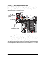
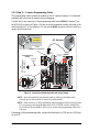
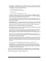
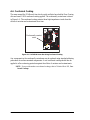
2.2.3 Step 3 — Connect Programming Cable
The programming cable connects the module to the PC running Dynamic C to download
programs and to monitor the module during debugging.
Connect the 10-pin connector of the programming cable labeled
PROG to header J1 on
the RCM4100 as shown in Figure 4. Be sure to orient the marked (usually red) edge of the
cable towards pin 1 of the connector. (Do not use the DIAG connector, which is used for a
normal serial connection.)
Figure 4. Connect Programming Cable and Power Supply
NOTE: Never disconnect the programming cable by pulling on the ribbon cable.
Carefully pull on the connector to remove it from the header.
NOTE: Either a serial or a USB programming cable was supplied with this Development
Kit. If you have a serial programming cable, an RS-232/USB converter (Rabbit Part
No. 20-151-0178) is available to allow you to use the serial programming cable with a
USB port.
Depending on the programming cable, connect the other end to a COM port or a USB port
on your PC.
D1
R1
PWR
DS1
GND
J1
U1
C1
GND
C2
JP1
C3
D2
JP2
C4
+3.3 V
J2
R2
BT1
1
S1
RESET
RXD TXD
TXC RXC
GND
J4
UX29
RX81
RX87
CX41
RX83
RX11
CX39
UX30
UX10
UX12
UX14
UX16
RX79
CX29
CX17
RX67
UX45
RX85
GND
GND
GND
1
R24
R22
R21
R23
CX23
RX77
1
R27
R28
JP25
CX25
RX75
RX73
CX27
DS3
S3S2
DS2
J3
UX49
UX4
UX47
+5 V
GND
+3.3 V
RCM1
U2
/RST_OUT
/IOWR
VBAT
EXT
PA1
PA3
PA5
PA7
PB1
PB3
PB5
PB7
PC1
PC3
PC5
PC7
PE1
PE3
PE5
PE7
PD1
LN1
PD3
LN3
PD5
LN5
PD7
LN7
VREF
GND
/IORD
/RST_IN
PA0
PA2
PA4
PA6
PB0
PB2
PB4
PB6
PC0
PC2
PC4
PC6
PE0
PE2
PE4
PE6
PD0
LN0
PD2
LN2
PD4
LN4
PD6
LN6
CVT
AGND
JP24
JP23
C14
C12
C10
C8
C7
C9
C11
C13
R10
R8
R6
R4
R3
R5
R7
R20
R18
R16
R14
R13
R15
R17
R29
JP11
JP15
JP19
JP21
JP22
JP20
JP17
JP13
R19
R9
RX57
RX55
RX97
RX49
UX33UX31
RX89
UX3
UX37 UX42
UX41
RX63
RX65
RX61
RX59
R26
R25
Q1
C15
C19 C20
U3
C18
C17
JP16
JP6
JP5
JP12
JP4
JP3
JP14
JP8
JP7
JP18
JP9
JP10
C16
L1
C6
C5
AGND
CVT
LN6IN
LN4IN
LN2IN
LN0IN
VREF
LN7IN
LN5IN
LN3IN
LN1IN
AGND
AGND
R11
R12
RX47
RX43
R1
J1
R2
R5
R4
R3
JP1
JP2
JP9
JP6
JP7
JP3
JP5
JP4
C4
C3
C2
L1
C1
R7
R8
R6
R10
R9
U1
U2
R11
C15
RP2
C16
C17
D1
R27
RP1
R15
C23
R17
R16
C21
C14
U6
R19
R18
R22
R23
Y2
C27
U7
C28
R21
JP8
JP10
JP11
JP12
C5
Y1
Q1
C6
C7
C8
C9
C10 C11
U5
C12
C13
R12
C24
R14
C25
C26
C19
C20
U4
U3
C18
R13
C30
C31
C34 C35
C32
C33
C29
C38
C39
C37
C36
RESET
AC Adapter
Remove slot cover,
insert tab into slot
Snap plug into place
2
1
Assemble
AC Adapter
3-pin
power connector
J1
Colored
edge
To
PC COM port
or USB port
PROG
DIAG
Programming
Cable
PROG
J1

User’s Manual 11
If you are using a USB programming cable, your PC should recognize the new USB hard-
ware, and the LEDs in the shrink-wrapped area of the programming cable will flash — if
you get an error message, you will have to install USB drivers. Drivers for Windows XP
are available in the Dynamic C Drivers\Rabbit USB Programming Cable\
WinXP_2K
folder — double-click DPInst.exe to install the USB drivers. Drivers for
other operating systems are available online at www.ftdichip.com/Drivers/VCP.htm.
2.2.4 Step 4 — Connect Power
Once all the other connections have been made, you can connect power to the Prototyping
Board.
If you have the universal AC adapter, prepare the AC adapter for the country where it will
be used by selecting the appropriate plug. Insert the top of the plug assembly into the slot at
the top of the AC adapter as shown in Figure 4, then press down on the plug until it clicks
into place.
Connect the AC adapter to 3-pin header J1 on the Prototyping Board as shown in Figure 4
above. The connector may be attached either way as long as it is not offset to one side—
the center pin of J1 is always connected to the positive terminal, and either edge pin is
ground.
Plug in the AC adapter. The PWR LED on the Prototyping Board next to the power con-
nector at J1 should light up. The RCM4100 and the Prototyping Board are now ready to be
used.
NOTE: A RESET button is provided on the Prototyping Board next to the battery holder
to allow a hardware reset without disconnecting power.
To power down the Prototyping Board, unplug the power connector from J1. You should
disconnect power before making any circuit adjustments in the prototyping area, changing
any connections to the board, or removing the RCM4100 from the Prototyping Board.

12 RabbitCore RCM4100
2.3 Run a Sample Program
Once the RCM4100/RCM4110 is connected as described in the preceding pages, start
Dynamic C by double-clicking on the Dynamic C icon on your desktop or in your
Start
menu.
If you are using a USB port to connect your computer to the RCM4100/RCM4110, click
on the “Communications” tab and verify that
Use USB to Serial Converter is selected to
support the USB programming cable. Click
OK. You may have to determine which COM
port was assigned to the RS-232/USB converter. Open
Control Panel > System > Hard-
ware > Device Manager > Ports
and identify which COM port is used for the USB con-
nection. In Dynamic C, select
Options > Project Options, then select this COM port on
the
Communications tab, then click OK. You may type the COM port number followed by
Enter on your computer keyboard if the COM port number is outside the range on the drop-
down menu.
Now find the file PONG.C, which is in the Dynamic C SAMPLES folder. To run the pro-
gram, open it with the
File menu, compile it using the Compile menu, and then run it by
selecting
Run in the Run menu. The STDIO window will open on your PC and will dis-
play a small square bouncing around in a box.
2.3.1 Troubleshooting
If Dynamic C appears to compile the BIOS successfully, but you then receive a communi-
cation error message when you compile and load a sample program, it is possible that your
PC cannot handle the higher program-loading baud rate. Try changing the maximum
download rate to a slower baud rate as follows.
• Locate the Serial Options dialog in the Dynamic C Options > Project Options >
Communications
menu. Select a slower Max download baud rate.
If a program compiles and loads, but then loses target communication before you can
begin debugging, it is possible that your PC cannot handle the default debugging baud
rate. Try lowering the debugging baud rate as follows.
• Locate the
Serial Options dialog in the Dynamic C Options > Project Options >
Communications
menu. Choose a lower debug baud rate.
If you receive the message
No Rabbit Processor Detected, the programming cable
may be connected to the wrong COM port, a connection may be faulty, or the target sys-
tem may not be powered up. First, check to see that the power LED on the Prototyping
Board is lit and that the jumper across pins 5–6 of header JP10 on the Prototyping Board is
installed. If the LED is lit, check both ends of the programming cable to ensure that it is
firmly plugged into the PC and the programming header on the RCM4100 with the marked
(colored) edge of the programming cable towards pin 1 of the programming header. Ensure
that the module is firmly and correctly installed in its connectors on the Prototyping Board.
If there are no faults with the hardware, select a different COM port within Dynamic C as
explained for the USB port above. Press <Ctrl-Y> to force Dynamic C to recompile the
BIOS. If Dynamic C still reports it is unable to locate the target system, repeat the above
steps for another available COM port. You should receive a
Bios compiled success-
fully
message once this step is completed successfully.

User’s Manual 13
2.4 Where Do I Go From Here?
If the sample program ran fine, you are now ready to go on to the sample programs in the
RCM4100 User’s Manual (click the documentation icon on your PC) and to develop your
own applications. The sample programs
can be easily modified for your own use. The user's
manual also provides complete hardware reference information and software function calls for
the RCM4100 and the Prototyping Board.
For advanced development topics, refer to the Dynamic C User’s Manual, also in the
online documentation set, which is on the Dynamic C CD in a docs folder..
2.4.1 Technical Support
NOTE: If you purchased your RCM4100 through a distributor or through a Rabbit partner,
contact the distributor or partner first for technical support.
If there are any problems at this point:
• Use the Dynamic C
Help menu to get further assistance with Dynamic C.
• Check the Rabbit Technical Bulletin Board and forums at www.rabbit.com/support/bb/
and at www.rabbit.com/forums/.
• Use the Technical Support e-mail form at www.rabbit.com/support/.

14 RabbitCore RCM4100

User’s Manual 15
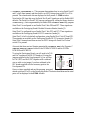
3. RUNNING SAMPLE PROGRAMS
To develop and debug programs for the RCM4100 series (and
for all other Rabbit hardware), you must install and use
Dynamic C. This chapter provides a tour of its major features
with respect to the RCM4100 series.
3.1 Introduction
To help familiarize you with the RCM4100 series of modules, Dynamic C includes several
sample programs. Loading, executing and studying these programs will give you a solid
hands-on overview of the RCM4100 series’ capabilities, as well as a quick start with
Dynamic C as an application development tool.
NOTE:
The sample programs assume that you have at least an elementary grasp of ANSI C.
If you do not, see the introductory pages of the Dynamic C User’s Manual for a sug-
gested reading list.
In order to run the sample programs discussed in this chapter and elsewhere in this manual,
1. Your module must be plugged in to the Prototyping Board as described in Chapter 2,
“Getting Started.”
2. Dynamic C must be installed and running on your PC.
3. The programming cable must connect the programming header on the module to your
PC.
4. Power must be applied to the module through the Prototyping Board.
Refer to Chapter 2, “Getting Started,” if you need further information on these steps.
To run a sample program, open it with the
File menu (if it is not still open), then compile
and run it by pressing F9.
Each sample program has comments that describe the purpose and function of the pro-
gram. Follow the instructions at the beginning of the sample program.
More complete information on Dynamic C is provided in the Dynamic C User’s Manual.

16 RabbitCore RCM4100
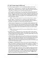
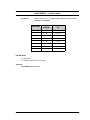
3.2 Sample Programs
Of the many sample programs included with Dynamic C, several are specific to the
RCM4100 series of modules. These programs will be found in the SAMPLES\RCM4100
folder.
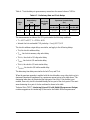
• CONTROLLED.C—Demonstrates use of the digital outputs by having you turn LEDs
DS2 and DS3 on the Prototyping Board on or off from the STDIO window on your PC.
Parallel Port B bit 2 = LED DS2
Parallel Port B bit 3 = LED DS3
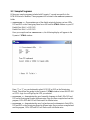
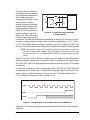
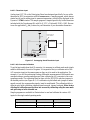
Once you compile and run CONTROLLED.C, the following display will appear in the
Dynamic C STDIO window.
Press “2” or “3” on your keyboard to select LED DS2 or DS3 on the Prototyping
Board. Then follow the prompt in the Dynamic C
STDIO window to turn the LED ON
or OFF. A logic low will light up the LED you selected.
• FLASHLED1.C—demonstrates the use of assembly language to flash LEDs DS2 and
DS3 on the Prototyping Board at different rates. Once you have compiled and run this
program, LEDs DS2 and DS3 will flash on/off at different rates.
•
FLASHLED2.C—demonstrates the use of cofunctions and costatements to flash LEDs
DS2 and DS3 on the Prototyping Board at different rates. Once you have compiled and
run this program, LEDs DS2 and DS3 will flash on/off at different rates.
Page is loading ...
Page is loading ...
Page is loading ...
Page is loading ...
Page is loading ...
Page is loading ...
Page is loading ...
Page is loading ...
Page is loading ...
Page is loading ...
Page is loading ...
Page is loading ...
Page is loading ...
Page is loading ...
Page is loading ...
Page is loading ...
Page is loading ...
Page is loading ...
Page is loading ...
Page is loading ...
Page is loading ...
Page is loading ...
Page is loading ...
Page is loading ...
Page is loading ...
Page is loading ...
Page is loading ...
Page is loading ...
Page is loading ...
Page is loading ...
Page is loading ...
Page is loading ...
Page is loading ...
Page is loading ...
Page is loading ...
Page is loading ...
Page is loading ...
Page is loading ...
Page is loading ...
Page is loading ...
Page is loading ...
Page is loading ...
Page is loading ...
Page is loading ...
Page is loading ...
Page is loading ...
Page is loading ...
Page is loading ...
Page is loading ...
Page is loading ...
Page is loading ...
Page is loading ...
Page is loading ...
Page is loading ...
Page is loading ...
Page is loading ...
Page is loading ...
Page is loading ...
Page is loading ...
Page is loading ...
Page is loading ...
Page is loading ...
Page is loading ...
Page is loading ...
Page is loading ...
Page is loading ...
Page is loading ...
Page is loading ...
Page is loading ...
Page is loading ...
Page is loading ...
Page is loading ...
Page is loading ...
Page is loading ...
Page is loading ...
Page is loading ...
Page is loading ...
Page is loading ...
Page is loading ...
Page is loading ...
Page is loading ...
Page is loading ...
Page is loading ...
Page is loading ...
Page is loading ...
Page is loading ...
Page is loading ...
Page is loading ...
Page is loading ...
Page is loading ...
Page is loading ...
Page is loading ...
-
 1
1
-
 2
2
-
 3
3
-
 4
4
-
 5
5
-
 6
6
-
 7
7
-
 8
8
-
 9
9
-
 10
10
-
 11
11
-
 12
12
-
 13
13
-
 14
14
-
 15
15
-
 16
16
-
 17
17
-
 18
18
-
 19
19
-
 20
20
-
 21
21
-
 22
22
-
 23
23
-
 24
24
-
 25
25
-
 26
26
-
 27
27
-
 28
28
-
 29
29
-
 30
30
-
 31
31
-
 32
32
-
 33
33
-
 34
34
-
 35
35
-
 36
36
-
 37
37
-
 38
38
-
 39
39
-
 40
40
-
 41
41
-
 42
42
-
 43
43
-
 44
44
-
 45
45
-
 46
46
-
 47
47
-
 48
48
-
 49
49
-
 50
50
-
 51
51
-
 52
52
-
 53
53
-
 54
54
-
 55
55
-
 56
56
-
 57
57
-
 58
58
-
 59
59
-
 60
60
-
 61
61
-
 62
62
-
 63
63
-
 64
64
-
 65
65
-
 66
66
-
 67
67
-
 68
68
-
 69
69
-
 70
70
-
 71
71
-
 72
72
-
 73
73
-
 74
74
-
 75
75
-
 76
76
-
 77
77
-
 78
78
-
 79
79
-
 80
80
-
 81
81
-
 82
82
-
 83
83
-
 84
84
-
 85
85
-
 86
86
-
 87
87
-
 88
88
-
 89
89
-
 90
90
-
 91
91
-
 92
92
-
 93
93
-
 94
94
-
 95
95
-
 96
96
-
 97
97
-
 98
98
-
 99
99
-
 100
100
-
 101
101
-
 102
102
-
 103
103
-
 104
104
-
 105
105
-
 106
106
-
 107
107
-
 108
108
-
 109
109
-
 110
110
-
 111
111
-
 112
112


Ask a question and I''ll find the answer in the document
Finding information in a document is now easier with AI
Related papers
-
Digi RCM4000 User manual
-
Digi BL4S200 User manual
-
Digi Secure Embedded Web Application Kit 2.0 Quick start guide
-
-
-
Digi RCM2200 User manual
-
-
Digi SMB Network Storage Application Kit Quick start guide
-
-
Digi RCM6700 User manual
Other documents
-
StarTech.com PNL9M16 Owner's manual
-
 FSP/Fortron PGB0050106 Datasheet
-
Rabbit 3000 User manual
-
Parker ACR1200 User manual
-
NEC ES series User manual
-
VIA Technologies MVP3 Operating instructions
-
Pelco CX9504 User manual
-
 Neuralynx Lynx-8 User manual
-
DeLonghi Pinguino PAC EL98 ECO User guide
-
GE Ultra Thin Installation guide

