RKI Instruments M2 for 12 VDC User manual
- Category
- Carbon monoxide (CO) detectors
- Type
- User manual

RKI Instruments, Inc.
www.rkiinstruments.com
M2 Transmitter
for 12 VDC Operation
Operator’s Manual
Part Number: 71-0115RK
Revision: I
Released: 10/14/15

M2 Transmitter Operator’s Manual, 12 V DC Operation
WARNING
Read and understand this instruction manual before
operating transmitter. Improper use of the transmitter
could result in bodily harm or death.
Periodic calibration and maintenance of the transmitter
is essential for proper operation and correct readings.
Please calibrate and maintain this transmitter
regularly! Frequency of calibration depends upon the
type of use you have and the sensor types. Typical
calibration frequencies for most applications are
between 3 and 6 months, but can be required more
often or less often based on your usage.

M2 Transmitter Operator’s Manual, 12 VDC Operation
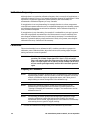
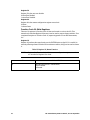
Product Warranty
RKI Instruments, Inc. warrants gas alarm equipment sold by us to be free from defects in
materials, workmanship, and performance for a period of one year from date of shipment
from RKI Instruments, Inc. Any parts found defective within that period will be repaired
or replaced, at our option, free of charge. This warranty does not apply to those items
which by their nature are subject to deterioration or consumption in normal service, and
which must be cleaned, repaired, or replaced on a routine basis. Examples of such items
are:
Warranty is voided by abuse including mechanical damage, alteration, rough handling, or
repair procedures not in accordance with the operator’s manual. This warranty indicates
the full extent of our liability, and we are not responsible for removal or replacement costs,
local repair costs, transportation costs, or contingent expenses incurred without our prior
approval.
THIS WARRANTY IS EXPRESSLY IN LIEU OF ANY AND ALL OTHER
WARRANTIES AND REPRESENTATIONS, EXPRESSED OR IMPLIED,
AND ALL OTHER OBLIGATIONS OR LIABILITIES ON THE PART OF
RKI INSTRUMENTS, INC. INCLUDING BUT NOT LIMITED TO, THE
WARRANTY OF MERCHANTABILITY OR FITNESS FOR A
PARTICULAR PURPOSE. IN NO EVENT SHALL RKI INSTRUMENTS,
INC. BE LIABLE FOR INDIRECT, INCIDENTAL, OR CONSEQUENTIAL
LOSS OR DAMAGE OF ANY KIND CONNECTED WITH THE USE OF
ITS PRODUCTS OR FAILURE OF ITS PRODUCTS TO FUNCTION OR
OPERATE PROPERLY.
This warranty covers instruments and parts sold to users by authorized distributors,
dealers, and representatives as appointed by RKI Instruments, Inc.
We do not assume indemnification for any accident or damage caused by the operation of
this gas monitor, and our warranty is limited to the replacement of parts or our complete
goods.
a) Absorbent cartridges d) Batteries
b) Pump diaphragms and valves e) Filter elements
c) Fuses

M2 Transmitter Operator’s Manual, 12 V DC Operation
Table of Contents
Chapter 1: Introduction . . . . . . . . . . . . . . . . . . . . . . . . . . . . . . . . . . . . . . . . . . . . . . . . . . . . . . . 1
Overview . . . . . . . . . . . . . . . . . . . . . . . . . . . . . . . . . . . . . . . . . . . . . . . . . . . . . . . . . . . . . 1
About the M2 Transmitter . . . . . . . . . . . . . . . . . . . . . . . . . . . . . . . . . . . . . . . . . . . . . . . 1
About this Manual. . . . . . . . . . . . . . . . . . . . . . . . . . . . . . . . . . . . . . . . . . . . . . . . . . . . . . 1
Specifications . . . . . . . . . . . . . . . . . . . . . . . . . . . . . . . . . . . . . . . . . . . . . . . . . . . . . . . . . . 2
Chapter 2: Description . . . . . . . . . . . . . . . . . . . . . . . . . . . . . . . . . . . . . . . . . . . . . . . . . . . . . . . 3
Overview . . . . . . . . . . . . . . . . . . . . . . . . . . . . . . . . . . . . . . . . . . . . . . . . . . . . . . . . . . . . . 3
External Description . . . . . . . . . . . . . . . . . . . . . . . . . . . . . . . . . . . . . . . . . . . . . . . . . . . . 3
Internal Description . . . . . . . . . . . . . . . . . . . . . . . . . . . . . . . . . . . . . . . . . . . . . . . . . . . . 4
Chapter 3: Installation & Startup . . . . . . . . . . . . . . . . . . . . . . . . . . . . . . . . . . . . . . . . . . . . . . 8
Overview . . . . . . . . . . . . . . . . . . . . . . . . . . . . . . . . . . . . . . . . . . . . . . . . . . . . . . . . . . . . . 8
Mounting the M2 Transmitter . . . . . . . . . . . . . . . . . . . . . . . . . . . . . . . . . . . . . . . . . . . . 8
Wiring the M2 Transmitter . . . . . . . . . . . . . . . . . . . . . . . . . . . . . . . . . . . . . . . . . . . . . . 9
Start Up . . . . . . . . . . . . . . . . . . . . . . . . . . . . . . . . . . . . . . . . . . . . . . . . . . . . . . . . . . . . . . 11
Chapter 4: Operation . . . . . . . . . . . . . . . . . . . . . . . . . . . . . . . . . . . . . . . . . . . . . . . . . . . . . . . . 13
Overview . . . . . . . . . . . . . . . . . . . . . . . . . . . . . . . . . . . . . . . . . . . . . . . . . . . . . . . . . . . . 13
Normal Operation . . . . . . . . . . . . . . . . . . . . . . . . . . . . . . . . . . . . . . . . . . . . . . . . . . . . . 13
Information Screen. . . . . . . . . . . . . . . . . . . . . . . . . . . . . . . . . . . . . . . . . . . . . . . . . . . . . 13
4 - 20 mA Signal Output Operation . . . . . . . . . . . . . . . . . . . . . . . . . . . . . . . . . . . . . . 13
Alarm Indications . . . . . . . . . . . . . . . . . . . . . . . . . . . . . . . . . . . . . . . . . . . . . . . . . . . . . 14
Chapter 5: Configuration Mode . . . . . . . . . . . . . . . . . . . . . . . . . . . . . . . . . . . . . . . . . . . . . . 17
Overview . . . . . . . . . . . . . . . . . . . . . . . . . . . . . . . . . . . . . . . . . . . . . . . . . . . . . . . . . . . . 17
Viewing & Changing M2 Parameters . . . . . . . . . . . . . . . . . . . . . . . . . . . . . . . . . . . . 17
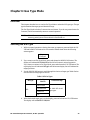
Chapter 6: Gas Type Mode . . . . . . . . . . . . . . . . . . . . . . . . . . . . . . . . . . . . . . . . . . . . . . . . . . . 20
Overview . . . . . . . . . . . . . . . . . . . . . . . . . . . . . . . . . . . . . . . . . . . . . . . . . . . . . . . . . . . . 20
Selecting the Gas Type . . . . . . . . . . . . . . . . . . . . . . . . . . . . . . . . . . . . . . . . . . . . . . . . . 20

M2 Transmitter Operator’s Manual, 12 VDC Operation
Chapter 7: Maintenance . . . . . . . . . . . . . . . . . . . . . . . . . . . . . . . . . . . . . . . . . . . . . . . . . . . . . 22
Overview. . . . . . . . . . . . . . . . . . . . . . . . . . . . . . . . . . . . . . . . . . . . . . . . . . . . . . . . . . . . . 22
Preventive Maintenance . . . . . . . . . . . . . . . . . . . . . . . . . . . . . . . . . . . . . . . . . . . . . . . . 22
Troubleshooting . . . . . . . . . . . . . . . . . . . . . . . . . . . . . . . . . . . . . . . . . . . . . . . . . . . . . . . 23
Calibration Frequency. . . . . . . . . . . . . . . . . . . . . . . . . . . . . . . . . . . . . . . . . . . . . . . . . . 25
Calibration. . . . . . . . . . . . . . . . . . . . . . . . . . . . . . . . . . . . . . . . . . . . . . . . . . . . . . . . . . . . 25
Replacing Components of the M2 . . . . . . . . . . . . . . . . . . . . . . . . . . . . . . . . . . . . . . . 28
Chapter 8: RS-485 Modbus Output . . . . . . . . . . . . . . . . . . . . . . . . . . . . . . . . . . . . . . . . . . . . 29
Overview. . . . . . . . . . . . . . . . . . . . . . . . . . . . . . . . . . . . . . . . . . . . . . . . . . . . . . . . . . . . . 29
Wiring the M2 in a Modbus System . . . . . . . . . . . . . . . . . . . . . . . . . . . . . . . . . . . . . . 29
Using the M2 in a 4-wire Modbus System . . . . . . . . . . . . . . . . . . . . . . . . . . . . . . . . . 31
Modbus Mode . . . . . . . . . . . . . . . . . . . . . . . . . . . . . . . . . . . . . . . . . . . . . . . . . . . . . . . . 31
Supported Modbus Functions . . . . . . . . . . . . . . . . . . . . . . . . . . . . . . . . . . . . . . . . . . . 33
Parts List . . . . . . . . . . . . . . . . . . . . . . . . . . . . . . . . . . . . . . . . . . . . . . . . . . . . . . . . . . . . . . . . . . 38
Appendix A: Control Button Quick Reference Guide. . . . . . . . . . . . . . . . . . . . . . . . . . . . 39
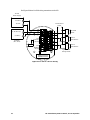
Appendix B: PLC and DCS Device Wiring . . . . . . . . . . . . . . . . . . . . . . . . . . . . . . . . . . . . . 40
Appendix C: Function Code 16 Registers. . . . . . . . . . . . . . . . . . . . . . . . . . . . . . . . . . . . . . . 42
(Appendix C available from RKI Instruments, Inc. Not in manual as normally provided
with M2 detector head.)

1 M2 Transmitter Operator’s Manual, 12 V DC Operation
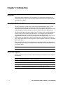
Chapter 1: Introduction
Overview
This chapter briefly describes the M2 Transmitter. This chapter also describes the M2
Transmitter Operator’s Manual (this document). Table 1 at the end of this chapter lists the
specifications for the M2.
About the M2 Transmitter
The M2 Transmitter is a fixed mount, continuous-monitoring detector head. All user
adjustable parameters may be accessed using push button switches. In addition,
calibration may be performed non-intrusively by use of a magnetic wand accessory which
activates magnetic switches through a window at the front face of the detector head.
The M2 displays the current gas reading on an LCD display which is visible through the
window in the cover (front face) and provides a 4 - 20 mA signal which indicates the
target gas reading for use by a gas monitoring controller, recording device, or
programmable controller. The M2 also provides an RS-485 Modbus output. Three sets of
relay contacts, two controlled by the gas alarms and one by the fail alarm, rated at 115
VAC 5 amps are available for controlling devices such as lights or horns or for controlling
higher rated relays.
Four operating modes allow you to display and change setup and calibration settings and
change the gas type. They are Calibration Mode, Configuration Mode, Gas Type Mode,
and Modbus Mode.
NOTE: Only the LEL version of the M2 is available for 12 VDC operation.
About this Manual
The M2 Transmitter Operator’s Manual uses the following conventions for notes, cautions,
and warnings.
NOTE: Describes additional or critical information.
CAUTION: Describes potential damage to equipment.
WARNING: Describes potential danger that can result in injury or death.

M2 Transmitter Operator’s Manual, 12 VDC Operation 2
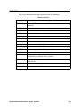
Specifications
Table 1 lists specifications for the M2.
WARNING: When using the M2, you must follow the instructions and warnings in
this manual to assure proper and safe operation of the M2 and to
minimize the risk of personal injury. Be sure to maintain and periodically
calibrate the M2 as described in this manual.
WARNING: M2 detector heads with firmware version 5.0 or later have a different
Modbus register assignment than M2s with previous versions of
firmware. If you are adding M2s with firmware version 5.0 or later to an
existing Modbus network installation, confirm what firmware version is
installed in the M2s already in the network and if necessary, take all steps
required to address the differences in Modbus register assignments. See
“Supported Modbus Functions” on page 33 for information on the current
Modbus register assignments. The firmware version is shown on the
Information Screen described on page 13.
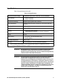
Table 1: M2 Specifications
Target Gas/Detection Range Combustible (LEL) Gas: 0 - 100% LEL, 1% LEL increments
Alarm Settings
*
• Alarm 1: 10 %LEL
• Alarm 2: 50 %LEL
Construction (housing) Explosion-proof Junction Box, NEMA 4
Area Classification Explosion-proof for Class I, Groups B, C, and D (LEL and toxic
versions)
Sampling Method Diffusion
Input Power 10.8 - 14.5 VDC
Controls • Three push button switches
• Three magnetic switches for non-intrusive calibration
Weight 4.5 lbs.
Signal Output • 4 to 20 mA, 350 ohms impedance max
• RS-485 Modbus
Operating Temperature -20°C to 50°C
Accuracy ± 5% of reading or ± 2% LEL (whichever is greater)
*
These are the RKI factory settings. You can change the alarm settings in Configuration Mode. See
“Viewing & Changing M2 Parameters” on page 17.

3 M2 Transmitter Operator’s Manual, 12 V DC Operation
Chapter 2: Description
Overview
This chapter describes external and internal components of the M2 Transmitter.
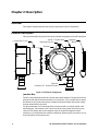
External Description
This section describes the junction box and all external components of the M2 transmitter.
Figure 1: M2 External Components
Junction Box
The M2’s cast aluminum junction box is dust and weather resistant. The junction box also
protects the M2 and all connections made to it. Use the two 3/4 in. conduit hubs to mount
the detector to the junction box (factory installed in the bottom hub) and connect wiring
from an external device (top hub).
Use the junction box’s two mounting holes to mount the M2 to a vertical surface at the
monitoring site. The window in the cover on the front of the junction box allows you to
view the LCD display and use the magnetic wand to actuate the magnetic control
switches so you can perform non-intrusive calibration. Removing the cover allows you to
access the interior of the junction box.
3/4NPT Conduit Hub Magnetic
Wand
Junction Box Cover
Detector
(Catalytic LEL DetectorShown)
Window
Mounting Slot (2x)

M2 Transmitter Operator’s Manual, 12 VDC Operation 4
Magnetic Wand
The magnetic wand is a short plastic rod with a magnet in one end. It is used to actuate
the magnetic control switches on the control PCB while the junction box cover is still
installed so that non-intrusive calibration can be performed.
LEL Detector
The LEL detector senses the target gas and is mounted in a 3/4” conduit hub on the right
bottom side of the M2. The LEL detector has a 1/2” NPT thread and requires a 3/4”NPT x
1/2”NPT reducer to mount it in the detector hub.
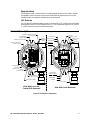
Internal Description
Figure 2: M2 Internal Components
TX LED
RXLED
Alarm 2 LED
Alarm 1 LED
Fail LED
Magnetic
Switches
Terminal PCB
Control PCB
UP/YES
ALARM 1
ENTER
DOWN/NO
Push Button
Control
Switches
C NC NO
RS 485
ALARM 2
LEL
C N C NO
R W G B
R W G B
A B C
RS 485
A B C
FAIL
C NC NO
PWR/SIG
LEL
- S +
PWR/SIG
- S +
Detector Terminal Strip
DetectorCurrent Pot
(Factory Adjust)
Power/Signal
Terminal Strip
Programming
Connector
(Factory Use)
Modbus
Terminal Strip
Display Ribbon
Cable Connector
UP/YES
DOWN/NO
ENTER
LCD Display
RKI INSTRUMENTS
M2 TRANSMITTER
Termination Jumper
View With Cover and
ControlPCBRemoved
3/4" NPT ConduitOpening
forWire Entry
View With Cover Removed
Relay
Terminal
Strips
Junction Box

5 M2 Transmitter Operator’s Manual, 12 V DC Operation
Terminal PCB
The terminal PCB is encapsulated in epoxy for protection against moisture and physical
damage. It is mounted into the rear of the junction box with three standoffs and rests on a
thin layer of foam. A banana jack is screwed into each of the standoffs and used for
mounting the control PCB. The terminal PCB converts the electrical output from the
detector to a signal which can be displayed by the LCD display, a 4 - 20 mA signal (that is
proportional to the detection range) and an RS-485 Modbus output signal. The 4 - 20 mA
signal may be used by a recording device, gas monitor controller, or programmable
controller. The Modbus output may be used to connect the M2 to a Modbus network. The
terminal PCB also controls three relays, one fail and two gas alarm relays.
Two columns of plug-in style terminal strips are used to make all wiring connections to
the M2. The column on the left consists of the power/signal, detector, and Modbus
terminal strips. The column on the right consists of the relay terminal strips. A 20 position
connector at the bottom of the terminal PCB is used to connect the terminal PCB to the
control PCB with a ribbon cable. A 5 position connector on the left side of the terminal
PCB is used by factory or field service personnel to program the M2. A factory adjust pot
just above the programming connector is used to set the LEL detector current.
Power/Signal Terminal Strip
The power/signal terminal strip is a three position plug-in style terminal strip located at
the top of the left terminal column. It is used to connect 12 VDC power to the M2 and to
connect the 4 - 20 mA output signal to a device.
The signal output, the S terminal, does not have to be connected for the M2 to function.
The S terminal is used if you want to connect the 4 - 20 mA output signal to another device
such as a gas monitoring controller, chart recorder, or programmable controller (PLC).
Detector Terminal Strip
The detector terminal strip is a four position plug-in style terminal strip and is the middle
terminal strip in the left terminal column. It is used to connect the LEL detector to the M2.
NOTE: The LEL detector is factory-wired to the M2. See “Wiring the M2 Transmitter”
on page 9 for all wiring procedures related to M2.
Modbus Terminal Strip
The Modbus terminal strip is a three position plug-in style terminal strip and is the
bottom terminal strip in the left terminal column. It allows connection of the M2 into a
Modbus network.
Relay Terminal Strips
The right column of terminal strips consists of, from top to bottom, the fail, alarm 1, and
alarm 2 relay terminal strips. They are three-position plug-in style terminal strips. The
relay terminal strips are used to connect devices such as lights and horns that are
controlled by the relay contacts. The relay contacts are rated at 115 VAC, 5 amps. The relay
contacts may also be used to control higher rated relays.
Termination Jumper
A two pin header with a termination jumper installed is located below the Modbus
terminal strip. The jumper has no function unless the M2 is wired into a Modbus
installation. See “Chapter 8: RS-485 Modbus Output” on page 29 for a description of using
the M2 in a Modbus system.

M2 Transmitter Operator’s Manual, 12 VDC Operation 6
Control PCB
The LCD display and control switches are located on the control PCB. It is installed on top
of the terminal PCB by lining up its three spacing standoffs with the banana jacks in the
terminal PCB mounting standoffs and pushing it onto the banana jacks. The jacks retain
the control PCB.
LCD Display
The LCD display is located at the top of the control PCB. It indicates the current gas
reading and displays messages and parameters in the M2’s programs.
Control Buttons
The M2 includes three push button switches that allow you to enter the M2’s operating
modes, navigate through the modes, update settings, and save changes to the settings.
The push button switches are located along the bottom edge of the control PCB (see
Figure 2). The UP/YES button is on the left, the DOWN/NO button is in the middle, and
the ENTER button is on the right.
Just above each push button switch is a magnetic switch with the same function as the
push button switch below it. The magnetic switches are for use in non-intrusive
calibration. They are actuated by bringing the magnetic wand close enough to them to
actuate them. Although the magnetic switches have the same functions as the push button
switches, it is not practical to use them for operations other than calibration because it is
not possible to actuate two magnetic switches at once with only one magnetic wand. Since
displaying the Information Screen only requires the use of one switch, the wand may be
used to show the Information Screen.
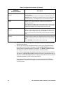
Table 2: M2 Control Button Functions
Switch Function
UP (YES) • Saves settings
• Changes the displayed setting
• Enters the Calibration Program
• Enters Gas Type Mode (press with DOWN/NO button)
• Enters Configuration Mode (press with ENTER button)
DOWN (NO) • Cancels setting changes
• Changes the displayed setting
• Enters Gas Type Mode (press with UP/YES button)
• Enters Modbus Mode (press with ENTER button)
• Displays the Information Screen
ENTER • Initiates operations
• Enters Configuration Mode (press with UP/YES button)
• Enters Modbus Mode (press with DOWN/NO button)
• Functions as an alarm reset switch

7 M2 Transmitter Operator’s Manual, 12 V DC Operation
Status LEDs
The M2 includes five status LEDs that are located above the display (see Figure 2).
• Fail LED
The fail LED turns on when the M2 is experiencing a fail condition. A fail condition
can be caused by a detector failure or low detector signal.
• Alarm 1 LED
The alarm 1 LED is on when the M2 is experiencing an alarm 1 condition.
• Alarm 2 LED
The alarm 2 LED is on when the M2 is experiencing an alarm 2 condition.
• RX & TX LED’s
These LED’s indicate data being received (RX) and transmitted (TX) when the M2’s
Modbus output is operating.

M2 Transmitter Operator’s Manual, 12 VDC Operation 8
Chapter 3: Installation & Startup
Overview
This chapter describes procedures to mount the M2 Transmitter in the monitoring
environment and wire it to input power and devices.
Mounting the M2 Transmitter
1. Select a mounting site that is representative of the monitoring environment. Consider
the following when you select the mounting site.
• Select a site where the M2 is not likely to be bumped or disturbed. Make sure
there is sufficient room to perform start-up, maintenance, and calibration
procedures.
• Select a site where the target gas is likely to be found first. For lighter gases,
mount the detector near the ceiling; for heavier gases, mount the detector near the
floor.
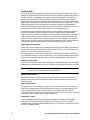
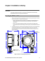
2. At the monitoring site, use #10 screws through the junction box’s two mounting holes
to secure the junction box to a vertical surface. Figure 3 shows the outline and
mounting dimensions of the M2. Mount the M2 with the detector facing down as
shown in Figure 3.
Figure 3: Outline & Mounting Dimensions, LEL
2.3 max
7.7 max
1.02
5.86
4.59
3/4 NPT
Conduit Hub
.47 (2X)
.30 (2X)
2.41
5.00
5.23
1 1/2-20 For
Calibration Cup

9 M2 Transmitter Operator’s Manual, 12 V DC Operation
Wiring the M2 Transmitter
WARNING: Always verify that the power source is OFF before making any wiring
connections.
1. Remove the junction box cover.
2. Grasp the control PCB by its edges.
3. Gently pull until the control PCB is pulled away from the banana jacks. Take care not
to pull too hard and damage the cable which connects the control and terminal PCB’s.
4. Let the control PCB hang by the cable. The terminal strips are now visible on the
terminal PCB. The control PCB may be left hanging while wiring is done. If desired,
the control PCB may be disconnected from the cable and set aside while wiring.
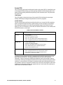
5. The detector leads are factory wired. Verify that the detector leads are wired to the
detector terminal strip as shown below: Red wire to terminal labeled LEL R, white
wire to terminal labeled LEL W, green wire to terminal labeled LEL G, black wire to
terminal labeled LEL B.
Figure 4: LEL Detector Wiring
6. To gain access to a plug-in terminal strip for wiring, pull it out of its socket by
grasping the wall between two terminal positions with needle nose pliers and pulling.
Be careful not to exert too much force on the wall to avoid damage to the terminal
strip. The detector terminal strip and the alarm 1 relay terminal strip may be removed
by grasping them with you fingers if the adjacent terminal strips have been removed.
7. Guide multi conductor shielded cable or cables or wires in conduit through the top
conduit hub of the junction box. The number of cables or wires needed will depend on
whether the M2 is wired to a gas monitoring controller or just to power, whether any
relays are used, and whether the Modbus output is used.
NOTE: If the M2 is being wired to a PLC or DCS device, see “Appendix B: PLC and
DCS Device Wiring” on page 40, then continue with step 8.
Use the following recommendations to determine how to wire the M2:
• If Modbus connections will not be used and only the PWR/SIG connections will
C NC NO C NC NO C NC NO
ALARM 2 ALARM 1 FAIL
A B C
RS 485
PWR/SIGLEL
S
R W G B
Black
Green
White
Red
A B C
RS 485
PWR/SIG
LEL
S
R W G B

M2 Transmitter Operator’s Manual, 12 VDC Operation 10
be used, use a two or three conductor shielded cable or two or three wires in
conduit for connections to the power/signal terminal strip depending on whether
or not the signal (S) terminal is used.
• If the PWR/SIG connections and one or more relays are used, route the
connections to the M2 in conduit. Use shielded cable in the conduit for the PWR/
SIG connections and unshielded cable or individual wires for the relay
connections. Make sure any wire or cable used for relay wiring is appropriately
rated for the power that it will carry.
NOTE: If shielded cable is used for the PWR/SIG connections, leave the cable shield’s
drain wire insulated and disconnected at the M2. You will connect the opposite
end of the cable’s drain wire at the controller or device.
• If the M2 will be wired into a Modbus network, see “Chapter 8: RS-485 Modbus
Output” on page 29.
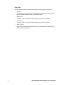
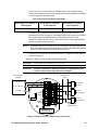
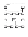
See Figure 5 below for field wiring connections to the M2.
CAUTION: Do not connect 24 VDC power to a 12 VDC M2.
WARNING: If the M2 is installed in a hazardous location, use appropriately rated
conduit, conduit fittings, and construction technique.
Figure 5: Wiring the M2 to a Controller and Alarm Devices
Table 3: Wire Size for PWR/SIG Connections
Max Distance to Controller w/
18 Gauge Wire
Max Distance to Controller
w/16 Gauge Wire
Max Distance to Controller
w/14 Gauge Wire
2,500 ft. 5,000 ft. 8,000 ft.
Alarm Device
Power
Fail Alarm
Device
Alarm 1
Alarm Device
Alarm 2
Alarm Device
Typical Alarm
Wiring Shown
FAIL
C NC NO
+
PWR/SIG
S
RKI Controller
Terminals
4 - 20 mAIn (S)
(12 VDC) -
ALARM 2
RS 485
A B C
See
Modbus
Wiring
(12 VDC) +
ALARM 1
C NC NO
TOXIC OXY
C NC NO
See
Detector
Wiring
+

11 M2 Transmitter Operator’s Manual, 12 V DC Operation
8. Re-install the control PCB (and ribbon cable if necessary). Be sure the ribbon cable is
routed down below the control PCB so it will not be damaged by the cover when it is
screwed back on.
9. Secure the junction box cover to the junction box.
10. Make controller, device, and relay connections as appropriate. If shielded cable is
used for the PWR/SIG connections, connect the cable shield’s drain wire to an
available chassis ground at the gas monitoring controller, recording device, or
programmable controller.
Start Up
Introducing Incoming Power
1. Complete the installation procedures described earlier in this manual.
2. Verify that all wiring connections are correct and secure.
3. Turn on the incoming power.
4. If necessary, turn on the controller or other monitoring device that is connected to the
M2.
5. The LCD display will indicate the firmware version when the M2 is first powered up
and will then count down a one minute warm-up period before normal operation
begins. During normal operation, the display will indicate the target gas and current
gas reading. Verify that the display is indicating the target gas and current gas reading
after the warm-up period is complete and normal operation begins.
CAUTION: Allow the M2’s detector to warm up for 15 minutes before you continue with the
next section, “Adjusting the Fresh Air Reading.”
Adjusting the Fresh Air Reading
When the M2 is shipped from RKI Instruments, Inc. it is factory calibrated. If a full
calibration is desired at startup, see “Calibration” on page 25.
Verify that the M2 is in a fresh air environment (environment known to be free of the
target gas and combustible or toxic gas vapors and of normal oxygen content, 20.9%).
CAUTION: If you suspect the presence of combustible gas, toxic gas, or that the oxygen content
is not normal in the monitoring environment, use the calibration kit and the zero
air calibration cylinder to introduce “fresh air” to the detector and verify an
accurate fresh air setting. See “Calibration” on page 25 for instructions on how to
use a zero air cylinder when performing a fresh air adjustment.
Non-Intrusive Fresh Air Signal Adjustment
If the M2 is installed in a classified area and non-intrusive zero adjustment is required,
follow the instructions below, but do not remove the junction box cover. Use the magnetic
wand accessory to actuate the magnetic switches instead of pushing the control switch
buttons. To actuate a magnetic switch and perform the same operation as pressing a
METHANE
0 %LEL

M2 Transmitter Operator’s Manual, 12 VDC Operation 12
control switch button, touch the magnet in the end of the magnetic wand to the M2’s glass
cover directly above the magnetic switch you wish to actuate. Touching the glass and
removing the wand is the same as pressing and releasing a button. Touching the glass and
keeping the wand in place is the same as pressing and holding a button.
WARNING: The M2 is not an active gas monitoring device during the calibration
procedure. The 4-20 mA output signal will “freeze” at 3.5 mA and all
relays will remain in their non-alarm state while the M2 is in Calibration
Mode. The output signal will not indicate current readings and the relays
will not resume operating normally until the M2 is in normal operation
again.
NOTE: While in the calibration program, if there is no switch activity for the
calibration time-out period the unit will return to normal operation. The factory
set time-out is 15 minutes. If you want a different time-out period, see
“Viewing & Changing M2 Parameters” on page 17 for instructions to change
the calibration time-out.
Adjusting the Fresh Air Reading
1. While in normal operation, press and hold the UP/YES button for 5 seconds to enter
Calibration Mode. Release the button when the following screen appears.
2. Press and release the UP/YES button to continue. The display will indicate the target
gas and CAL Mode for a few seconds before showing FreshAir Adjust?.
3. Press and release the UP/YES button. ENTER will alternate with FreshAir on the top
display line and the current gas reading will be on the bottom display line.
4. Press and release the ENTER button. The M2 will perform a zero operation and the
display will indicate SPAN w/Cal Gas?.
5. Press and release the DOWN/NO button. The display will indicate Leaving CAL
Mode and the M2 will return to normal operation.
Calib?
YES/NO

13 M2 Transmitter Operator’s Manual, 12 V DC Operation
Chapter 4: Operation
Overview
This chapter describes the M2 in normal operation. This chapter also describes the M2 in
alarm 1, alarm 2, and fail conditions and suggests response to these conditions.
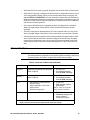
Normal Operation
Normal operation is defined as follows:
• The start-up procedure is complete.
• The M2 is not indicating an alarm 1, alarm 2, or fail condition.
• The M2 is not in Calibration, Configuration, or Gas Type modes.
During normal operation, the M2 simultaneously displays the current gas reading, unit of
measure, and target gas. The example below illustrates a typical LEL M2.
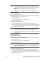
Information Screen
The Information Screen displays the M2’s operating voltage and firmware and hardware
information. To display the Information Screen, do the following:
1. Press and hold the DOWN/NO button for 3 seconds. The Information Screen will
appear.
2. Continue holding the DOWN/NO button to keep the Information Screen on the
display. The top line indicates the operating voltage that is connected to the M2. The
second line indicates the firmware that is running, version 5.0 in this example, and the
M2’s hardware version, version 1B in this example. This information may be useful if
you need to contact the factory with questions about the M2.
3. Release the DOWN/NO button when you are done viewing the Information Screen.
The display will return to the normal operation screen within a couple of seconds.
4 - 20 mA Signal Output Operation
The output at the S terminal of the power/signal terminal strip is a 4 - 20 mA signal that is
proportional to the detection range of the detector head. During normal operation, this
signal tracks the gas concentration on the LCD.
There are several circumstances where the signal output will not track the display reading
but will behave as follows:
METHANE
0 %LEL
12.1V
v5.0L 1B

M2 Transmitter Operator’s Manual, 12 VDC Operation 14
• When the M2 is in its warm-up period, the signal output will be fixed at 3.5 mA (zero).
• When the M2’s gas type is changed, the M2 will enter Configuration Mode for you to
verify the parameter settings. When you exit Configuration Mode, the display will
indicate NEEDS CALIBRATION and will continue to indicate this until Calibration
Mode is entered and a calibration is performed. In this situation, the signal output will
be fixed at 3.5 mA from the time Gas Type Mode is entered until the M2 is calibrated
and returns to normal operation.
• If you enter Calibration Mode, Configuration Mode, Gas Type Mode, or Modbus
Mode, the signal output will be fixed at 3.5 mA until the M2 returns to normal
operation.
• If the M2’s input power decreases below 10.5 volts so that the M2 is in a low power
alarm, the signal output is fixed below 2.4 mA until the low power alarm is cleared.
• If the M2 goes into a fail condition, after a 30 second delay, the signal output is fixed
below 2.4 mA until the fail alarm is cleared. During the 30 second delay, the signal
output follows the detector output. In the case of a downscale reading, the display
and the signal output continue to track the reading down to -99% of full scale (1.15
mA).
Alarm Indications
NOTE: The M2 includes alarm on and alarm off delay settings for alarm 1 and alarm 2.
The alarm indications described in this section operate according to the factory
set alarm settings. See Table 5 on page 18 for all the factory settings.
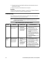
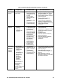
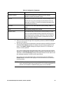
Table 4: Visual and Audible Alarm Indications
Condition Cause Visual Indication(s)
Alarm 1
1
Increasing gas reading at or above the
alarm 1 setpoint
• A1 LED is on
• Gas reading alternates
with ALARM-1 message
Alarm 2
1
Increasing gas reading at or above the
alarm 2 setpoint
• A2 LED is on
• Gas reading alternates
with ALARM-2 message
Fail • Disconnected or misconnected
detector wiring
• Display reading at -10% of full
scale or lower
• Defective components
• F LED is on
• FAIL message replaces
gas reading
NOTE: There is a 30 second
delay on the fail condition.
Low Power DC power source less than 10.5 volts. • F LED is on
• LowPower message and
actual voltage of
incoming DC power
*
1
If the M2 is in both an alarm 1 and an alarm 2 condition, both alarm LEDs are on and the
display alternates between the gas reading and the ALMS 1&2 message.

15 M2 Transmitter Operator’s Manual, 12 V DC Operation
NOTE: You can select normally energized (N. EN) or normally de-energized (N. DE-
EN) alarm 1 and alarm 2 relay settings in Configuration Mode. The following
sections describe the standard factory setting for these relays which is
N. DE-EN.
The fail relay is factory set as N. DE-EN and is not user-adjustable.
Alarm 1 Condition
Alarm 1 Condition Indications
When the gas reading reaches the alarm 1 setpoint, the M2 senses an alarm 1 condition.
The M2 alerts you to an alarm 1 condition as follows:
• The A1 LED turns on.
• The gas reading alternates with the ALARM-1 message.
• The alarm 1 relay energizes.
Responding to an Alarm 1 Condition
1. Follow your established procedure for a low level combustible gas condition.
2. After the gas reading falls below the alarm 1 setpoint, press the ENTER button to reset
the alarm 1 circuit. Resetting the alarm 1 circuit turns off the A1 LED, resets the LCD,
and de-energizes the alarm 1 relay.
NOTE: If the ENTER button is pressed while the M2 is in an alarm 1 condition, the A1
LED will flash but all other indications will remain unchanged.
You cannot de-energize the alarm 1 relay until the gas reading falls below the
alarm 1 setpoint.
Alarm 2 Condition
Alarm 2 Condition Indications
When the gas reading reaches the alarm 2 setpoint, the M2 senses an alarm 2 condition.
The M2 alerts you to an alarm 2 condition as follows:
• The A2 LED turns on.
• The gas reading alternates with the ALARM-2 message.
• The alarm 2 relay energizes.
NOTE: If the M2 is in both an alarm 1 and alarm 2 condition, both the A1 and A2 LEDs
will be on, the gas reading will alternate with the ALMS 1&2 message, and
both alarm relays will energize.
Responding to an Alarm 2 Condition
1. Follow your established procedure for a high level combustible gas condition.
2. After the gas reading falls below the alarm 2 setpoint, press the ENTER button to reset
the alarm circuit. Resetting the alarm circuit turns off the A2 light, resets the LCD, and
de-energizes the alarm 2 relay.
Page is loading ...
Page is loading ...
Page is loading ...
Page is loading ...
Page is loading ...
Page is loading ...
Page is loading ...
Page is loading ...
Page is loading ...
Page is loading ...
Page is loading ...
Page is loading ...
Page is loading ...
Page is loading ...
Page is loading ...
Page is loading ...
Page is loading ...
Page is loading ...
Page is loading ...
Page is loading ...
Page is loading ...
Page is loading ...
Page is loading ...
Page is loading ...
Page is loading ...
Page is loading ...
Page is loading ...
Page is loading ...
Page is loading ...
-
 1
1
-
 2
2
-
 3
3
-
 4
4
-
 5
5
-
 6
6
-
 7
7
-
 8
8
-
 9
9
-
 10
10
-
 11
11
-
 12
12
-
 13
13
-
 14
14
-
 15
15
-
 16
16
-
 17
17
-
 18
18
-
 19
19
-
 20
20
-
 21
21
-
 22
22
-
 23
23
-
 24
24
-
 25
25
-
 26
26
-
 27
27
-
 28
28
-
 29
29
-
 30
30
-
 31
31
-
 32
32
-
 33
33
-
 34
34
-
 35
35
-
 36
36
-
 37
37
-
 38
38
-
 39
39
-
 40
40
-
 41
41
-
 42
42
-
 43
43
-
 44
44
-
 45
45
-
 46
46
-
 47
47
-
 48
48
-
 49
49


RKI Instruments M2 for 12 VDC User manual
- Category
- Carbon monoxide (CO) detectors
- Type
- User manual
Ask a question and I''ll find the answer in the document
Finding information in a document is now easier with AI
Related papers
-
RKI Instruments M2 65-2619RK-HC-04 Owner's manual
-
-
-
-
-
-
-
-
RKI Instruments 65-2661RK-XX-04 Owner's manual
-
Other documents
-
NetSafety Millennium SIR100 IR Combustible Gas Detector Owner's manual
-
-
Bacharach MGS-400 User manual
-
Rae RAEGuard EC User manual
-
Comelit 30009004 User manual
-
-
-
Schneider Electric Network Management Card 2 and 3 Modbus System user guide
-
 PureAire 99185 Remote Digital Display Alarm Indicator User manual
-
 Ansee BWR-01A Operation Instructions

