Pottinger NOVADISC 222 Operating instructions
- Category
- Kitchen & houseware accessories
- Type
- Operating instructions
This manual is also suitable for

Operator‘s manual
Translation of the original Operating Manual
Nr. 99+3741.EN.80X.0
Disc mower
NOVADISC 222
(Type PSM 3741 : + . . 01001)
NOVADISC 262
(Type PSM 3742 : + . . 01001)
NOVADISC 302
(Type PSM 3743 : + . . 01001)
NOVADISC 352
(Type PSM 3744 : + . . 01001)

1900_GB-PAGE 2
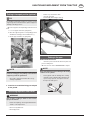
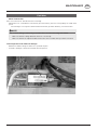
Product liability, information obligation
Product liability obliges manufacturers and dealers to issue operating instructions for the machine at the point of sale and to instruct
the customer on the operation, safety and maintenance regulations governing the machine.
Confirmation is required to prove that the machine and the operating instructions have been properly handed over. For this purpose
you have received a confirmation e-mail from Pöttinger. If you have not received this mail, please contact your local dealer. Your
dealer can fill in the handover declaration online.
For the purposes of product liability law, every farmer is an entrepreneur.
In the terms of product liability law, damage to property is any damage arising due to the machine, but not to the machine, and an
excess (500 euros) exists for this liability.
Corporate damage to property within the terms of the product liability law is excluded from this liability.
Be advised! The operating instructions must also be handed over with any subsequent machine sale or transfer and the transferee
must be instructed in the regulations stated.
Pöttinger - Trust creates Afnity - since 1871
"Quality pays for itself." Therefore we apply the highest quality standards to our products which are constantly monitored by our
in-house quality management and our management board. Because the safety, perfect function, highest quality and absolute
reliability of our machines in operation are the core competencies for which we stand.
There may be deviations between these instructions and the product as we are constantly developing our products. Therefore no
claims may be derived from the data, illustrations and descriptions. Please contact your Specialist Service Centre for any binding
information about specific features of your machine.
We would ask you to please understand that changes to the scope of supply with regard to form, equipment and technical
specifications are possible at any time.
Any form of reprint, translation or reproduction, including excerpts, requires the written approval of Pöttinger Landtechnik GmbH.
All rights according to copyright laws remain expressly reserved by Pöttinger Landtechnik GmbH.
© Pöttinger Landtechnik GmbH – 31st October 2012
Refer to PÖTPRO for additional information about your machine:
Are you looking for suitable accessories for your machine? No problem! All the information you require is here at your disposal.
Scan the QR code on the machine's type plate or look under www.poettinger.at/poetpro
And if we don't have what your looking for, then your Specialist Service Centre is there for you with help and advice.

DE-1901 Dokum D Attachments - 3 -
PÖTTINGER Landtechnik GmbH
Industriegelände 1
4710 Grieskirchen, Austria
Tel. 07248 / 600 -0
Telefax 07248 / 600-2511
Please place a cross where appropriate. X
According to the product liability please check the above mentioned items.
INSTRUCTIONS FOR PRODUCT HANDOVER
Confirmation is required to prove that the machine and the operating instructions have been properly handed over. For this purpose you have
received a confirmation e-mail from Pöttinger. If you have not received this mail, please contact your local dealer. Your dealer can fill in the hand-
over declaration online.
Machine checked according to delivery note. All attached parts removed. All safety equipment, drive shaft and operating
devices at hand.
Operation, commissioning and maintenance of the machine or device discussed and explained to the customer on the basis
of the operating instructions.
Check tyres for correct air pressure.
Check wheel nuts for tight t.
Correct PTO shaft speed indicated.
Adaptation to the tractor carried out: Three point adjustment
Cardan shaft correctly cut to length.
Test run carried out and no defects detected.
Function explanation during test run.
Swivel in transport and working position explained.
Information about optional equipment is given.
Indication of unconditional reading of the operating instructions.
EN

- 4 -
2400_GB-INHALT_385
Table of conTenTs EN
Safety hints
to observe
in supplement!
Table of contents
SYMBOLS USED
CE mark ..................................................................... 5
Safety hints: ............................................................... 5
Introduction ................................................................ 6
Meaning of the transfers ............................................ 7
Transfer position ........................................................ 8
TRACTOR REQUIREMENTS
Tractor ........................................................................ 9
Ballast weights ........................................................... 9
Lifting unit (three-point linkage) ................................. 9
Hydraulic control on the lifting gear ........................... 9
Necessary hydraulic connections ............................ 10
Power connections required .................................... 10
HITCHING IMPLEMENT TO TRACTOR
Safety advice ............................................................11
Hitching implement to tractor ....................................11
UNHITCHING IMPLEMENT FROM TRACTOR
General tips ............................................................. 13
Parking in the working position ................................ 13
Parking in transport position (optional) .....................14
Unhitching implement from tractor ............................14
Parking in the open ...................................................14
TRANSPORT POSITION
General safety information ....................................... 15
Transport position (T) ............................................... 15
Starting situation ...................................................... 15
Switching to transport position ................................. 15
Road Transport ........................................................ 16
Lighting for road travel ............................................. 16
WORKING POSITION
General safety information ........................................17
Initial situation for lowering the cutter bar .................17
Change to working position ......................................17
WORKING ON SLOPES
Working on slopes ................................................... 18
STARTING WORK
Safety advice ........................................................... 19
Starting work ............................................................ 19
Turning when mowing .............................................. 20
MOWING
Mowing .................................................................... 21
Reversing ................................................................. 21
General guidelines on working with the machine ... 22
Collision Avoidance ................................................. 22
Straw divider ........................................................... 22
FITTING OPTIONAL EQUIPMENT
Safety advice ........................................................... 23
1. Wear and high cut skids ....................................... 23
2. Swath former ....................................................... 24
3. Additional swath former ....................................... 25
4. Protective apron ................................................... 26
5. Conveying cones (optional) ................................. 26
GENERAL MAINTENANCE
Safety advice ........................................................... 27
General maintenance information ............................ 27
Cleaning of machine parts ....................................... 27
Parking in the open .................................................. 27
Winter storage.......................................................... 27
Articulated shafts ..................................................... 28
Hydraulic unit ........................................................... 28
MAINTENANCE
General safety information ....................................... 29
Oil level check, angular gear.................................... 29
Angular gear oil change ........................................... 29
Cutter bar oil level check .......................................... 30
Cutter bar oil change ............................................... 31
Setting the pre load of the folding aid ...................... 31
Installing cutter blades ............................................ 32
Factory setting of the relief springs .......................... 33
V-belt drive .............................................................. 34
Hydraulic plan .......................................................... 35
Wear control cutting blades bracket ......................... 36
MAINTENANCE
Holder for the rapid change of mowing blades ....... 37
Mowing blades suspension checks ........................ 37
Changing the cutting blades (from year of construction
2004) ........................................................................ 37
Storing of the lever ................................................... 38
TECHNICAL DATA
Technical data .......................................................... 39
The designated use of the mower unit ..................... 39
Optional equipment: ................................................. 39
Necessary connections............................................ 39
Type plate position ................................................... 40
Type plate position ................................................... 40
SUPPLEMENT
SAFETY ADVICE
Lubrication chart ...................................................... 47
NOVACAT 222 ......................................................... 48
NOVACAT 262 ......................................................... 48
NOVACAT 302 ......................................................... 48
NOVACAT 352 ......................................................... 48
Lubricants ................................................................ 49
SUPPLEMENT
Mounting options ..................................................... 52
TAPER BUSHES
Taper bushes installation instructions ...................... 53
Combination of tractor and mounted implement ...... 54

- 5 -
1801_EN-Sicherheit ANSI
EN
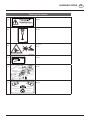
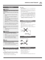
SymbolS uSed
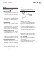
CE mark
The CE mark, which is affixed by the manufacturer, indicates outwardly that this machine conforms to the engineering
guideline regulations and the other relevant EU guidelines.
EU Declaration of Conformity (see Attachment)
By signing the EU Declaration of Conformity, the manufacturer declares that the machine that
is brought into service complies with all relevant fundamental safety and health requirements.
Safety hints:
These Operating Instructions contain the
following Figures:
DANGER
If you do not follow the instructions in a text section
with this marking, there is a risk of fatal or life-
threatening injury.
• All instructions in such text sections must be
followed!
WARNING
If you do not observe the instructions marked this
way, there is the risk of a severe injury.
• All instructions in such text sections must be
followed!
CAUTION
If you do not observe the instructions marked this
way, there is the risk of an injury.
• All instructions in such text sections must be
followed!
NOTE
If you do not observe the instructions marked this
way, there is the risk of material damage.
• All instructions in such text sections must be
followed!
TIP
The text sections marked in this way provide you with
special recommendations and advise regarding the
economical use of the implement.
ENVIRONMENT
The text sections marked in this way provide practices
and advice on environmental protection.
The features marked as (optional) are only available as
standard with specific implement versions or are only
offered for specific versions as optional equipment or are
only offered in certain countries.
Figures may deviate from your implement in detail and are
to be taken as illustrations of operating principle.
Designations such as right and left always apply as the
direction of travel unless the text or illustrations clearly
show otherwise.

- 6 -
EN
IntroductIon
1700_GB-Introduction
Introduction
Dear Customer
These Operating Instructions are intended to allow you
to familiarise yourself with the implement and provide
you with clear information on safe and correct handling,
care and maintenance. Thus please take the time to read
these Instructions.
These Operating Instructions comprise part of the imple-
ment. They are to be kept at a suitable location and acces-
sible to staff over the entire service life of the implement.
Instructions based on the national provisions regarding
protection against accidents, road traffic and environmental
protection are also to be applied additionally.
Any persons commissioned with the operation, maintenance
or transport of the implement must read and understand
these Instructions, in particular the safety information, prior
to starting work. Any warranty claims lapse on non-obser-
vance of these Instructions.
In case you have questions related to this operation manual
or further questions about this implement, please contact
your dealer.
Care and maintenance performed in good time and scru-
pulously according to the maintenance intervals specified
ensure operational and traffic safety as well as the reliability
of the implement.
Use only the original spare parts and accessories from
Pöttinger or accepted by Pöttinger. For those parts relia-
bility, safety and suitability for Pöttinger machines can be
assured. Warranty claims lapse if non-approved parts are
used. The use of original parts is also recommended after
the warranty period has expired to maintain the performance
of the implement in the long term.
Product liability legislation obliges the manufacturer and
the authorised dealer to issue Instructions when selling
implements and to instruct customers in the use with refer-
ence to the safety, operating and maintenance regulations.
Confirmation in the form of a declaration of transfer is
required to verify that the implement and Instructions have
been transferred correctly. The declaration of transfer was
attached to the implement on delivery.
Every self-employed person and farmer is an entrepreneur
within the meaning of the product liability legislation. In
accordance with the laws of product liability, entrepre-
neurial property damages are excluded from the liability.
All damage to property within the meaning of the product
liability legislation is regarded as damage caused by the
implement but not to the implement.
These Operating Instructions are integral part of the imple-
ment delivery scope. You should therefore hand them over to
the new owner if ownership of the implement is transferred.
Train and instruct the new owner in the regulations stated.
The Pöttinger Service-Team wishes you good luck.

- 7 -
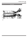
1900_GB-Warning signs_3741
EN
Warning signs
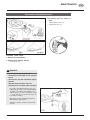
Meaning of the transfers
1
(1x)
Check belt tension:
494,355
2
(1x)
Open protection
495,727
3
(2x)
Never reach into the crushing danger area as long as parts can
move there.
495,171
4
(1x)
f
Datum / Date
Name
Benennung / Discription
AZB "Fettschmierung"
e
gez. / issued 18.03.1993
Huemer
d
c
A4
H
C
00
Zeichnungsnummer / DrawingNo.
494.646
Revision
0
b
a
Blatt / von
Sheet / of
1 / 1
Status
SERIE
Datum/Date Nr. Name
Datenblatt / Datasheet
Plot: 21.01.2016 15:57
Änderungen / Modification
A
llgemeine Anforderungen und Zeichnungsangaben siehe WN 007.022-1
G
eneral requirements and drawing entities refer to WN 007.022-1
© Pöttinger Landtechnik GmbH
AZB „grease lubrication“
Ausführung laut
Design according to WN 007.025
Farben:
Schrift und Grafik: verkehrsschwarz RAL 9017
Hintergrund: verkehrsgelb RAL 1023
46
mm
27
mm
Zuschnittlinie
05.09.16
5594/0006 donamar
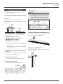
Position of a grease nipple
494,646
5
(1x)
Lifting gear height H1=0
495,757
6
(1x)
434.960 434.961
434.969.999 434.970.999
495.855/19
Blade equipment
495,855

- 8 -
1900_GB-Warning signs_3741
EN
Warning signs
123-18-16
Transfer position

- 9 -
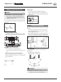
1400-D_TracTor requiremenTs_3834
EN
TracTor requiremenTS
Tractor
To operate this machine the following tractor requirements are necessary:
- Tractor power: NOVADISC 222 - from 103KW / 140PS
NOVADISC 262 - from 103KW / 140PS
NOVADISC 302 - from 103KW / 140PS
NOVADISC 352 - from 103KW / 140PS
- Hitching: Lower link Cat. III / width 3
- Connections: see table “Necessary hydraulic and power connections”
Ballast weights
Ballast weights
The front of the tractor must have sufficient ballast weights
to guarantee braking and steering capabilities.
DANGER
Life hazard - Steering or brake system failure due to
inadequate weight distribution between the tractor
axles.
• Make sure that when the implement is
hitched, at least 20% of the tractor weight is
placed on the front axle.
Lifting unit (three-point linkage)
- The tractor’s lifting unit (three-point linkage) must be designed for the applicable load. (See technical data)
- The lifting struts are to be set at the same length (4)
using the appropriate adjusting device
(See the tractor manufacturer’s operating manual)
- If the lifting struts on the lower links can be fixed in
different positions, then the rear position must be
selected. This relieves the pressure on the tractor’s
hydraulic system.
- The limiting chain or lower link stabilisers (5) are to
be set so that the attached machine CANNOT move
sideways. (Safety measure for transportation)
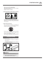
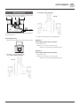
Hydraulic control on the lifting gear
The lifting hydraulics must be switched to position control:
20%
Kg
371-08-16
371-08-16

- 10 -
1400-D_TracTor requiremenTs_3834
TracTor requiremenTs EN
Necessary hydraulic connections
Design Consumer
Dual action hydraulic
connection with floating
position
Single-acting hydraulic
connection
Standard Lifting cylinder, folding cylinder
or hydraulic relief
X
Variant Lifting cylinder, folding cylinder
or hydraulic relief
X
Option hydraulic side protection flap X
Operating pressure
NOTE
Material hazard - Friction wear on the piston of the control or hydraulic
block due to incompatible hydraulic oils.
• Check the compatibility of the hydraulic oils before connecting
the implement to the hydraulic system of your tractor.
• Do not mix mineral oils with bio oils!
Minimum operating
pressure
170 bar
Maximum operating
pressure 200 bar
Power connections required
Design Consumer Pin Volt Power connection
Standard Lighting 7-pin 12 V DC According to DIN-
ISO 1724
Standard Control unit 3-pin 12 V DC According to DIN
9680

- 11 -
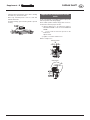
2000-EN Application_3741
EN
HiTcHing implemenT To TracTor
Safety advice
DANGER
Life-threatening danger through operating a machine
that is unroadworthy or damaged
• Check the vehicle for roadworthiness prior
to every operation (lights, brakes, protective
panels …)!
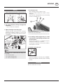
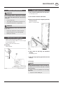
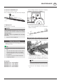
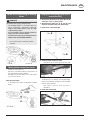
Hitching implement to tractor
1. Lock the implement at the 3-point headstock.
- Attach the mower so that the distance between the
inner mower disc and the tractor tyres is 0 - 10 cm. See
chapter "Mounting variants”
0 - 10 cm
TD 39/96/3
- Adjust the lower link bolts (1) on the bearing frame,
according to the three-point category, and the track
width using the fixing screw. The mower must not touch
the rear tractor tyres.
NOTE
Risk of damage to property due to an
implement coming loose from the tractor.
If the screw is only fixed in the bracket and does not
reach the hole in the bolt, the lateral movement of the
bolt is still possible and the mower can come loose
from the coupling.
• Check the tight connection between screw
(1) and coupling pin.
3 drilled holes
Locating screw
- See information in the Attachment to these Operating
Instructions for dual wheels or specially wide tyres
2. Connect hydraulic plug connections
For fold cylinders / relief to double-action hydraulic
connection:
Connect both black plug connections (relief) to a double-
action hydraulic connection on the tractor.
For fold cylinders / relief to single-action hydraulic
connection (optional):
Connect black plug connection (relief) to a single-action
hydraulic connection.
For hydraulic side protection flap (optional):
Connect both grey plug connections to a double-action
control device.
3. Position flap release rope (S) in the tractor
cabin.

- 12 -
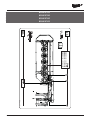
2000-EN Application_3741
AttAching implement to trActor EN
4. Adjust upper linkage spindle
- The mower is positioned horizontal or slightly
forwards by turning the upper linkage spindle (16).
5. Secure lower linkage (4) against lateral
movement.
6. Place support feet in parking position and
secure them
TIP
An horizontally parked mower requires one support leg
and a vertically parked mower requires two support legs.
1. Loosen support stand lock (spring bolts)
2. Put support stand in park position
3. Check support stand lock (spring bolts)
NOTE
Property damage if the unlocked support stand drops
down while travelling. Secure parking on the damaged
support stand can no longer be guaranteed.
• Check support stand lock after every posi-
tion change.
7. Attach the cardan shaft
- Before initial operation, check the cardan shaft length
and adapt if necessary. See chapter "CARDAN SHAFT"
in Supplement B also.
8. Check the pretensioning pressure of the folding
aid.
(single-acting hydraulic connection for optional
equipment)
1
1. Check the preload pressure on the pressure gauge
(1) mounted on the mounting frame.
2. Correct preload pressure if necessary. (See chapter
Maintenance: “Setting the pre load of the folding aid”)
TIP
The pressure required to make the folding aid work
is around 70 bar and varies from tractor to tractor.

- 13 -
1900-GB DISMANTLE_3741
EN
unHiTcHing implemenT from TracTor
General tips
DANGER
Life-threatening danger through tipping.
• Make sure the machine is standing securely.
Check the locking mechanism of the support
feet.
• Park the implement only on flat, firm ground.
DANGER
Life-threatening danger exists if another person starts
up the tractor and drives away or actuates the control
lever of the hydraulic system while you are engaged
in maintenance.
• Before dismantling, switch off the engine,
remove the key and brake the tractor.
DANGER
Life-threatening danger should the tractor start
moving on its own.
• Before dismantling, switch off the engine,
remove the key and brake the tractor.
• Secure the machine with chocks if neces-
sary.
The machine can be parked in the working position or the
transport position.
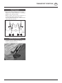
Parking in the working position
1. Swing flap up with rope (S)
- Flap position "B"
2. Swivel the cutter bar hydraulically down to the
ground.
- Actuate control valve (ST)
- Release rope (S) during swivel movement
ST-24-11-2003
TD 39/96/18
3. Move the support feet to the parking position
and secure them
1. Loosen support stand lock (spring bolts)
2. Move the support leg to the correct parking position.
Shutdown in working position: middle hole (2)
3. Check support stand lock (spring bolts)
1
2
NOTE
Property damage - if the locking device of the support
feet does not engage. Safe parking on the unlocked
support leg cannot be guaranteed.
• Check the support stand lock after every
change of position.
4. Lower the tractor with the lifting gear and park
on the ground.

- 14 -
1900-GB DISMANTLE_3741
Unhitching implement from tractor EN
Parking in transport position (optional)
TIP
For parking in transport position you need a second
support leg, which is included in the optional equipment
"Parking in working position".
1. Move the support feet to the parking position and secure
them
1. Loosen support stand lock (spring bolts)
2. Move the support leg to the correct parking position.
Shutdown in working position: middle hole (1)
3. Check support stand lock (spring bolts)
1
2
NOTE
Property damage - if the locking device of the support
feet does not engage. Safe parking on the unlocked
support leg cannot be guaranteed.
• Check the support stand lock after every
change of position.
2. Lower the tractor with the lifting gear and park
on the ground.
Unhitching implement from tractor
WARNING
Risk of injury resulting in death or other serious
injury if the unit tilts.
• Before uncoupling, check again whether the
stand is correctly locked.
- Disconnect hydraulic line.
- Detach upper link
- Remove rope from tractor cabin
- Uncouple lower link
- Pull off PTO shaft and lay it down (3)
3
Parking in the open
At the end of the season
- Clean the piston rod and all other bare parts and
preserve with grease.
- Observe the notes in the "MAINTENANCE" chapter.
NOTE
Risk of material damage due to damage to the sealing
elements of the cylinder.
• A rusty piston rod can damage the sealing
elements of the cylinder.
When parking in the
open for longer periods, clean piston rods and
then preserve with grease.
FETT
TD 49/93/2

- 15 -
1900_GB-TRANSPORT_3741
EN
TranSporT poSiTion
General safety information
DANGER
Danger to life - due to the mower tipping
• Change from the working to the transport
position only on level, solid ground.
DANGER
Life-threatening danger through rotating or ejected
components
• Switch off the cutter bar drive.
• Wait until the cutter bar has stopped moving
before swivelling it up.
• Never let the mower run when raised.
• Lower the machine completely or switch it
off when leaving the tractor cab.
DANGER
Danger to life - due to moving parts
• Make sure that the swivel range is clear and
that no-one is standing in the danger area.
Transport position (T)
Starting situation
1. Machine attached to the tractor
- see chapter "Attaching the implement to the tractor"
2. Machine in working or headland position
3. Support stand folded up and secured
Switching to transport position
NOTE
Risk of material damage when changing to
transport position due to braked cardan shafts.
• On tractors equipped with a cardan shaft
brake, this must be switched off before
switching to the transport position.
1. Swivel the transport safeguard up using the
rope (S)
- Transport safeguard position "B”
2. Move cutter bar to transport position
- Actuate control valve (ST)
- Release rope (S) when swivelling
- Engage transport safeguard (T1)
3. Locking the transport safeguard
- Set the control valve (ST) briefly to "lower" (S).
This ensures that the transport safeguard catch engages
firmly in the hook (T1) and fixes the cutter bar in the
transport position (T).

- 16 -
1900_GB-TRANSPORT_3741
TransporT posiTion EN
Road Transport
• Observethestatutoryregulationsforyourcountry.
Supplement C contains information on attaching a
lighting system, valid for Germany.
• Driving on public roads may only be carried out as
described in the Chapter "Transport position".
- Fasten the hydraulic lower link (4), so that the machine
cannot swivel out to the side.
Lighting for road travel
A lighting unit can be supplied on request (1).
See list of individual spare parts.
- Connect the lighting and raise the unit for transport.

- 17 -
0401-EN WorkiNg positioN_385
EN
Working poSiTion
General safety information
DANGER
Life-threatening danger through the mower tipping
over
• Change from the working to the transport
position only on level, solid ground.
DANGER
Life-threatening danger through rotating or ejected
components
• Switch off the cutter bar drive.
• Wait until the cutter bar has stopped moving
before swivelling it up.
• Never let the mower run when raised.
• Lower the machine completely or switch it
off when leaving the tractor cab.
DANGER
Life-threatening danger through moving parts
• Make sure that the swivel range is clear and
that no-one is standing in the danger area.
Initial situation for lowering the cutter
bar
1. Machine attached to the tractor
- see chapter "Attaching the implement
to the tractor"
2. Cutter bar in transport position
3. The swivel fields are in transport position,
raised and secured
Change to working position
1. Loosen the transport lock
- Before doing this, briefly set the hydraulic control
unit (ST) to "LIFT" to release the transport lock in
the hook.
- Use rope (S) to bring transport safety device into
position "B”
2. Lower cutter bar
For dual-action hydraulics:
- Set the hydraulic control unit (ST) to "DOWN" and
lower to the ground.
- Release rope (S) when swivelling
TIP
Lower the cutter bar to "pressure" if a dual-action
control unit is connected. The movement is
controlled and even and protects the machine.
Otherwise (when lowering to the float position)
the downward movements will be in jerks and
jolts. Increased stress will be placed on the joints.
For single-action hydraulics:
- Set the hydraulic control unit (ST) to "FLOAT POSITION"
and lower to the ground.
3. Close front protection cover (5a)
• Use only with closed protective cladding.

- 18 -
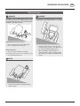
(358) 9500-gb driving on slopes
EN
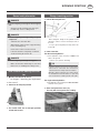
Working on SlopeS
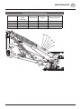
DANGER
Life hazard - due to tandem tipping. The tractor's
travelling characteristics are influenced by the weight
(G) of the mower unit. This can lead to dangerous
situations, especially on slopes.
TD15/95/3
G
Tipping hazard on slopes is present
• whenthemowingunitsareliftedhydraulically
• whenbendingwithliftedmowingunit
Counter-measures:
• Reducespeedwhenbendingaccordingly.
•Itisbettertotravelinreverseonaslopethantocarry
out a risky turning manoeuvre.
NOTE
Material hazard - due to unnoticed obstacles
TD15/95/2
• Raise the mower when driving backwards
and reversing!
Working on slopes
DANGER
Life hazard - due to tandem tipping. There is a danger
of tipping when swivelling the implement on headland.
TD15/95/4
• Swivel the cutter units successively to the
"Field transport" position or the "Work" posi-
tion using the individual lifting device.
• When swivelling in "field transport" or
"working position": Always swing the uphill
side mower first and then the downhill side
mower!

- 19 -
1900-GB OPRATINGNAHME_3741
EN
STarTing Work
Starting work
1. Check
- Check condition of blades and blade holder.
- Check mowing discs for damage (see chapter
"Maintenance and Service").
2. Only switch the machine on in working position
and do not exceed the specified p.t.o. speed
(max. 540 rpm)!
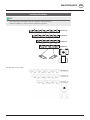
A transfer, located near the gearing, advises which p.t.o.
speed your mower unit is equipped for.
540 Upm 1000 Upm
• Always,andonly,switchthep.t.o.driveonwhenallsafety
devices (covers, protective aprons, casings, etc.) are
in proper condition and are attached to the machine in
their safety positions.
3. Pay attention to correct
p.t.o. direction of rotation!
TD8/95/6a
4. Prevent any damage!
NOTE
Property damage caused through unnoticed
obstacles. Obstacles (e.g. large stones, pieces
of wood, boundary stones, etc.) can damage the
mower unit
• Inspect the meadow before mowing.
• Remove or drive around the obstacles at a
sufficient distance.
If a collision occurs anyway,
• Stopimmediatelyandswitchoffthedrive.
• Check the implement carefully for any damage In
particular check the mowing discs and their drive shafts
(4a).
TD 18/96/1
4a
• Ifnecessaryhaveitcheckedoverinaspecialistwork
shop as well.
Safety advice
DANGER
Life-threatening danger exists through blades being
thrown out.
• After the first operating hours tighten all
blade screwed connections
• Check all safety equipment before starting
work. In particular, make sure that the side
safeguards are folded down correctly in the
field transport position.
DANGER
Life-threatening danger exists through ejected
parts when removing clogging, changing blades or
adjusting the machine.
• Stop tractor/trailer unit on level ground and
apply tractor's brakes.
• Park the mower in working position.
• Before going back to the machine, make
sure that the pto has stopped and the hy-
draulic hoses are depressurised.
• Remove the tractor key!
DANGER
Life-threatening danger exists through falling off
the machine.
• Do not climb onto the machine, or play on or
around it.
• Do not let anyone climb on or exercise on
the device.
• Before starting, make sure that no one is
standing on the machine or inits danger
area!
TIP
Further safety instructions: see Supplement A, pt. 1. - 7.)
After the first hours of operation
• Retightenallbladescrewfittings.

- 20 -
1900-GB OPRATINGNAHME_3741
Starting work EN
After contact with a foreign object
• Checkconditionofbladesandbladeholder(seechapter
"Maintenance and Service").
• Retightenallbladescrewfittings.
5. Keep away from the engine when it's running.
bsb 447 410
• Guidepeopleoutofthedangerareaastheymaybecome
injured by foreign objects being ejected by the mower.
Special care is necessary on stony ground, and near
roads and paths.
6. Wear hearing protection
The noise level in the workplace can deviate from
the measured value (see Technical Data) particularly
through the differing types of tractor cabins.
• Ifanoiselevelof85dB(A)isreachedorexceeded,
then the contractor (farmer) must have suitable hearing
protection readily available (UVV 1.1 § 2).
• Ifanoiselevelof90dB(A)isreachedorexceeded,
then hearing protection must be worn (UVV 1.1 § 16).
Turning when mowing
The cutter bar can be swivelled with the control unit to the
headland position (22°).
- The mechanism does not have to be switched off
for this purpose.
- The height of the lifting gear (H1) does not have to
be changed for this purpose.
DANGER
Danger to life - due to parts being thrown off
• Do not step into the danger area of the
mower while the motor is running.
Page is loading ...
Page is loading ...
Page is loading ...
Page is loading ...
Page is loading ...
Page is loading ...
Page is loading ...
Page is loading ...
Page is loading ...
Page is loading ...
Page is loading ...
Page is loading ...
Page is loading ...
Page is loading ...
Page is loading ...
Page is loading ...
Page is loading ...
Page is loading ...
Page is loading ...
Page is loading ...
Page is loading ...
Page is loading ...
Page is loading ...
Page is loading ...
Page is loading ...
Page is loading ...
Page is loading ...
Page is loading ...
Page is loading ...
Page is loading ...
Page is loading ...
Page is loading ...
Page is loading ...
Page is loading ...
Page is loading ...
Page is loading ...
Page is loading ...
Page is loading ...
-
 1
1
-
 2
2
-
 3
3
-
 4
4
-
 5
5
-
 6
6
-
 7
7
-
 8
8
-
 9
9
-
 10
10
-
 11
11
-
 12
12
-
 13
13
-
 14
14
-
 15
15
-
 16
16
-
 17
17
-
 18
18
-
 19
19
-
 20
20
-
 21
21
-
 22
22
-
 23
23
-
 24
24
-
 25
25
-
 26
26
-
 27
27
-
 28
28
-
 29
29
-
 30
30
-
 31
31
-
 32
32
-
 33
33
-
 34
34
-
 35
35
-
 36
36
-
 37
37
-
 38
38
-
 39
39
-
 40
40
-
 41
41
-
 42
42
-
 43
43
-
 44
44
-
 45
45
-
 46
46
-
 47
47
-
 48
48
-
 49
49
-
 50
50
-
 51
51
-
 52
52
-
 53
53
-
 54
54
-
 55
55
-
 56
56
-
 57
57
-
 58
58


Pottinger NOVADISC 222 Operating instructions
- Category
- Kitchen & houseware accessories
- Type
- Operating instructions
- This manual is also suitable for
Ask a question and I''ll find the answer in the document
Finding information in a document is now easier with AI
Related papers
-
Pottinger NOVADISC 265 Operating instructions
-
-
-
-
-
-
-
-
-

