Page is loading ...

We recommend that our products be installed
and serviced by professionals who are certified
in the U.S. by NFI (National Fireplace Institute).
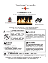
Woodbridge Fireplace Inc.
WARNING
Read the installation, operating and maintenance
instructions thoroughly before installing or servicing
this equipment.
Improper installation, adjustment, alteration, service,
or maintenance can cause injury or property damage.
DANGER
CARBON MONOXIDE
HAZARD
carbon
monoxide
which
has no odor.
Using it in an
enclosed space can kill you.
Never
use
this
appliance
in
an
enclosed space
as a
camper, tent,
car
or
home
.
Version française de ce manuel est disponible à partir du site WEB : www.woodbridgefp.com
French version of this Owners Manual is available at www.woodbridgefp.com
NATURAL GAS / PROPANE
OWNER’S O P ERATION AND INSTALLATION MANUAL
GLS-18(N,P), GLS-24(N,P)
Complies with:
ANSI Z21.60-2012 / CSA 2.26-2012 "Decorative Gas Appliances For Instalation In Solid-Fuel Burning Fireplaces ",
Report # 0401GL018S
18" and 24" GAS LOG SET
CGA 2.17-M91(R2014) "Gas Fired Appliances for Use at High Altitudes"
INSTALLER: Leave this manual with the appliance.
CONSUMER: Retain this manual for future reference.
NOTE: This appliance is not approved for
This appliance can produce
– Do not store or use gasoline or other flammable
vapors and liquids in the vicinity of this or any other
appliance.
department.
– Installation and service must be per formed
by a qualified installer, service agency or the
gas supplier.
•Do not touch any electrical switch; do not use any
phone in your building.
•Do not try to light any appliance.
•Immediately call your gas supplier from a neighbor's
phone. Follow the gas supplier's instructions.
•If you cannot reach your gas supplier, call the fire
mobile homes.
WARNING:
If the information in this manual is not
followed exactly, a fire or explosion may result causing
property damage, personal injury or loss of life.
WHAT TO DO IF YOU SMELL GAS
installation in bedrooms, bathrooms, or

TABLE OF CONTENTS
Safety Information
............................................. 3
Local Codes
........................................................ 4
Warranty Information .............................Back Cover
Gas Connection .................................................. 7
2
Specifications....................................................... 5
18" Logs Set Installation ...................................... 10
24" Logs Set Installation ...................................... 11
Lighting Instructions ...........................................
12
Operating Instructions ........................................ 14
Cleaning and Maintenance ................................ 15
Troubleshooting .................................................. 16
Illustrated Parts Breakdown, Parts List .............. 18
Locating Your Gas Log Set.................................. 6
To Turn Off Gas to Appliance .......................... 14
Burner Assembly Instructions .............................. 9

3
SAFETY INFORMATION
SAFETY
INFORMATION
Carbon Monoxide Poisoning:
Early signs of carbon monoxide
poisoning resemble the flu, with
headaches, dizziness, or nausea. If
properly. Get fresh air at once!
people are more affected by
carbon monoxide than others.
These include pregnant women,
people with heart or lung disease
or anemia, those under the
influence of alcohol, and those at
high altitudes.
Natural and Propane /LP Gas:
Natural and propane /LP gases are
odorless. An odor making agent is
added to the gas. The odor helps
you detect a gas leak. However,
the odor added to the gas can fade.
Gas may be present even though
no odor exists.
Make certain you read and under-
stand all warnings. Keep this
manual for reference. It is your
guide to safe and proper operation
1. This appliance, as supplied, is
only for use with the type of
gas indicated on the rating
plate.
2. If you smell gas:
•shut off gas supply
•do not try to light any appli-
ance
•do not touch any electrical
switch; do not use any phone
in your building
•immediately call to your gas
supplier from a neighbor’s
phone. Follow the gas
supplier’s instructions
•if you cannot reach your gas
supplier, call the fire depart-
ment
•in a recreational vehicle
•where curtains, furniture,
•in the high traffic areas
•in windy or drafty areas
4. Before installing in a solid
fuel burning fireplace, the
chimney flue and firebox
must be cleaned of soot,
creosote, ashes and loose
paint by a qualified chimney
cleaner. Creosote will ignite if
highly heated. Inspect chim-
ney flue for damage.
smokeless. If it ever appears
to smoke, turn off appliance
and call a qualified service
person. NOTE: During initial
operation, slight smoking
could occur due to unit curing
and the burning of
manufacturing residues.
6. To reduce the creation of soot,
follow the instructions in
Cleaning and Maintenance,
page 9.
7. Do not allow fans to blow
directly into the fireplace.
Avoid any drafts that alter
burner flame patterns, as it
could increase soothing.
8. Do not use a blower insert,
heat exchanger insert or other
accessory not approved for
outside air ventilation to run
properly.
10. Keep the appliance area clear
and free from combustible
materials, gasoline and other
flammable vapors and liquids.
11. Do not burn solid fuel in the
fireplace after installing the
appliance to cook food or
burn paper or other objects.
when in use. Keep children
and adults away from hot
surface to avoid burns or
will remain hot for a time
after shut-down. Allow
surface to cool before
touching.
13. Carefully supervise young
children when they are in the
14. Do not use appliance if any
part has been exposed to or
under water. Immediately call
a qualified service technician
to inspect the room appliance
and to replace any part of the
WARNING:
Any change
IMPORTANT: Read this
owner’s manual carefully
and completely before trying
to assemble, operate, or
Improper use of this unit can
cause serious injury or
death from burns, fire,
explosion, electrical shock,
and carbon monoxide
poisoning.
DANGER: Carbon mo-
noxide poisoning may lead
to death!
use with this Gas Log Set.
Gas Log Set. Do not use this
5. Gas Log Set is designed to be
9. This Gas Log Set needs fresh,
12. Gas Log Set becomes hot
clothing, or other flammable
objects are less than 42 inches
from the front, top, or sides of
the Log Set.
of this Log Set.
Log Set may not be working
you have these signs, the Gas
Have Gas Log Set serviced. Some
service this Gas Log Set.
3. Never install the Gas Log Set:
clothing ignition. The Log Set
room with the Gas Log Set.
WARNING: Keep flue
open when operating unit.
IMPORTANT: Fireplace
doors must be open when
appliance is operating.
to this Gas Log Set or its
controls can be dangerous.

4
SAFETY INFORMATION
control system and any gas
control which has been under
water.
cool before servicing,
installing, or repairing. Only a
qualified service person
should install, service, or
LOCAL CODES
care. Follow local codes. In the
absence of local codes, use the
latest edition of The National Fuel
Gas Code ANSZ223.1, also
known as NFPA 54 available
from:
•American National Standards
Institute, Inc., 1430
Broadway, New York,
NY 10018
•National Fire Protection
Association, Inc.,
Batterymarch Park, Quincy,
MA 02269.
15. Turn Gas Log Set off and let
repair the Gas Log Set.
Install and use the Gas Log Set with
State of Massachusetts: The installa-
tion must be made by a licensed plumber
or gas fitter in the Commonwealth of
Massachusetts.
Sellers of unvented propane or natural
gas-fired supplemental room heaters shall
provide to each purchaser a copy of 527
CMR 30 upon sale of the unit.
Vent-free gas products are prohibited for
bedroom and bathroom installation in the
Commonwealth of Massachusetts.
CAUTION: Do not remove
the metal data plates
These plates contain
important information.
NOTICE:
Installation, ser-
vice, and repair of this ap-
pliance must be performed
by a
qualified
install
er,
service agency, company or
gas supplier experienced
with this type of gas
appliances. Only factory
authorized components lis-
ted in this
instructi
on may
be u
sed in accordance with
the manufacturer’s
instruct
-
tions and all codes and
requirements of the autho-
rity having jurisdiction. Any
modifications to this
appli
-
ance
or use of unauthorized
items will void the manu-
facturer’s warranty,
and may
result in a hazardous
condition.
attached to the Gas Log set
.
components or accessory
WARNING: For installation in a solid-fuel burning fireplace only.
of not less than 50 square inches.
The fireplace chimney must have a permanent vent opening to atmosphere

Gas Type Natural Propane
Inlet Gas Pressure, MIN 5.0" w.c. 11.0" w.c.
Manifold Pressure 3.5" w.c. 10.0" w.c.
Inlet Gas Pressure, MAX 10.5" w.c. 13.0" w.c.
Gas Type Natural Propane
Inlet Gas Pressure, MIN 5.0" w.c. 11.0" w.c.
Manifold Pressure 3.5" w.c. 10.0" w.c.
Inlet Gas Pressure, MAX 10.5" w.c. 13.0" w.c.
Ignition Manual, with BBQ lighter Manual, with BBQ lighter
Gas Log Set Dimensions
(with logs installed) Width Depth Height
Model Width Depth Height Front Rear
29" 15" 18”
23" 14" 17”
Ignition Manual, with BBQ lighter Manual, with BBQ lighter
5
Heat Output, Btu/h 60,000 60,000
SPECIFICATIONS
Min. Fireplace Dimensions
GLS-18 Specifications
GLS-24 Specifications
Parameter / Model GLS-18N GLS-18P
Parameter / Model GLS-24N GLS-24P
SOLID FUEL FIREPLACE REQUIREMENTS
Heat Output, Btu/h 45,000 45,000
Orifice Size #26 #42
Shipping Weight, Lbs 125 125
Shipping Weight, Lbs 150 150
ROBERTSHAW Valve Model 711-811-404 711-811-404 CONVERTED
ROBERTSHAW Valve Model 711-811-404 711-811-404 CONVERTED
GLS-18
GLS-24
Orifice Size #30 #46
GAS LOG SET SPECIFICATIONS AND
30" 23" 16
"24
"
36" 24" 16
"26
"

6
NOTE:
This vented appliance
must be installed only in a solid-
fuel
burning fireplace with a
working flue and constructed of
The fireplace must include a
technical data related to proper
VENTING
SPECIFICATIONS FOR
INSTALLATION
The fireplace chimney flue and
vent must be drafting properly. To
check the vent for proper drafting:
Light a tightly rolled newspaper
on the end and place it at th
e
inside front edge of the fireplace.
Observe the smoke and be sure
the vent is properly drawing it up
the chimney. If the smoke spills
out into the room, extinguish the
flame and remove any obstruction
until proper venting is achieved.
INSTALLING DAMPER
CLAMP
Secure the damper stop clamp
provided to the leading edge of
the damper as shown
below
. If for
any reason this clamp doesn’t
work on your fireplace, another
suitable clamp or permanent stop
must be installed, or the damper
blade must be cut or removed.
CAUTION: Do not remove
the metal data plates
These plates contain
important information.
NOTICE:
Installation, ser-
vice, and repair of this ap-
pliance must be performed
by a
qualified
install
er,
service agency, company or
gas supplier experienced
with this type of gas
appliances. Only factory
authorized components lis-
ted in this
instructi
on may
be u
sed in accordance with
the manufacturer’s
instruct
-
tions and all codes and
requirements of the autho-
rity having jurisdiction. Any
modifications to this
appli
-
ance
or use of unauthorized
components or accessory
items will void the manu-
facturer’s warranty,
and may
result in a hazardous
condition.
WARNING: Before
install
-
ling in a solid fuel burning
fireplace, the chimney flue
and firebox must be cleaned
of soot, creosote, ashes
and
loose paint by a qualified
chimney cleaner. Creosote
will ignite if highl
y heated. A
dirty chimney flue may
create and distribute soot
within the house. Inspect
chimney flue for damage.
attached to the Log Set
.
installation of the vented Log Set
is attempted
.
are applicable before
install
ation
LOCATING YOUR GAS LOG SET
noncombustible material.
working flue and venting system
with minimum opening 50 sq. in.
Make sure that the following

(Propane/LP Only)
CHECK GAS TYPE
INSTALLING GAS PIPING TO FIREPLACE / BURNER SYSTEM LOCATION
INSTALLATION ITEMS NEEDED
Before installing replace and burner system, make sure you have the items listed below.
• External regulator (supplied by installer) • Piping (check local codes) • Sealant (resistant to propane/LP gas)
• Equipment shutoff valve* • Test gauge connection* • Sediment trap (recommended)
• Tee joint • Pipe wrench
• approved exible gas line with gas connector (if allowed by local codes — not provided)
* A CSA design-certied equipment shutoff valve with 1/8" NPT tap is an acceptable alternative to test gauge connection.
Purchase the CSA design-certied equipment shutoff valve from your dealer.
For propane/LP connections only, the installer must supply an external regulator. The external regulator will reduce incoming
gas pressure. You must reduce incoming gas pressure to between 11 and 13 inches of water. If you do not reduce incoming gas
pressure, burner system regulator damage could occur. Install external regulator with the vent pointing down as shown in Figure
External
Regulator
100 lb. (min)
Propane/LP
Supply Tank
Vent Pointing
Down
When using copper or ex connectors use only ttings approved
for gas connections. The gas control inlet is
A qualified installer or service person must
connect appliance to gas supply. Follow all
local codes.
WARNING
For propane/LP units, never connect fireplace directly to the propane/LP supply. This
burner system requires an external regulator (not supplied). Install the external regulator
between the burner system and propane/LP supply.
CAUTION
Use only new black iron or steel pipe. Internally
tinned copper or copper tubing can be used per
National Fuel Code, section 2.6.3, providing gas
meets hydrogen sulfide limits, and where permitted
by local codes. Gas piping system must be sized
to provide minimum inlet pressure (listed on data
plate) at the maximum flow rate (BTU/hr). Undue
pressure loss will occur if the pipe is too small.
CAUTION
1/2" NPT.
2. Pointing the vent down protects it from freezing rain or sleet.
Figure 2 - External Regulator with Vent Pointing Down
7
GAS CONNECTION
Use proper gas type for the Log Set you are installing. If you have conicting gas type, do not install replace. See dealer where
you purchased the Log Set for proper replace for your gas type or conversion kit.

A.G.A. Design-Certified
Manual Shutoff Valve
With 1/8” NPT Tap
Cap Pipe Nipple Tee Joint
Sediment Trap
3” Minimum
CONNECTING TO GAS
SUPPLY
Installation Items Needed
pliers
-sediment trap
-tee joints
-pipe wrench
Installation must include a manual
shutoff valve, union, and plugged
1/8” NPT tap. Locate NPT tap
within reach for test gauge hook
up. NPT tap must be upstream
from the appliance.
Apply pipe joint sealant lightly to
male threads. This will prevent
excess sealant from going into
pipe. Excess sealant in pipe could
result in a clogged burner injector.
Install sediment trap in supply line
as shown below. Locate sediment
trap where it is within reach for
cleaning and trapped matter is not
likely to freeze. A sediment trap
CHECKING GAS
CONNECTION
Test Pressures in Excess Of
1/2 psi (3.5 kPa)
Test Pressures Equal To or
Less Than 1/2 psi (3.5 kPa)
WARNING:
A qualified
service person must con-
nect appliance to gas sup-
ply. Follow all local codes.
CAUTION:
Use only new,
black iron or steel pipe.
Internally tinned copper
tubing may be used in
certain areas. Use pipe of
1/2" diameter or greater to
allow proper gas volume to
WARNIN
G:
Test all gas
piping and connections for
leaks after installing or
servicing. Correct all leaks
at once.
WARNING:
Never use an
open flame to check for a
leak. Apply a mixture of
liquid soap and water on all
joints. Bubbles forming
show a leak. Correct all
leaks at once.
From Gas Meter
(5” W.C. to 10.5” W.C.
pressure)
The appliance and its individual
shutoff valve must be discon-
nected from the gas supply piping
system during any pressure testing
of that system at test pressures in
excess of ½ psi (3.5 kPa).
The appliance must be isolated
from the gas supply piping system by
closing its individual manual
shutoff valve during any pressure
testing of the gas supply piping
system at test pressures equal to or
less than ½ psi (3.5 kPa).
Approved Flexible
Gas
Connector
IMPORTANT
This appliance is not designed
for use with a non-disposable,
self-contained LP-gas supply
system! Do not use a gas hose
to connect the appliance to any
gas supply. Use approved
Flexible Gas Connectors.
items listed bellow:
-piping (check local codes)
-sealant
-manual shutoff valve
-adjustable (crescent) wrench or
traps moisture and contaminants.
This keeps them from going into
If sediment trap is not installed or
is installed wrong, unit may not
run properly.
GAS CONNECTION
8
Log Set, make sure you have all
the Gas Log Set. If pipe is too
small, undue loss of pressure
will occur.
Indoor Log Set cont rols.
Before installing the

2.
Position the burner assembly centered from side to side and as far toward the back wall of the fireplace as
DO NOT DROP ANY LOG PART AS BREAKAGE MAY EASILY OCCUR.
MAY EASILY OCCUR.
1 . Carefully remove all parts from the box and inspect them for any damage. Read the Certification Tag attached.
4.
SOURCE TO CHECK FOR LEAKS. Any leaks must be corrected before proceeding with the installation.
3. Connect the gas line to the 1/2" flex connector of the Log Set using supplied shut-off valve (see "Fireplace
Installation").
and then watch for air bubbles indicating leaks. DO NOT USE A FLAME OR ANY TYPE OF IGNITION
C arefully remove all log parts from the box and place them onto the floor off to one side of the fireplace.
possible.
9
BURNER ASSEMBLY INSTRUCTIONS
6.
Make sure the gas connections are tight. Turn on the gas and coat each joint with a soap and water solution
5. Test functionality of the Log Set burner (see "Operating Instructions") before placing logs.
Make sure the flame is tall, steady, and yellow. Ignition time should not exceed 5-7 seconds.
Remove grate from the box and place onto the base with rear legs positioned inside of support brackets.
7.
DO NOT REMOVE ANY LOGS FROM ORIGINAL PACKAGING TILL STEP # 7 AS BREAKAGE
Fill the burner tray with the supplied glass media. Make sure the burner is completely covered with
8. Carefully position logs over the burner grate. Start with placing the largest Log #1 behind the rear set of
vertical tabs welded on the grate. Then place large Logs #2 and #3 in front of the nearest row of the vertical
front and rear logs.
Continue with the rest of the logs following the recommended positioning shown on the next page(s).
of the fireplace.
Remove the burner assembly from the box and place it onto floor of your fireplace with grate facing front
tabs welded on the grate. Make sure all three logs are secured on the grate with appropriate gap between
the media and the pilot is not blocked with loose pieces of glass. Place small (approximately 1/2" dia.) pieces
of supplied amber material over the glass bed covering the burner area completely as shown on the
photograph.
WARNING
within the appliance.
Do not operate the appliance without the burner being completely filled with glass media.
Lighting the burner without the glass media will cause unsafe temperatures

10
6
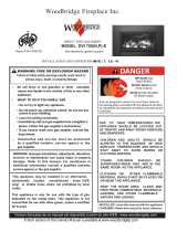
18" LOG SET INSTALLATION
1
23
45
65
4
3
2
1
LOG PLACEMENT
GLO-18 LOG SET
WARNING: Failure to position
the parts in accordance with
these diagrams or failure to
use only parts specially
approved with this appliance
may result in property
damage or personal injury.

11
24" LOG SET INSTALLATION
11
GLS -24 LOG SET
1
2
3
4
5
6
7
LOG PLACEMENT
1
2
3
4
5
6
7

32 L100001
A.This apliance is equiped with a pilot which must be lit by hand while following these instructions exactly.
B. BEFORE OPERATING smell all around the appliance area for gas. Be sure to smell next to the oor because
some gas is heavier than air and will settle on the oor.
WHAT TO DO IF YOU SMELL GAS:
•Do not try to light any appliance.
•Do not touch any electric switch; do not use any phone in your building.
•Immediately call your gas supplier from a neighbor's phone.
Follow the gas supplier's instructions.
•If you cannot reach your gas supplier, call the fire department.
C. Use only your hand to push in, or turn the gas control knob. Never use tools. If the knob will not push in or
turn by hand, don't try to repair it. Call a qualied service technician. Force or attempted repair may result in
a re or explosion.
D. Do not use this appliance if any part of it has been under water. Immediately call a qualied service technician
to inspect the appliance and to replace any part of the control system and any gas control that has been under
water.
FOR YOUR SAFETY READ BEFORE LIGHTING
LIGHTING PILOT FOR THE FIRST TIME
INITIAL LIGHTING
Purge air from the supply line as follows:
• Open main shutoff valve.
• Unscrew main pressure test point.
• Leave inlet test screw open until gas comes in.
• When gas is owing, tighten inlet screw immediately.
LEAK TESTING
1. Follow the pipe from the gas supply line connection to the gas valve. Check connection for leaks with soap
and water mixture.
2. Next check for gas leaks at the burner with soap and water mixture.
3. Check the pilot for gas leaks with soap and water mixture.
If you do not follow these instruction exactly,
a fire or explosion may result causing property
damage, personal injury or loss of life.
WARNING
Never use an open flame to check for gas leak.
DANGER
12
LIGHTING INSTRUCTIONS

L100001 35
APPROVED LEAK TESTING METHOD
You may check for gas leaks with the following methods only:
• Soap and water solution
• An approved leak testing spray
• Electronic sniffer
NOTE: Remove any excessive pipe compound from
the connections. Excessive pipe compound can set
off electronic sniffers.
LIGHTING INSTRUCTIONS
Check for gas leaks in each of the following locations:
• Pipe from the gas supply line connection to the gas valve
•Burner connections, pilot • Field made joints / gas shutoff valve
•All joints on valve and control body • Factory made joints, each joint and connection
LIGHTING PILOT FOR THE FIRST TIME
If using a soap and water solution to test
for leaks, DO NOT spray solution onto
control body.
WARNING
Never use an open flame to check for gas leak.
DANGER
WARNING
13
LIGHTING INSTRUCTIONS
Light pilot with a match or barbeque lighter.
Keep knob fully depressed for
WA
1. STOP! Read the safety information on previous page.
• If the pilot does not stay lit, repeat steps 1 and 2.
• If the pilot knob does not pop up when released, STOP and immediately call service technician or gas supplier
• If the pilot will not stay lit after several tries, turn the gas control knob to "OFF" position
and call your service technician or gas supplier.
Pilot Position
Follow "B" in the safety information on the previous page. If you don't smell gas, go to the next step.
_____
Pilot Assembly
Release and check that pilot continues to burn.
a few seconds.
Off Position
2. Turn the gas control knob to the "OFF" position.
3. Wait five (5) minutes to clear out any gas. If you then smell gas, STOP!
4. Locate the Pilot Assembly on the back of Gas Log Set.
5. Depress and turn pilot gas knob counterclockwise to "PILOT" position.
6.Depress fully and hold pilot gas knob.

34 L100001
T
LIGHTING BURNER
PILOT POSITION
TO TURN OFF GAS TO APPLIANCE
Off Position
Pilot Position
The “ON/REMOTE/OFF” switch for the main burner can be found
turn on and to turn off the main burner without using the gas valve
LIGHTING THE BURNER
1. Depress and turn knob clockwise to “OFF” position.
14
LIGHTING INSTRUCTIONS
On Position
maintaining the pilot light.
Depress and turn knob to pilot position to keep burner off while
Remote Position
MAIN BURNER SWITCH / REMOTE
position. It will take less than four (4) seconds for the burner to ignite.
Depress and turn the knob counterclockwise to the “ON”
on remote control receiver beneath the base.This switch allo ws you to
knob.
Make sure the button is in the "REMOTE" position to operate the main
to operate the burner manually without remote control.
burner using a hand held remote. Slide the switch to "ON" or "OFF" position

Pilot Flame
BURNER, PILOT AND CONTROL COMPARTMENT
Keep the control compartment clean by vacuuming or brushing at least twice a year.
Make sure the burner porting, pilot air opening and burner air opening are free of obstructions at all times.
PILOT FLAME
The ames from the pilot should be visually checked as soon as the unit is installed
and periodically during normal operation. The pilot ame must always be present
when the replace is in operation. The pilot ame has two distinct flames, one
engulng the thermopile and the other reaching to the main burner.
BURNER
Inspect area around the injector. Remove any lint or foreign material with a brush
or vacuum.
Turn off gas before servicing fireplace. It
is recommended that a qualified service
technician perform these check-ups at the
beginning of each heating season.
WARNING
15
CLEANING AND MAINTENANCE
Have the venting system of the solid fuel burning fireplace inspected and cleaned
annually by a qualified agency.
VENTING SYSTEM

and let cool before servicing. Only
a qualified service person should
service and repair this appliance.
1. Poor fuel quality
age
1. Passage of air/gas across irregular sur-
faces
2. Excessive gas pressure on natural gas
units
1. Incorrect gas supply or pressure
2. Blocked burner orifice or burner mani-
fold ports
3. Improper burner orifice size
1. Battery is not installed. Battery power
is low
Unit is smoking / sooting excessively
(
Note:
It is natural and unavoidable for
appliance sets to produce moderate
levels of carbon (soot) where flames
contact the media. This is especially
true with propane/LP gas.)
Burner is excessively noisy
(
Note:
The movement and combustion of
gas will create low, unavoidable levels of
noise.)
Burner flame is too low or too high
Remote does not function
1. Contact local natural or propane/LP gas
company
passage
flame pattern and/or check for proper
1. Relieve any tight bends or kinks in gas
supply line
2.Check/reset gas regulator pressure
1. Check for proper gas supply pressure
2. Free burner orifice and manifold ports
1.Replace batteries in receiver and
Note:
All troubleshooting items are listed in
order of operation.
OBSERVED PROBLEM POSSIBLE CAUSE REMEDY
burner tube.
orifice sizing.
covered with glass media.
of any burrs, paint, or other blockage
i.e. spider webs, etc.
remote control. Re-program the receiver.
2. Excessive flame impingement or block-
3.Improper fuel/air mixture 3.Remove any foreign items from the
4. Not enough media over 4. Make sure the burner tube is completely
2.Separate the logs to allow more flame
3. Verify proper burner orifice sizing
WARNING:Turn off appliance
WARNING: If you smell gas
• Shut off gas supply.
• Do not try to light any appliance.
• Do not touch any electrical switch; do not use any phone in
your building.
• Immediately call your gas supplier from a neighbor’s phone.
Follow the gas supplier’s instructions.
• If you cannot reach your gas supplier, call the fire department.
Pilot lights but flame goes out when control
knob is released
Burner does not light after pilot is lit
1. Press in control knob fully
2. After pilot lights, keep control knob
pressed in 30 seconds
3. Fully open manual shut-off valve
4. A) Contact local natural gas company
B) Clean pilot (see Cleaning and Mainte-
nance, page 10) or replace pilot assembly
5. Hand tighten until snug, then tighten
1/4 turn more
6.Replace thermopile
7. Replace control valve
1. Clean burner orifice
2. Contact local natural or propane/LP gas
company
3. Replace burner orifice
4. Reconnect leads
1. Control knob not fully pressed in
2. Control knob not pressed in long enough
3. Manual shutoff valve not fully open
4.Pilot flame not touching thermopile,
which allows thermopile to cool,
causing pilot flame to go out. This prob-
lem could be caused by one or both of
the following:
A) Low gas pressure
B) Dirty or partially clogged pilot
5.Thermopile connection loose at con-
trol valve
6.Thermopile damaged
7. Control valve damaged
1. Burner orifice clogged
2. Inlet gas pressure is too low
3. Burner orifice diameter is too small
4.Thermopile leads disconnected or im-
properly connected
16
TROUBLESHOOTING

POSSIBLE CAUSE
1.Unit burning vapors from paint, hair
spray, glues, cleaners, chemicals, new
2. Control valve defective
OBSERVED PROBLEM
Gas odor even when control knob is in OFF
position
Gas odor during combustion
REMEDY
1. Open flue to maximum. Stop using odor
causing products while unit is running
2. Locate and correct all leaks (see Check-
1. Locate and correct all leaks (see Check-
2. Replace control valve
1. Locate and correct all leaks (see Check-
Gas Log Set produces unwanted odors
carpet, etc.
2. Gas leak. See
previous page
1. Gas leak. See Warning statement on
previous page
1. Gas leak. See Warning statement on
previous page
17
TROUBLESHOOTING
IMPORTANT:
Operating unit where impurities in air exist may create odors.
Cleaning supplies, paint, paint remover, cigarette smoke, cements and glues, new
carpet or textiles, etc., create fumes. These fumes may mix with combustion air
and create odors. These odors will disappear over time.
Warning statement on ing Gas Connections, page 8)
ing Gas Connections, page 8)
ing Gas Connections, page 8)

1
2
3
4
5
8
9
10
11
FOR PART DESCRIPTION
12
6
7
13
13
14
ILLUSTRATED PARTS LIST
18
SEE NEXT PAGE
OPTIONAL STAINLESS STEEL BURNER SHOWN
15

All replacement parts should be ordered from your installer or from
Woodbridge Fireplace Inc.
QT.
Y
KEY PART NUMBER
10 D300090 D300090 SUPPLIED 1/2" SHUTOFF VALVE 1
12 PCB-R PCB-R SKYTECH REMOTE RECEIVER 1
11 PCB PCB SKYTECH REMOTE CONTROL 1
14 G100050 G100050 BURNER GLASS MEDIA, Lbs. 10
9 D300098 D300098 1/2" X 12" FLARE GAS CONNECTOR 1
8 C100038 C100038 5/16" X 7" FLEX CONNECTOR 1
5 R100020 R200020 MAIN GAS VALVE 1
3 W200211 W200211 GRATE 1
2 F200221 F200221 BASE 1
1 W200218 W200218 BURNER ASSEMBLY 1
QT.
Y
KEY PART NUMBER
10 D300090 D300090 SUPPLIED 1/2" SHUTOFF VALVE 1
12 PCB-R PCB-R SKYTECH REMOTE RECEIVER 1
11 PCB PCB SKYTECH REMOTE CONTROL 1
9 D300098 D300098 1/2" X 12" FLARE GAS CONNECTOR 1
8 C100038 C100038 5/16" X 7" FLEX CONNECTOR 1
5 R100020 R200020 MAIN GAS VALVE 1
1 W200208 W200208 BURNER ASSEMBLY 1
2 F200220 F200220 BASE 1
3 W200210 W200210 GRATE 1
7 F300072 F300073 ORIFICE (NG) / AIR MIXER (LP) 1
13 M100508 M100508 7 PC. LOG SET 1
14 G100050 G100050 BURNER GLASS MEDIA, Lbs. 15
ILLUSTRATED PARTS LIST
19
GLS-18" LOG SET
NO. GLS 18-N GLS 18-P DESCRIPTION
GLS-24" LOG SET
NO. GLS 24-N GLS 24-P DESCRIPTION
This list contains replaceable parts used in your indoor Gas Log Set.
7 F300074 F300075 ORIFICE (NG) / AIR MIXER (LP) 1
13 M100509 M100509 6 PC. LOG SET 1
15 F100037 F100037 DAMPER CLAMP 1
15 F100037 F100037 DAMPER CLAMP 1
6 F200222 F200222 GAS VALVE BRACKET 1
4 R100042 R200042 VENT-FREE PILOT ASSEMBLY 1
6 F200222 F200222 GAS VALVE BRACKET 1
4 R100022 R200022 PILOT ASSEMBLY 1
at
1-905-564-3001 or on-line at www.woodbridgedealer.com

LIMITED LIFETIME WARRANTY POLICY
LIFETIME WARRANTY
FIVE YEAR WARRANTY
BASIC WARRANTY
Woodbridge Fireplace Inc. warrants the components and materials in your gas appliance to be free from manufacturing and
material defects for a period of two years from date of installation. After installation, if any of the components manufactured by
Woodbridge Fireplace Inc. in the appliance are found to be defective in materials or workmanship, Woodbridge Fireplace Inc.
will, at its option, replace or repair the defective components at no charge to the original owner. Woodbridge Fireplace Inc. will
also pay for reasonable labor costs incurred in replacing or repairing such components for a period of two years from date of
installation. Any products presented for warranty repair must be accompanied by a dated proof of purchase.
This Limited Lifetime Warranty will be void if the appliance in not installed by a qualied installer in accordance with the instal-
lation instructions. The Limited Lifetime Warranty will also be void if the appliance is not operated and maintained according to
the operating instructions supplied with the appliance, and does not extend to (1) rebox/burner assembly damage by accident,
neglect, misuse, abuse, alterations, negligence of others, including the installation thereof by unqualied installers, (2) the costs
of removal, reinstallation or transportation of defective parts on the appliance, or (3) incidental or consequential damage. All
service work must be performed by an authorized service representative.
This warranty is expressly in lieu of other warranties, express or implied, including the warranty of merchantability of tness for
purpose and of all other obligations or liabilities. Woodbridge Fireplace Inc. does not assume for it any other obligations or liabili-
ties in connection with sale or use of the appliance. It states that do not allow limitations on how long an implied warranty lasts,
or do not allow exclusion of indirect damage, those limitations of exclusions may not apply to you. You may also have additional
rights not covered in the Limited Lifetime Warranty.
Woodbridge Fireplace Inc. reserves the right to investigate any and all the claims against the Limited Lifetime Warranty and
decide upon method of settlement.
For information about this warranty, contact:
The following components are warranted for life to the original owner, subject to proof of purchase: Base, Grate, and Steel Burner.
The following components are warranted ve (5) years to the original owner, subject of proof of purchase: Ceramic Logs.
Woodbridge Fireplace Inc.
Ontario, Canada L5T 1C9
Tel.: 1-905-564-3001
www.woodbridgedealer.com
1305 Meyerside Dr., Mississauga
REV. 11.2018
/