
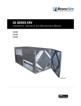
GH Rooftop Series shown
GH-Series for Indoor and Outdoor Commercial Applications
GH SERIES Indirect Gas-Fired Duct Furnace
Installation, Operation and Maintenance Manual
GH Indoor Series shown

1.800.627.44992
GH-Series Indirect Gas-Fired Duct Furnace
ACCESSORY
WARNING AVERTISSEMENT
Do not store or use gasoline or other flammable vapors and
liquids in the vicinity of this or any other appliance.
WHAT TO DO IF YOU SMELL GAS
u Do not try to light any appliance.
u Do not touch any electrical switch; do not use any phone
in your building.
u Leave the building immediately.
u Immediately call your gas supplier from a phone remote
from the building. Follow the gas supplier’s instructions.
u If you cannot reach your gas supplier, call the fire depart-
ment.
Installation and service must be performed by a qualified
installer, service agency or the gas supplier.
Ne pas entreposer ni utiliser d’essence ou autre vapeurs ou
liquides inflammable à proximité de cet appareil ou de tout
autre appareil.
QUE FAIRE SI VOUS SENTEZ UNE ODEUR DE GAZ
u Ne tentez pas d’allumer un appareil.
u Ne touchez pas à un interrupteur; n’utilisez pas de télé-
phone dans l’édifice où vous vous trouvez.
u Sortez de l’édifice immédiatement.
u Appelez immédiatement le fournisseur de gaz à par-
tir d’un téléphone à l’exterieur de l’édifice. Suivez les
instructions du fournisseur de gaz.
u Si vous ne pouvez joindre le fournisseur de gaz, appelez
les pompiers.
L’installation at les réparations doivent être confiées à un
installateur qualifié ou au fournisseur de gaz.
WARNING AVERTISSEMENT
ARC FLASH AND ELECTRIC SHOCK HAZARD
Arc flash and electric shock hazard. Disconnect all electric
power supplies, verify with a voltmeter that electric power
is off and wear protective equipment per NFPA 70E before
working within electric control enclosure. Failure to comply
can cause serious injury or death.
Customer must provide earth ground to unit, per NEC, CEC
and local codes, as applicable.
Before proceeding with installation, read all instructions,
verifying that all the parts are included and check the
nameplate to be sure the voltage matches available utility
power.
The line side of the disconnect switch contains live
high-voltage.
The only way to ensure that there is NO voltage inside the
unit is to install and open a remote disconnect switch and
verify that power is off with a volt meter. Refer to unit elec-
trical schematic.Follow all local codes.
RISQUE FLASH D’ARC ET DE CHOC ÉLECTRIQUE
Risque d’arc êlectrique et de choc électrique. Débrancher
toutes les alimentation électrique, vérifier avec un voltmètre
que l’alimentation électrique est coupée et portez des vête-
ments de protection conformément à la norme NFPA 70E
avant de travailler dans la console de commande électrique.
Le non-respect peut entraîner des blessures graves ou la
mort.
Le client doit fournir la terre à l’unité, selon les codes NEC,
CEC et locaux, selon le cas.
Avant de procéder à l’installation, lisez toutes les instruc-
tions, vérifiez que toutes les pièces sont incluses at vérifier
la plaque signalétique pour vous assurer que la tension
correspond à la puissance disponible du réseau.
Le côté entrée du sectionneur contient une haute tension
active.
La seule façon de s’assurer qu’il n’y a pas de tension à
l’intérieur de l’unité est d’installer et d’ouvrir un interrupteur
de déconnexion à distance et de vérifier que l’alimentation
est coupée à l’aide d’un voltmètre. Référe-vous au schéma
électrique de l’appareil.
Suivez tous les codes locaux.
WARNING
RISK OF FIRE OR EXPLOSION
Do not install duct furnace where it may be exposed to poten-
tially explosive or flammable vapors!
Do not store or use gasoline or other flammable vapors and
liquids in the vicinity of this or any module.
Do not install in potentially explosive atmosphere laden with
dust, sawdust or similar products.
AVERTISSEMENT
RISQUE D’INCENDIE OU D’EXPLOSION
N'installez pas le four à condoits là oùil peut être exposé à des
vapeurs potentiellement explosives ou inflammables.
Ne stockez pas et n'utilisez pas d'essence ou d'autres vapeurs
et liquides inflammables à proximité de ce module ou de tout
autre module. Ne pas installer dans une atmosphère potentiel-
lement explosive chargée de poussière, de sciure de bois ou de
produits similaires.

31.800.627.4499
GH-Series Indirect Gas-Fired Duct Furnace ACCESSORY
CAUTION ATTENTION
IMPORTANT
ATTENTION
ATTENTIONCAUTION
CAUTION
RISK OF ELECTRIC SHOCK OR EQUIPMENT DAMAGE.
Whenever electrical wiring is connected, disconnected
or changed, the power supply to the module and module
controls must be disconnected. Lock and tag the disconnect
switch or circuit breaker to prevent accidental reconnection
of electric power.
RISQUE DE CHOC ELECTRIQUE OU DE DOMMAGE
D'APPAREIL
Chaque fois que le câblage électrique est connecté, décon-
necté ou changé, l'alimentation électrique du module et des
commandes du module doit être déconnectée. Verrouillez
et étiquetez le sectionneur ou le disjoncteur pour éviter une
reconnexion accidentelle de l'alimentation électrique.
Cet équipement doit être installé en suivant les meilleures
pratiques de l'industrie et tous les codes applicables. Tout
dommage aux composants, aux assemblages, aux sous-en-
sembles ou à l'armoire qui est causé par des pratiques d'instal-
lation incorrectes annulera la garantie.
L'installation du câblage doit être conforme aux codes du
bâtiment locaux. En l'absence de codes de construction locaux,
l'installation doit être conforme au Code national de l'électricité
ANSI/NFPA 70 - dernière édition. L'unité doit être mise à la
terre électriquement conformément à ce code. Au Canada,
le câblage doit être conforme à la norme CSA C22.1 du Code
Canadien de l'électricité.
N'installez pas les appareils dans des endroits où les produits
de combustion peuvent être aspirés dans les ouvertures de
bâtiment adjacentes, comme les fenêtres, les prises d'air frais,
etc.
La distance entre le terminal de ventilation et les allées
publiques adjacentes, les bâtiments adjacents, les fenêtres
ouvrantes et les ouvertures de bâtiment doivent être conformes
aux codes locaux. En l'absence de codes locaux, l'installation
doit être conforme au Code national du gaz combustible, à la
norme ANSI Z223.1 ou aux codes d'installation Canadiens CAN
/ CGA B-149.
Do not install units in locations where flue products can be
drawn into adjacent building openings such as windows, fresh
air intakes, etc. Distance from vent terminal to adjacent public
walkways, adjacent buildings, operable windows and building
openings shall conform with the local codes. In the absence of
local codes, installation shall conform with the National Fuel Gas
Code, ANSI Z223.1 or the Canadian CAN/CGA B-149
Installation Codes.
Installation of wiring must conform with local building codes. In
the absence of local building codes, installation must conform
to the National Electric Code ANSI/NFPA 70 - Latest Edition.
Unit must be electrically grounded in conformance with this
code. In Canada, wiring must comply with CSA C22.1, Canadi-
an Electrical Code.
NOTICE
This equipment is to be installed by following Industry Best
Practices and all applicable codes. Any damage to
components, assemblies, subassemblies or the cabinet which
is caused by improper installation practices will void the
warranty.
NOTE: See additional cautions
and warnings in Section 7, Gas
Piping Installation.
REMARQUE: Voir les mises en
garde et les avertissements
supplémentaires de la Section 7,
Installation de Tuyauterie de Gaz.

1.800.627.44994
GH-Series Indirect Gas-Fired Duct Furnace
ACCESSORY
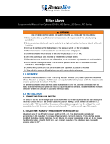
Record information as shown below. In the unlikely event that factory assistance is ever
required, this information will be needed.
Serial Number:
Furnace Model No:
Furnace Turndown: Single Stage
Two-Stage
Modulated 5:1
Modulated 10:1
Locate the RenewAire unit label, found inside the removable panel on the furnace.
NOTE: This information is for purposes of identifying the specific furnace. Unit-specific option
data can then be obtained, as needed, from the Model Number. See Gas Furnace Code in this
manual for further details.
TYPICAL UNIT LABEL (FOUND INSIDE THE
REMOVABLE PANEL ON THE FURNACE)
SAVE THIS MANUAL
UNIT RECORDS
OWNER INFORMATION
NOTE: This page is
to be completed by
the installing con-
tractor. The com-
pleted document is to be
turned over to the owner
after start-up.

51.800.627.4499
GH-Series Indirect Gas-Fired Duct Furnace ACCESSORY
TABLE OF CONTENTS
1.0 OVERVIEW 10
1.1 DESCRIPTION .......................................................10
1.2 GAS SUPPLY ......................................................... 10
1.3 ELECTRICAL SUPPLY .............................................10
1.4 INPUT CAPACITY IN MBH ......................................10
1.5 GAS FURNACE MODULATION (TURNDOWN) ...........11
1.6 SINGLE AND MULTIPLE
FURNACE CONFIGURATIONS .................................14
1.7 USER INTERFACE .................................................14
2.0 VENTING 15
2.1 EQUIVALENT LENGTH ............................................15
2.2 INDOOR FURNACE VENTING ..................................15
2.3 OUTDOOR FURNACE VENTING ...............................19
3.0 GAS SUPPLY 20
4.0 PLACEMENT RECOMMENDATIONS 21
5.0 DUCTWORK 21
6.0 COMPONENT TECHNICAL DATA 24
6.1 PERFORMANCE DATA ..........................................24
6.2 FURNACE SIZE SELECTION ...................................25
6.3 MAXIMUM AND MINIMUM AIRFLOWS ....................26
6.4 DUCT FURNACE PRESSURE DROP .........................26
6.5 DIMENSIONED DRAWINGS ....................................27
6.6 GAS TRAIN SCHEMATICS ......................................28
6.7 GAS VALVE ILLUSTRATIONS ..................................29
6.8 ELECTRICAL DATA ................................................31
6.9 ELECTRICAL SCHEMATICS ....................................32
7.0 FURNACE INSTALLATION 40
7.1 FURNACE INSPECTION ON ARRIVAL ......................40
7.2 PREPARING FOR INSTALLATION ............................40
7.3 INSTALLATION CODES ..........................................40
7.4 PLACEMENT OF FURNACE ....................................40
7.5 CLEARANCE TO COMBUSTIBLES AND SERVICE
CLEARANCES .......................................................41
7.6 FURNACE INSTALLATION REQUIREMENTS .............41
7.7 INSTALL CONTROL SENSORS ................................ 42
7.8 INSTALL GAS SUPPLY PIPING ................................42
7.9 CONNECT CONDENSATE DRAIN .............................44
7.10 MAKE ELECTRICAL CONNECTIONS ......................44
8.0 OPERATING INSTRUCTIONS 45
8.1 START-UP ............................................................. 45
8.2 INLET GAS PRESSURE ..........................................45
8.3 INPUT ..................................................................45
8.4 MANIFOLD PRESSURE ADJUSTMENT ....................45
8.5 FAILURE TO IGNITE ...............................................46
8.6 UNIT START-UP ADJUSTMENTS ............................46
8.6.1 Burner Flames ..................................................................46
8.6.2 Shutdown After Unit Start-Up............................................47
8.6.3 Normal Operation .............................................................47
9.0 MAINTENANCE 48
9.2 FURNACE MODULE OPERATION CHECK .................48
9.3 SERVICE PARTS .................................................... 49
10.0 TROUBLESHOOTING 50
10.1 SEQUENCE OF OPERATIONS (SOO) ......................50
10.2 IGNITION CONTROLLER ....................................... 50
12.0 WARRANTY 51

1.800.627.44996
GH-Series Indirect Gas-Fired Duct Furnace
ACCESSORY
TABLE OF ILLUSTRATIONS
TABLE OF CONTENTS
Figure 1.5.0 Chart of Available Turndown Options by Furnace Model ................................................. 12
Figure 1.5.1 Typical Installation of Indoor Separate Inlet Exhaust Furnace ......................................... 13
Figure 1.5.2 Typical Installation of Indoor Top Exhaust Furnace ......................................................... 13
Figure 1.5.3 Typical Installation of Outdoor Top Exhaust Furnace ...................................................... 13
Figure 1.5.4 Typical Parallel Furnace Installation .............................................................................. 13
Figure 1.5.5 Typical Factory-Provided Connection Points .................................................................. 13
Figure 1.6.0 Single Unit—Top View .................................................................................................. 14
Figure 1.6.1 Parallel Unit—Top View ................................................................................................ 14
Figure 2.2.0 Indoor Vertical Venting ................................................................................................. 16
Figure 2.2.1 Indoor Horizontal Venting .............................................................................................. 17
Figure 2.2.2 Vertical Venting—Separate Combustion ....................................................................... 18
Figure 2.2.3 Horizontal Venting—Separate Combustion ................................................................... 18
Figure 2.3.0 Outdoor Horizontal Venting ........................................................................................... 19
Figure 2.3.1 Outdoor Vertical Venting ............................................................................................... 19
Figure 3.0.0 Example of Multiple Furnace Supply Gas Piping ............................................................20
Figure 5.0.0 Ductwork Configuration Example A ...............................................................................22
Figure 5.0.1 Ductwork Configuration Example B ............................................................................... 22
Figure 5.0.2 Ductwork Configuration Example C ...............................................................................23
Figure 5.0.3 Ductwork Configuration Example D ...............................................................................23
Figure 6.1.0 50–200 MBH Temperature and Pressure Chart.............................................................. 24
Figure 6.1.1 250–400 MBH Temperature and Pressure Chart ............................................................24
Figure 6.5.0 Dimensioned Drawings of Duct Furnaces ..................................................................... 27
Figure 6.6.0 Example of Single Stage and Two-Stage Gas Train ........................................................28
Figure 6.6.1 Example of Modulated Gas Train ................................................................................... 28
Figure 6.7.0 Single Stage Gas Valves (typical) ..................................................................................29
Figure 6.7.1 Two-Stage Gas Valves (typical) .....................................................................................29
Figure 6.7.2 Modulating Gas Valves (typical) .....................................................................................30
Figure 6.9.0 Control Wiring, 1-Stage Furnace ...................................................................................32
Figure 6.9.1 Control Wiring, 2-Stage Furnace ................................................................................... 33
Figure 6.9.2 Control Wiring, 5:1 Turndown Furnace, 50–100 MBH ....................................................34
Figure 6.9.3 Control Wiring, 5:1 Turndown Furnace, 125–175 MBH ...................................................35
Figure 6.9.4 Control Wiring, 10:1 Turndown Furnace, 200–250 MBH ................................................36
Figure 6.9.5 Control Wiring, 10:1 Turndown Furnace, 300–400 MBH ................................................ 37
Figure 6.9.6 Furnace Control Wiring Schematic—Analog .................................................................38
Figure 6.9.7 Furnace Control Wiring Schematic—BMS .....................................................................38
Figure 6.9.8 Furnace Control Wiring Schematic—External Safety Interlocks .....................................39
Figure 6.9.9 Furnace Control Wiring Schematic—Staged Duct Thermostat ....................................... 39
Figure 7.6.0 Installation Example ..................................................................................................... 41
Figure 7.7.0 Air Proving Switch ........................................................................................................42
Figure 7.7.1 Airflow Probe ................................................................................................................ 42
Figure 7.7.2 Auxiliary High Temperature Limit Switch ........................................................................42
Figure 7.8.0 Typical Data Label ........................................................................................................ 43
Figure 7.8.1 Typical Gas Supply Piping Connection ...........................................................................43
Figure 7.9.0 Recommended Drain Trap Construction .........................................................................44
Figure 7.10.0 Electric Supply Fittings (typical) ..................................................................................44
Figure 8.6.0 Burner Flame at 1.2 InWC [298 Pa] Manifold (pressure draft inducer at high speed) ....... 47
Figure 8.6.1 Burner Flame at High Fire 3.5 InWC [871 Pa] Manifold (pressure draft inducer at
high speed) .................................................................................................................. 47
Figure 9.3.0 Service Parts—Staged Control.....................................................................................49
Figure 9.3.1 Service Parts—Modulated Control................................................................................49

71.800.627.4499
GH-Series Indirect Gas-Fired Duct Furnace ACCESSORY
CONFIGURATION CODE
INDIRECT GAS-FIRED DUCT FURNACE CONFIGURATION CODE
Each RenewAire Indirect Gas-Fired Duct furnace is assigned a 25 digit Model Number. The
Model Number can be used to identify the various options as ordered by the customer.
GH MODELS
CONFIGURATION GUIDE
Note: Not all options are available on every model.
For Technical Support E-mail: [email protected]
To Place an Order E-mail: [email protected]
MODEL NUMBER
G H - H T 1 - S - -
DIGIT NUMBER
1 2 3 4 5 6 7 8 9 10 11 12 13 14 15 16 17 18 19 20 21 22 23 24 25
Digits 1–2: Model Digit 17: Disconnect Switch
"GH" = Gas Furnace 50–400 MBH "N" = None (Standard)
"D" = Disconnect Switch
Digits 4–5: Location
"IN" = Indoor Digit 18: System/Inducer Voltage
"RT" = Rooftop "1" = 115V
"3" = 230V
Digits 6–7: Vent Location
"SI" = Separated Top Indoor Digit 19: Phase
"KI" = Top Exhaust Indoor "1" = Single Phase
"WO" = Front Exhaust Outdoor
"NO" = Top Exhaust Outdoor Digit 20: Power Fusing (see Restriction 2)
"N" = None
Digits 8–10: Input Capacity in MBH "F" = Fusing
"050", "075", "100", "125", "150", "175", "200", "250", "300", "350", "400"
Digit 22: Control Voltage
Digit 11: Fuel Type "S" = 24VAC
"N" = Natural Gas (Standard)
"P" = Propane Digit 23 Control Type (see Restriction 1)
"T" = Two Stage High/Low with Thermostat (Standard)
Digits 12–13: Tube Material "S" = Single Stage On/Off with Thermostat
"SS" = 409 Stainless Steel (Standard) "E" = Modulating 5:1 (Natural Gas)/3:1 (Propane) with Thermostat
"CS" = 304 Stainless Steel "W" = Modulating 10:1 (Natural Gas)/6:1 (Propane) with Thermostat
"2" = Two Stage High/Low without Thermostat
Digit 14: Airflow Orientation "1" = Single Stage On/Off without Thermostat
"H" = Horizontal "M" = Modulating 5:1 (Natural Gas)/3:1 (Propane) without Thermostat
"V" = Modulating 10:1 (Natural Gas)/6:1 (Propane) without Thermostat
Digit 15: Thermal Efficiency
"T" = 81%
Digit 16: Elevation
"S" = 0–2000' (Standard)
"2" = 2001'–3000'
"3" = 3001'–4000'
"4" = 4001'–5000'
"5" = 5001'–6000'
"6" = 6001'–7000'
"Y" = 7001' and above
*NOTES:
Digits 3, 21, 24, & 25 are not used in this model.
All heaters come with standard features: Air Proving Switch, Auxiliary High Temperature Limit Switch
Descriptions of feature and options are found in the installation and operation manual.
Restrictions:
1: Control Type Code "V" & "W" not available with Input Capacity in MBH Codes "050", "075", "100", "125", "150", & "175".
2. Power Fusing Code “F” only available with Disconnect Switch Code “D”. Power Fusing Code “F” always selected when Disconnect Switch Code “D” is selected.

1.800.627.44998
GH-Series Indirect Gas-Fired Duct Furnace
ACCESSORY
DEFINITIONS FOR CONFIGURATION CODE
Heater Type:
GH—indirect gas-fired duct furnace from 50 MBH up to
400 MBH
Location:
IN—indoor duct furnace
RT—outdoor duct furnace
Vent Location:
Separate Inlet Exhaust Indoor—indoor furnace
combustion air vent connections are separately located on
top of the furnace.
Top Exhaust Indoor—indoor furnace combustion air
exhaust vent connection located on top of furnace.
Combustion air intake is through louvers on front panel of
furnace.
Front Exhaust Outdoor—outdoor furnace combustion
air hood openings located on front panel of furnace.
Combustion air intake through large hood on front panel
and combustion air exhaust through small hood on front
panel.
Top Exhaust Outdoor—outdoor furnace combustion
air exhaust vent stack located on top of the furnace.
Combustion air intake through large hood on front panel
of furnace.
Input Capacity:
MBH—BTU per hour (÷1000) rating for furnace input
capacity.
Input capacities are 50, 75, 100, 125, 150, 175, 200, 250,
300, 350, and 400.
Fuel Type:
Natural Gas (Standard)—natural gas used in most
applications.
Propane (Option)—propane available.
Tube Material:
409 Stainless Steel (Standard)—provides excellent
corrosion resistance at elevated temperatures and is more
corrosion-resistant than aluminized steel.
304 Stainless Steel (Option)—higher chromium and nickel
content than 409 stainless steel with superb corrosion
resistance at elevated temperatures.
Airflow Orientation:
Horizontal—furnace installed where airflow in ductwork
is horizontal through the heater.
Thermal Efficiency:
81% Efficiency—standard thermal efficiency for gas-
fired duct furnace. Thermal efficiency is ratio of output
capacity to input capacity.
Elevation:
0–2000 feet (Standard)—furnace burner orifices for
operation up to 2000 ft. above sea level.
2001–6999 feet (Option)—furnace burner orifices for
operation 2001-6999 ft. above sea level.
Above 7000 feet (Option)—furnace burner orifices for
operation over 7000 ft. above sea level.
Disconnect Switch (Option):
Disconnect switch mounted on furnace to disconnect line
voltage to furnace.
System/Inducer Voltage:
Single Phase—115V, 230V
Voltage Phase:
Single Phase only.
Power Fusing (Option):
Fuse block and fuses installed to protect system and draft
inducer from over-amperage conditions.
Control Voltage:
24VAC (Standard)—secondary voltage
Control Type:
Two Stage High/Low Fire (Standard)—furnace initiates
at 1st stage (low fire; 55% of full capacity). If additional
heat is required then 2nd stage initiates (high fire; 100%
capacity).
Can be ordered with 2-stage duct thermostat and sensor
(standard) or without the thermostat.
Single Stage On/Off—furnace is either on or off to meet
heat required.
Can be ordered with or without duct thermostat and
sensor.
Modulating 5:1 Turndown (3:1 turndown for propane)—
furnace operates from 20–100% of output capacity based
on 0–10Vdc input.
Can be ordered with or without electronic analog
thermostat and sensor.
Modulating 10:1 Turndown—(6:1 turndown for propane)
furnace operates from 10%–100% of output capacity
based on 0–10 VDC input.
Can be ordered with or without electronic analog
thermostat and sensor.
CONFIGURATION CODE

91.800.627.4499
GH-Series Indirect Gas-Fired Duct Furnace ACCESSORY
CONFIGURATION CODE
Air Proving Switch: (Standard)
Air proving switch included for duct mounting upstream
of the furnace. Prevents operation of the furnace in the
event of no/low air flow in the duct. Required by safety
certifying agencies.
Auxiliary High Temperature Limit Switch: (Standard)
Auxiliary high temperature limit switch included for duct
mounting downstream of the furnace. Prevents operation
of the furnace in the event of low air flow conditions
resulting in elevated temperatures. Required by safety
certifying agencies.
Automatic Reset Fixed Temperature High Limit Switch:
(Standard)
Automatic reset limit switch included for primary over-
temperature protection. Required by safety certifying
agencies.
Combustion Air Pressure Switch: (Standard)
Combustion air pressure switch included to prove
sufficient air flow is present. Required by safety certifying
agencies.
Manual Reset Flame Rollout Switch: (Standard)
Manual reset flame rollout switch included to monitor
presence of burner flame. Required by safety certifying
agencies.
Direct Spark Ignition Control (Standard):
Direct spark ignition control monitors Call For Heat and
ensures draft inducer fan is operating before spark
commences and gas valve is energized for the ignition
period. Once burner ignites and cross light and flame is
detected, spark is shut off. During heating operation, the
thermostat, pressure switch and main burner flame is
constantly monitored for proper operation.
Terminal Block: (Standard)
High voltage terminal block and low voltage control
terminal block included.

1.800.627.449910
GH-Series Indirect Gas-Fired Duct Furnace
ACCESSORY
1.0 OVERVIEW
1.1 DESCRIPTION
The model GH indirect gas-fired duct furnace is available in two different series, one for indoor
installations and the other for outdoor installations. Indoor models are available with either
separate combustion whereby they draw combustion air directly from the outdoors, or they
may draw combustion air directly through an integral vent. Furnaces can be ordered in several
different BTU inputs and also a variety of control options. All furnaces produce a low pressure
drop and are provided with a galvanized steel cabinet. The temperature rise across each
furnace is 30−70˚F [-1.11−21.1˚C]. These furnaces may be installed and used individually or
they may be installed to operate in conjunction with additional furnaces.
1.2 GAS SUPPLY
RenewAire gas-fired duct furnaces can be ordered with either natural gas or LP gas as a fuel
source, not to exceed pressure of 13.5 inches water Column (InWC) [3,359 Pa]. For all furnaces:
u Natural gas supply pressure must be a minimum of 5 InWC [1244 Pa] and a maximum of 13.5
InWC [3359 Pa].
u LP gas supply pressure must be a minimum of 12 InWC [2986 Pa] and a maximum of 13.5
InWC [3359 Pa].
u If gas pressure exceeds 13.5 InWC [3359 Pa], an additional regulating valve must be field-
supplied and installed.
1.3 ELECTRICAL SUPPLY
The furnace control system requires both line voltage and low voltage circuits with correct
polarity and clean neutral and ground. Line voltage readings between L1 and Neutral as well as
L1 and Ground should be within +/- 3 volts of the voltage rating on the furnace data label, found
inside the removable door.
1.4 INPUT CAPACITY IN MBH
Gas furnace sizes are based upon the INPUT MBH (thousands of BTUs per hour [Watts]).
This is a measure of heat energy available and is not to be confused with heat output, which
is affected by the efficiency of the furnace. Furnaces are available in the following input
capacities:
u 50 MBH [14,653 W]
u 75 MBH [21,980 W]
u 100 MBH [29,307 W]
u 125 MBH [36,633 W]
u 150 MBH [49,960 W]
u 175 MBH [51,287 W]
u 200 MBH [58,614 W]
u 250 MBH [73,267 W]
u 300 MBH [87,921 W]
u 350 MBH [102,574 W]
u 400 MBH [117,228 W]
IMPORTANT
Furnace models that are designated for indoor installation should only be installed indoors.
Furnace models that are designated for outdoor installation should only be installed outdoors.
THESE FURNACES COMPLY WITH ANSI Z83.8 AND CSA 2.6M Gas-Fired Duct Furnace
NOTE: All furnaces are 81% efficient.
OVERVIEW
The furnace sizes shown above are rated for installation at altitudes up to 2,000 feet [610m].
Starting at altitudes above 2,000 feet [610m] appliances should be de-rated 4% and another
4% for each 1,000 feet [305m] of elevation above 2,000 feet. For example:
2000−2999 ft 4% derate 4000−4999 ft 12% derate 6000−6999 ft 20% derate
3000−3999 ft 8% derate 5000−5999 ft 16% derate 7000 ft and above consult factory
IMPORTANT
NOTE: This unit is
an indriect gas-fired
duct furnace that
will be referred to in
this manual as a furnace.
NOTE: Within this
manual, U.S. units of
measure are given
first and then the
SI version is provided in
brackets [ ].

111.800.627.4499
GH-Series Indirect Gas-Fired Duct Furnace ACCESSORY
OVERVIEW
1.5 GAS FURNACE MODULATION (TURNDOWN)
Turndown is a gas furnace operating mode in which the input gas volume is reduced to provide
more consistent heating of the Occupied Space. Example: a 200 MBH input furnace is being
used to provide heat when ambient conditions call for only a small amount of added heat.
Rather than the furnace running at full output for a brief period, the gas supply is reduced in
order to provide a smaller heat output, which allows the furnace to run for a longer period,
improving hysteresis. Each modulation scheme requires that the gas train be designed for that
specific turndown scheme. Modulation of the gas supply typically involves a different gas valve
or valves, some upgrade to the controls and a different gas manifold. RenewAire furnaces are
available with the following options:
u Single stage, simple ON/OFF (available for 50−400 MBH)
u 2 stage HIGH/LOW (available for 50−400 MBH)
u 5:1 Modulation [Natural Gas]; 3:1 Modulation [Propane] (available for 50−400 MBH)
u 10:1 Modulation [Natural Gas]; 6:1 Modulation [Propane] (available for 200−400 MBH)
Furnaces are often identified as being either “staged” or “modulated”. A staged furnace is one
that has either one or two predetermined stages of output. For 2-stage furnaces, a 2-stage
valve is used that requires a signal to engage a solenoid on the valve body. A modulated furnace
has a variable output, produced by a modulating valve. The modulating valve will produce a
constantly variable output dependent on a 0−10 volt signal sent to the valve.
Furnace turndown is expressed as a ratio of the maximum to minimum heat output. Example: A
furnace that can deliver as little as one tenth of its maximum rating is said to have a turndown
ratio of 10:1.
1-Stage Furnaces:
These are simple ON/OFF furnaces. There is no turndown.
2:1 Turndown Furnaces:
These are typically staged furnaces and have two different output levels.
The two different outputs are accomplished using a 2-stage gas valve.
5:1 Turndown Furnaces:
These furnaces have a modulated output, meaning that the heat output will vary from maximum
down to one fifth of maximum. The modulation is accomplished using a modulating valve and
special controls.
10:1 Turndown Furnaces:
These furnaces have a modulated output, meaning that the heat output will vary from maximum
down to one tenth of maximum. The modulation is accomplished using a modulating valve and
special controls.

1.800.627.449912
GH-Series Indirect Gas-Fired Duct Furnace
ACCESSORY
OVERVIEW
FURNACE
VENT
LOCATION
FURNACE
VENT
LOCATION
FURNACE
VENT
LOCATION
FURNACE
VENT
LOCATION
FURNACE
VENT
LOCATION
FURNACE
VENT
LOCATION
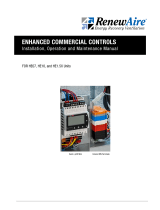
FIGURE 1.5.0 CHART OF AVAILABLE TURNDOWN OPTIONS BY FURNACE MODEL
AIRFLOW
Flue Gas
Exhaust
W
L
Combustion
Inlet
H
Model: GH-RTWO250
Drawing Type: Unit Dimension
Version: OCT23
AIRFLOW
Combustion Inlet
Flue Gas
Exhaust
W
L
H
Model: GH-INSI200
Drawing Type: Unit Dimension
Version: OCT23
AIRFLOW
Flue Gas
Exhaust
Combustion Inlet
W
L
H
Model: GH-RTNO100
Drawing Type: Unit Dimension
Version: JUL23
AIRFLOW
Flue Gas
Exhaust
Combustion Inlet
W
L
H
Model: GH-INKI150
Drawing Type: Unit Dimension
Version: OCT23
OUTDOOR FRONT EXHAUST
MODEL RT-WO
INDOOR SEPARATE INLET EXHAUST
MODEL IN-SI
INDOOR TOP EXHAUST
MODEL IN-KI
OUTDOOR TOP EXHAUST
MODEL RT-NO
RenewAire
Furnace
Model
1-Stage
(ON/OFF)
Available?
2-Stage
(High/Low)
Available?
Modulating
(5:1 Turndown)
Available?
Modulating
(10:1 Turndown)
Available?
RenewAire
Furnace
Model
1-Stage
(ON/OFF)
Available?
2-Stage
(High/Low)
Available?
Modulating
(5:1 Turndown)
Available?
Modulating
(10:1 Turndown)
Available?
GH-050 GH-200
IN-S YES YES YES NO IN-S YES YES YES YES
IN-K YES YES YES NO IN-K YES YES YES YES
RT-WO YES YES YES NO RT-WO YES YES YES YES
RT-NO YES YES YES NO RT-NO YES YES YES YES
GH-075 GH-250
IN-S YES YES YES NO IN-S YES YES YES YES
IN-K YES YES YES NO IN-K YES YES YES YES
RT-WO YES YES YES NO RT-WO YES YES YES YES
RT-NO YES YES YES NO RT-NO YES YES YES YES
GH-100 GH-300
IN-S YES YES YES NO IN-S YES YES YES YES
IN-K YES YES YES NO IN-K YES YES YES YES
RT-WO YES YES YES NO RT-WO YES YES YES YES
RT-NO YES YES YES NO RT-NO YES YES YES YES
GH-125 GH-350
IN-S YES YES YES NO IN-S YES YES YES YES
IN-K YES YES YES NO IN-K YES YES YES YES
RT-WO YES YES YES NO RT-WO YES YES YES YES
RT-NO YES YES YES NO RT-NO YES YES YES YES
GH-150 GH-400
IN-S YES YES YES NO IN-S YES YES YES YES
IN-K YES YES YES NO IN-K YES YES YES YES
RT-WO YES YES YES NO RT-WO YES YES YES YES
RT-NO YES YES YES NO RT-NO YES YES YES YES
GH-175
IN-S YES YES YES NO
IN-K YES YES YES NO
RT-WO YES YES YES NO
RT-NO YES YES YES NO

131.800.627.4499
GH-Series Indirect Gas-Fired Duct Furnace ACCESSORY
OVERVIEW
FIGURE 1.5.1 TYPICAL INSTALLATION OF INDOOR SEPARATE INLET
EXHAUST FURNACE
FIGURE 1.5.2 TYPICAL INSTALLATION OF INDOOR TOP EXHAUST FURNACE
FIGURE 1.5.3 TYPICAL INSTALLATION OF OUTDOOR TOP EXHAUST
FURNACE
FIGURE 1.5.4 TYPICAL PARALLEL FURNACE INSTALLATION
FIGURE 1.5.5 TYPICAL FACTORY-PROVIDED CONNECTION POINTS
HIGH- AND LOW-VOLTAGE
WIRING ENTRY FITTINGS
3/4” GAS CONNECTION
CONDENSATE DRAIN
TUBE
See figures below for examples of common installation approaches.

1.800.627.449914
GH-Series Indirect Gas-Fired Duct Furnace
ACCESSORY
1.6 SINGLE AND MULTIPLE FURNACE CONFIGURATIONS
1.7 USER INTERFACE
FIGURE 1.6.0 SINGLE UNIT—TOP VIEW
FIGURE 1.6.1 PARALLEL UNIT—TOP VIEW
4939 CFM [2331 l/s]
45˚F [7.2˚C] Entering
Air Temp
9978 CFM [4662 l/s]
45˚F [7.2˚C] Entering
Air Temp
300,000 Btuh [87,921 W]
Input
45˚F [25˚C] Rise
300,000 Btuh [87,921 W]
Input
45˚F [25˚C] Rise
300,000 Btuh [87,921 W]
Input
45˚F [25˚C] Rise
90˚F [32.2˚C]
Discharge
Air Temp
90˚F [32.2˚C]
Discharge
Air Temp
Pressure Drop .22" WC [54 Pa]
Pressure Drop .22" WC [54 Pa]
Based on equal airflow of
4939 cfm [2331 l/s] through each section
The User Interface (U/I) is the device that the owner uses to control operation of the furnace.
Single and two-stage furnaces can be ordered with a 2-stage duct thermostat and sensor.
Modulating furnaces can be ordered with an analog thermostat and sensor. The user interface
may be a simple ON/OFF switch, a thermostat or even a Building Management System (BMS).
Furnaces may be installed individually or in parallel. ALL FURNACES MUST BE INSTALLED ON
THE POSITIVE PRESSURE SIDE OF THE FAN. Refer to the previous page for typical examples
of common installation approaches. The maximum allowable discharge temperature is 160˚F
[71˚C] for any installation. Maximum design duct static pressure is 3.0 InWC [746.5 Pa]. The
examples below show recommended single and multiple furnace configurations.
Note that the examples below are based upon a specific Entering Air temperature. As Entering
Air temperatures vary, the resulting temperature rise will also vary.
EXAMPLE 1—SINGLE FURNACE
EXAMPLE 2—PARALLEL FURNACES
(KEEPS PRESSURE DROP (PD) LOW FOR LARGE CFM)
OVERVIEW

151.800.627.4499
GH-Series Indirect Gas-Fired Duct Furnace ACCESSORY
VENTING
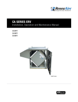
VERTICALLY VENTED DUCT FURNACES
Proper venting of the duct furnace is the responsibility of the installer. Vent piping is supplied by
others. When operated with the venting system in place, proper duct furnace operation must be
verified, including flue gas analysis of each connected furnace.
1. Use single wall or double wall (Type B) vent pipe of diameters shown below:
2. Maximize the height of the vertical run of vent pipe. A minimum of five (5) feet [1.5m] of
vertical pipe is required. The top of the vent pipe must extend at least two (2) feet [0.61m]
above the highest point on the roof. (Use Listed Type B vent for external runs).
3. An approved weatherproof vent cap must be installed to the vent termination.
4. Horizontal runs must not exceed 75% of the vertical height of the vent pipe, up to a maximum
of ten (10) feet [3m]. Horizontal runs should be pitched downward ¼" per foot [21mm/m] and
should be supported at 3 foot [1m] maximum intervals.
5. Design vent pipe runs to minimize the use of elbows. Each 90˚ elbow is equivalent to 5 feet
[1.5m] of straight vent pipe run.
6. Vent pipe should not be run through unheated spaces. If such runs cannot be avoided,
insulate vent pipe to prevent condensation inside vent pipe. Insulation should be a minimum
of ½" [12.7mm] thick, foil faced material suitable for temperatures up to 500˚F [260˚C]
7. Dampers must not be used in vent piping runs. Spillage of flue gases into the occupied space
could result.
8. Vent connectors serving Category 1 heaters must not be connected into any portion of a
mechanical draft system operating under positive pressure.
INPUT RATING (Btuh) INPUT RATING (W) VENT PIPE DIA.
50,000–199,999
200,000–400,000
14,653–58,614
58,615–117,228
5 in. [12.7cm]
6 in. [15.25cm]
2.0 VENTING
2.2 INDOOR FURNACE VENTING
All duct furnaces must be connected to a venting system to convey flue gases outside of the
building.
Vent systems must be sized and installed in accordance with ANSI Z223.1 (NFPA 54) or in
Canada CAN/CGA-B149. There are three acceptable methods for venting indoor furnace
installations:
u Vertical Indoor venting-uses building air for combustion, vent pipe run outdoors through
single roof penetration.
u Horizontal Indoor venting-uses building air for combustion, vent pipe run outdoors through
single wall penetration
u Separate Combustion 2-Pipe venting-uses outside air for combustion, vents outdoors–two
roof or wall penetrations.
2.1 EQUIVALENT LENGTH
Vent pipe lengths are given as “equivalent lengths”. When vent pipes are installed, they often
require that an elbow(s) be installed as part of the vent pipe. Elbows restrict free flow of gases
through the vent pipe. A 90˚ elbow added to a straight run of vent pipe is the equivalent of
adding 5 feet [1.5m] of length to the vent and adding a 45˚ elbow is the equivalent of adding 2.5
feet [0.75m] in length.
Example: A horizontal vent is 6.5 feet [2m] long, but it has a 45 degree elbow in the middle. Its
equivalent length is therefore 9 feet [2.75m] (6.5' + 2.5') [2.0m + 0.75m]. If this horizontal run
of venting were being used in conjunction with a vertical run of venting, the minimum length of
the vertical run must be 12 feet [3.66m] (horizontal equivalent length < 75% of vertical length).
NOTE: For assis-
tance with vent
sizing and design,
contact a reputable
company such as Precision
Vent or Tjernlund.

1.800.627.449916
GH-Series Indirect Gas-Fired Duct Furnace
ACCESSORY
VENTING
10 ft. (3.05m) Max.
(Not to exceed 75%
Vertical Flue Height)
5 ft Min.
(1.52m)
2 ft Min.
(0.61m)
Pitch pipe down 1/4in. (6mm)
pitch per 1 ft. (305mm)
horizontal run to allow for
condensate drainage
Roof Deck
Listed Vertical
Vent Terminal(s)
Condensate
Drain
Use insulated
Vent Outdoors
RenewAire LLC
SCALE:1:30
SIZE
DWG. NO.
A
MATERIAL:
FINISH:
SEE BILL OF MATERIAL
DO NOT SCALE DRAWING.
REMOVE ALL BURRS, BREAK
SHARP EDGES.
APPLICABLE STANDARDS: DIM.
AND TOL. ANSI Y14.5
UNLESS OTHERWISE SPECIFIED,
DIMENSIONS ARE IN INCHES.
TOLERANCES:
LINEAR
0.015
HOLE SIZE
0.005
ANGULARITY
3
SURFACE FINISH =
63 MICROINCH MINIMUM
DATE:
DRAWN BY:
CAH
1/20/17
Indoor Vertical Venting
SEPT17
SHEET 1 OF 1
4510 Helgesen Dr.
Madison, WI 53718 USA
TEL: (608) 221-4499
FAX: (608) 221-2824
TOLL FREE: (800) 627-4499
TITLE:
CHECKED BY:
DATE:
-- --
INDOOR VERTICAL VENTING
LEVEL
DESCRIPTION OF REVISION
DATE
BY
-
9/14/17
CAH
REMOVED THIMBLE
-
SEE BILL OF MATERIAL
FIGURE 2.2.0 INDOOR VERTICAL VENTING
NOTE: All installa-
tions must comply
with SMACNA
guidlines.
NOTE: All ductwork
and venting as
shown in illustra-
tions is supplied by
others and field installed.
NOTE: For assis-
tance with vent
sizing and design,
contact a reputable
company such as Precision
Vent or Tjernlund.
HORIZONTALLY VENTED DUCT FURNACES
Pressures in Category III venting systems are positive and therefore care must be taken to avoid
flue products from entering the heated space. Use only vent materials and components that are
UL listed and approved for Category III venting systems.
All vent pipe joints must be sealed to prevent leakage into the heated space. Follow instruction
provided with approved venting materials used. The proper vent pipe diameter must be used, to
insure proper venting of combustion products.
The total equivalent length of vent pipe must not exceed 50 ft. [15.25m]. Equivalent length is
the total length of straight sections, plus 5 ft. [1.52m] for each 90˚ elbow and 2.5 ft [0.76m] for
each 45˚ elbow.
The vent system must also be installed to prevent collection of condensate. Pitch horizontal
pipe runs downward ¼ in. per foot [21mm/m] toward the outlet to permit condensate drainage.
Insulate vent pipe exposed to cold air or routed through unheated areas. Insulate vent pipe
runs longer than 10 ft. [3m]. Insulation should be a minimum of ½ in. [12mm] thick foil faced
material suitable for temperatures up to 500˚F [260˚C]. Maintain 6 in. [152mm] clearance
between vent pipe and combustible materials.
A vent cap listed for horizontal venting must be provided. Vent cap inlet diameter must be same
as the required vent pipe diameter. The vent terminal must be at least 12 in. [305mm] from the
exterior wall that it passes through to prevent degradation of building material by flue gases.
The vent terminal must be located at least 1 ft. [305mm] above grade, or in snow areas, at least
3 ft. [1m] above snow line to prevent blockage. Additionally, the vent terminal must be installed
with a minimum horizontal clearance of 4 ft. [1.2m] from electric meters, gas meters, regulators
or relief equipment.
NOTE: A field-sup-
plied and installed
power vent may be
required for vent
runs longer than 50 equiv-
alent feet [15.25M].

171.800.627.4499
GH-Series Indirect Gas-Fired Duct Furnace ACCESSORY
VENTING
EACH DUCT FURNACE MUST HAVE ITS OWN INDIVIDUAL VENT PIPE AND TERMINAL. Do not
connect vent system from horizontally vented units to other vent systems or a chimney.
Through the wall vents shall not terminate over public walkways, or over an area where
condensate or vapor could create a nuisance or hazard.
TWO-PIPE SEPARATE COMBUSTION SYSTEMS
The furnace must be mounted with the burner section in a reasonably airtight vestibule
compartment, as these systems provide combustion air from outside the heated space and vent
the products of combustion outdoors. Additionally the heating unit must include the following:
1. A tooled door latch to ensure that door or panel is closed or in place during operation.
2. Approved vent terminals on both the supply air inlet and flue gas exhaust. NOTE: The inlet
and outlet terminals must be located in the same pressure zone to provide for safe appliance
operation.
3. For combustion air piping, use 24 gauge galvanized steel single wall pipe. Tape joints with
aluminum foil tape and secure with corrosion resistant screws.
4. Inlet air pipe must be same size as exhaust vent pipe based on input ratings.
5. For exhaust venting, use 24 gauge galvanized single wall or Type B vent for vertically vented
furnaces.
6. For exhaust venting, use only vent materials and components that are UL listed and approved
for Category III vent systems when venting horizontally.
7. Exhaust and vent piping must not exceed a combined 50 equivalent feet [15.25m].
Proper installation of air inlet and flue gas exhaust piping are essential to proper operation of
the duct furnace.
Separate combustion systems may not be common vented. Each furnace must have its own
individual air supply and flue gas exhaust vent.
FIGURE 2.2.1 INDOOR HORIZONTAL VENTING
1.0 ft
(0.3m)
Min.
2 ft.
(0.6m)
Min.
18 in.
(0.45m)
Min. at CL
5 ft. (1.52m) Min.
25 ft (7.6m)
Max. Equiv. Length
3 ft. (0.9m)
Above grade
or expected
snow depth
Pitch pipes down 1/4in.
(6mm) pitch per 1 ft. (305mm)
horizontal run to allow for
condensate drainage
Exterior Wall
Listed Horizontal
Vent Terminal(s)
Exhaust Vent
Combustion Air
Inlet
RenewAire LLC
SCALE:1:30
SIZE
DWG. NO.
A
MATERIAL:
FINISH:
SEE BILL OF MATERIAL
DO NOT SCALE DRAWING.
REMOVE ALL BURRS, BREAK
SHARP EDGES.
APPLICABLE STANDARDS: DIM.
AND TOL. ANSI Y14.5
UNLESS OTHERWISE SPECIFIED,
DIMENSIONS ARE IN INCHES.
TOLERANCES:
LINEAR
0.015
HOLE SIZE
0.005
ANGULARITY
3
SURFACE FINISH =
63 MICROINCH MINIMUM
DATE:
DRAWN BY:
CAH
1/20/17
Indoor Separated
Horizontal Venting
SHEET 1 OF 1
4510 Helgesen Dr.
Madison, WI 53718 USA
TEL: (608) 221-4499
FAX: (608) 221-2824
TOLL FREE: (800) 627-4499
TITLE:
CHECKED BY:
DATE:
-- --
INDOOR SEPARATED HORIZONTAL VENTING
LEVEL
DESCRIPTION OF REVISION
DATE
BY
A
--
RELEASE FOR PROTOTYPE
-
SEE BILL OF MATERIAL
NOTE: For assis-
tance with vent
sizing and design,
contact a reputable
company such as Precision
Vent or Tjernlund.
NOTE: All installa-
tions must comply
with SMACNA
guidelines.
NOTE: All ductwork
and venting as
shown in illustra-
tions is supplied by
others and field installed.

1.800.627.449918
GH-Series Indirect Gas-Fired Duct Furnace
ACCESSORY
REVISED
-
RenewAire LLC
SCALE:1:30 SIZE
DWG. NO.
A
MATERIAL:
FINISH:
-
3-21-17
-
BY SHEET 1 OF 1
Indoor Separated
3
DATE:
SEE BILL OF MATERIAL
DATE
CHECKED BY:
DESCRIPTION OF REVISION
LEVEL
TITLE: INDOOR SEPARATED VERTICAL VENTING
TOLL FREE: (800) 627-4499
--
--
REMOVE ALL BURRS, BREAK
63 MICROINCH MINIMUM
DATE:
DRAWN BY:
CAH
DO NOT SCALE DRAWING.
SURFACE FINISH =
Vertical Venting
1/20/17
AND TOL. ANSI Y14.5
SHARP EDGES.
APPLICABLE STANDARDS: DIM.
UNLESS OTHERWISE SPECIFIED,
DIMENSIONS ARE IN INCHES.
TOLERANCES:
LINEAR 0.015
HOLE SIZE 0.005
ANGULARITY
4510 Helgesen Dr.
Madison, WI 53718 USA
TEL: (608) 221-4499
FAX: (608) 221-2824
SEE BILL OF MATERIAL
Roof Deck
Vent Terminal(s)
Listed Vertical
(Both Pipes)
Exhaust Vent
Cleanout Cap
Tee Fitting with
Drip Leg and
Combustion Air
Inlet
Min.
(0.75m)
expected snow depth.
Min.
(0.3m)
clearance (height) to exceed
2.5 ft
18 in.
Note: Provide sufficient
Min.
18 in.
(0.46m)
6 ft.
(1.8m)
Min.
To Wall or
Adjoining Building
FIGURE 2.2.2 VERTICAL VENTING—SEPARATE COMBUSTION
1.0 ft
(0.3m)
Min.
2 ft.
(0.6m)
Min.
18 in.
(0.45m)
Min. at CL
5 ft. (1.52m) Min.
25 ft (7.6m)
Max. Equiv. Length
3 ft. (0.9m)
Above grade
or expected
snow depth
Pitch pipes down 1/4in.
(6mm) pitch per 1 ft. (305mm)
horizontal run to allow for
condensate drainage
Exterior Wall
Listed Horizontal
Vent Terminal(s)
Exhaust Vent
Combustion Air
Inlet
RenewAire LLC
SCALE:1:30
SIZE
DWG. NO.
A
MATERIAL:
FINISH:
SEE BILL OF MATERIAL
DO NOT SCALE DRAWING.
REMOVE ALL BURRS, BREAK
SHARP EDGES.
APPLICABLE STANDARDS: DIM.
AND TOL. ANSI Y14.5
UNLESS OTHERWISE SPECIFIED,
DIMENSIONS ARE IN INCHES.
TOLERANCES:
LINEAR
0.015
HOLE SIZE
0.005
ANGULARITY
3
SURFACE FINISH =
63 MICROINCH MINIMUM
DATE:
DRAWN BY:
CAH
1/20/17
Indoor Separated
Horizontal Venting
SHEET 1 OF 1
4510 Helgesen Dr.
Madison, WI 53718 USA
TEL: (608) 221-4499
FAX: (608) 221-2824
TOLL FREE: (800) 627-4499
TITLE:
CHECKED BY:
DATE:
-- --
INDOOR SEPARATED HORIZONTAL VENTING
LEVEL
DESCRIPTION OF REVISION
DATE
BY
A
--
RELEASE FOR PROTOTYPE
-
SEE BILL OF MATERIAL
FIGURE 2.2.3 HORIZONTAL VENTING—SEPARATE COMBUSTION
NOTE: BE SURE THE VENT CAP USED FOR HORIZONTAL VENTING APPLICATIONS IS APPROVED
FOR HORIZONTAL APPLICATION. CERTAIN MANUFACTURERS’ VENT TERMINALS ARE
APPROVED FOR VERTICAL INSTALLATION ONLY.
VENTING
NOTE: For assis-
tance with vent
sizing and design,
contact a reputable
company such as Precision
Vent or Tjernlund.
NOTE: All installa-
tions must comply
with SMACNA
guidelines.
NOTE: All ductwork
and venting as
shown in illustra-
tions is supplied by
others and field installed.

191.800.627.4499
GH-Series Indirect Gas-Fired Duct Furnace ACCESSORY
2.3 OUTDOOR FURNACE VENTING
Outdoor furnaces must be individually vented.
The venting system is designed for direct discharge of flue gases to the outdoors. The vent
discharge opening should be located to provide an unobstructed discharge to the outside and
should be located as far from the combustion air as possible, but in the same pressure zone.
Vent duct should pitch down toward outlet, to ensure that any condensate that occurs in the
vent duct drains away from the combustion blower fan housing. The duct opening should be
protected by a 1/2" x 1/2" screen. A fan hood is used over the discharge opening to prevent
wind-driven rain from entering the vent duct, but should not intersect the flue gas discharge
path.
Where sufficient clearance for proper horizontal venting cannot be provided, or in jurisdictions
requiring a 4 foot [1.2m] separation between the flue gas discharge and combustion air inlet,
flue gases should be vented vertically. Refer to illustration below for suitable venting method. A
vent adapter is required to transition from the rectangular ID fan discharge to round vent pipe.
Joints in the vestibule must be sealed.
Vent pipe must terminate at least 1 foot [0.3m] above the cabinet. The vent must be located on
the same side of the furnace as the combustion air opening. Condensation in the vent pipe is
likely during furnace start-up cycle and provision for drainage must be provided in closed vent
piping.
REVISED
-
RenewAire LLC
SCALE:1:24 SIZE
DWG. NO.
A
MATERIAL:
FINISH:
-
3-21-17
-
BY SHEET 1 OF 1
SURFACE FINISH =
3
DATE:
SEE BILL OF MATERIAL
DATE
CHECKED BY:
DESCRIPTION OF REVISION
LEVEL
TITLE: OUTDOOR HORIZONTAL VENTING
TOLL FREE: (800) 627-4499
--
--
REMOVE ALL BURRS, BREAK
63 MICROINCH MINIMUM
DATE:
DRAWN BY:
CAH 2/1/17 Outdoor Horizontal Venting
DO NOT SCALE DRAWING.
AND TOL. ANSI Y14.5
SHARP EDGES.
APPLICABLE STANDARDS: DIM.
UNLESS OTHERWISE SPECIFIED,
DIMENSIONS ARE IN INCHES.
TOLERANCES:
LINEAR 0.015
HOLE SIZE 0.005
ANGULARITY
4510 Helgesen Dr.
Madison, WI 53718 USA
TEL: (608) 221-4499
FAX: (608) 221-2824
SEE BILL OF MATERIAL
Combustion Air Opening
Equipment Pad
Roof Deck orCombustion Air Exhaust
FIGURE 2.3.0 OUTDOOR HORIZONTAL VENTING
FIGURE 2.3.1 OUTDOOR VERTICAL VENTING
REVISED
-
RenewAire LLC
SCALE:1:24 SIZE
DWG. NO.
A
MATERIAL:
FINISH:
-
3-21-17
-
BY SHEET 1 OF 1
SURFACE FINISH =
3
DATE:
SEE BILL OF MATERIAL
DATE
CHECKED BY:
DESCRIPTION OF REVISION
LEVEL
TITLE:
OUTDOOR VERTICAL VENTING
TOLL FREE: (800) 627-4499
--
--
REMOVE ALL BURRS, BREAK
63 MICROINCH MINIMUM
DATE:
DRAWN BY:
CAH 2/1/17 Outdoor Vertical Venting
DO NOT SCALE DRAWING.
AND TOL. ANSI Y14.5
SHARP EDGES.
APPLICABLE STANDARDS: DIM.
UNLESS OTHERWISE SPECIFIED,
DIMENSIONS ARE IN INCHES.
TOLERANCES:
LINEAR 0.015
HOLE SIZE 0.005
ANGULARITY
4510 Helgesen Dr.
Madison, WI 53718 USA
TEL: (608) 221-4499
FAX: (608) 221-2824
SEE BILL OF MATERIAL
Combustion Air Opening
Equipment Pad
Roof Deck or
Listed Vent Terminal
12 in. Min.
48 in. Min.
required in some
jurisdictions
VENTING
18 in Min.

1.800.627.449920
GH-Series Indirect Gas-Fired Duct Furnace
ACCESSORY
3.0 GAS SUPPLY
Installation of piping must conform with local building codes and ordinances, or, in the absence
of local codes, with ANSI Z223.1, the National Fuel Gas Code. In Canada, installation must be in
accordance with CAN/CGA-B149 for natural gas and B149.2 for propane units.
Gas piping must be sized for the total BTU input of all furnaces serviced by a single supply.
Be sure that gas regulators servicing more than one furnace have the proper pipe and internal
orifice size for the total input of all furnaces serviced by the regulator.
See table below for minimum inlet gas pressure required and maximum permissible supply
pressure at each furnace.
Natural Gas Propane Gas
Minimum (50 to 400 MBH models): 5.0 InWC 11.0 InWC
[14,653 to 117,228 W] [1244 Pa] [2737 Pa]
Maximum Inlet Pressure: 13.5 InWC 13.5 InWC
[3359 Pa] [3359 Pa]
Connect a fitting suitable for connection to a pressure gauge capable of measuring gas
pressure to 1/8” NPT tap provided on the inlet side of the gas valve or manual shut-off tapping.
Measure inlet pressure to each furnace serviced by a single regulator with all furnaces in
operation.
Gas supply piping to multiple furnaces should be con Figured to provide equal pressure to all
furnaces. With all furnaces operating at full output, minimum supply gas pressure should be
checked at all furnaces.
A drip leg (sediment trap) and a manual shut off valve must be provided immediately upstream
of the gas control on the heating unit. To facilitate servicing of the unit, installation of a union is
recommended.
All gas supply and furnace connections must be leak tested prior to placing equipment in
service.
FIGURE 3.0.0 EXAMPLE OF MULTIPLE FURNACE SUPPLY GAS PIPING
GAS SUPPLY
Page is loading ...
Page is loading ...
Page is loading ...
Page is loading ...
Page is loading ...
Page is loading ...
Page is loading ...
Page is loading ...
Page is loading ...
Page is loading ...
Page is loading ...
Page is loading ...
Page is loading ...
Page is loading ...
Page is loading ...
Page is loading ...
Page is loading ...
Page is loading ...
Page is loading ...
Page is loading ...
Page is loading ...
Page is loading ...
Page is loading ...
Page is loading ...
Page is loading ...
Page is loading ...
Page is loading ...
Page is loading ...
Page is loading ...
Page is loading ...
Page is loading ...
Page is loading ...
-
 1
1
-
 2
2
-
 3
3
-
 4
4
-
 5
5
-
 6
6
-
 7
7
-
 8
8
-
 9
9
-
 10
10
-
 11
11
-
 12
12
-
 13
13
-
 14
14
-
 15
15
-
 16
16
-
 17
17
-
 18
18
-
 19
19
-
 20
20
-
 21
21
-
 22
22
-
 23
23
-
 24
24
-
 25
25
-
 26
26
-
 27
27
-
 28
28
-
 29
29
-
 30
30
-
 31
31
-
 32
32
-
 33
33
-
 34
34
-
 35
35
-
 36
36
-
 37
37
-
 38
38
-
 39
39
-
 40
40
-
 41
41
-
 42
42
-
 43
43
-
 44
44
-
 45
45
-
 46
46
-
 47
47
-
 48
48
-
 49
49
-
 50
50
-
 51
51
-
 52
52


Ask a question and I''ll find the answer in the document
Finding information in a document is now easier with AI
Related papers
-
 RenewAire CA2XIN Owner's manual
-
 RenewAire Filter Alarm Owner's manual
-
 RenewAire EV Premium Owner's manual
-
 RenewAire Curb Clip Owner's manual
-
 RenewAire Curb Clip Owner's manual
-
 RenewAire Enhanced Controls Owner's manual
-
 RenewAire CA4XRT Owner's manual
-
 RenewAire Premium Controls Owner's manual
-
 RenewAire EV Premium Airflow Operating instructions
-
 RenewAire RD4XRT Owner's manual


Other documents
-
Greenheck 474645 PVF/PVG Indirect Gas-Fired Heat Modules pre-August 2015 Operating instructions
-
Unitary products group G8C Installation guide
-
-
Coleman UGAE075BUB Installation guide
-
York GY8S-E Installation guide
-
-
AAON V3-B Installation, Operation & Maintenance Instructions Manual
-
-
Trane Gas Unit Heaters Installation and Maintenance Manual
-