Gefen GTB-DPKVM-3CAT7 User manual
- Category
- Console extenders
- Type
- User manual
This manual is also suitable for

Audio
Embedder
3GSDI
Release A7
User Manual
GTB-DPKVM-3CAT7
GTB-DPKVM-3CAT7-BLK
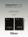
DisplayPort KVM
Extender over CAT-7

DisplayPort KVM Extender over CAT-7
Important Safety Instructions
ii
GENERAL SAFETY INFORMATION
1. Read these instructions.
2. Keep these instructions.
3. Heed all warnings.
4. Follow all instructions.
5. Do not use this product near water.
6. Clean only with a dry cloth.
7. Do not block any ventilation openings. Install in accordance with the manufacturer’s
instructions.
8. Do not install or place this product near any heat sources such as radiators, heat
registers, stoves, or other apparatus (including ampliers) that produce heat.
9. Do not defeat the safety purpose of the polarized or grounding-type plug. A polarized
plug has two blades with one wider than the other. A grounding type plug has two
blades and a third grounding prong. The wide blade or the third prong are provided for
your safety. If the provided plug does not t into your outlet, consult an electrician for
replacement of the obsolete outlet.
10. Protect the power cord from being walked on or pinched particularly at plugs,
convenience receptacles, and the point where they exit from the apparatus.
11. Only use attachments/accessories specied by the manufacturer.
12. To reduce the risk of electric shock and/or damage to this product, never handle or
touch this unit or power cord if your hands are wet or damp. Do not expose this
product to rain or moisture.
13. Unplug this apparatus during lightning storms or when unused for long periods of time.
14. Refer all servicing to qualied service personnel. Servicing is required when the
apparatus has been damaged in any way, such as power-supply cord or plug is
damaged, liquid has been spilled or objects have fallen into the apparatus,
the apparatus has been exposed to rain or moisture, does not operate normally,
or has been dropped.
15. Batteries that may be included with this product and/or accessories should never be
exposed to open ame or excessive heat. Always dispose of used batteries
according to the instructions.

DisplayPort KVM Extender over CAT-7
Warranty Information
Gefen warrants the equipment it manufactures to be free from defects in material and
workmanship.
If equipment fails because of such defects and Gefen is notied within two (2) years from
the date of shipment, Gefen will, at its option, repair or replace the equipment, provided
that the equipment has not been subjected to mechanical, electrical, or other abuse or
modications. Equipment that fails under conditions other than those covered will be
repaired at the current price of parts and labor in effect at the time of repair. Such repairs
are warranted for ninety (90) days from the day of reshipment to the Buyer.
This warranty is in lieu of all other warranties expressed or implied, including without
limitation, any implied warranty or merchantability or tness for any particular purpose, all of
which are expressly disclaimed.
1. Proof of sale may be required in order to claim warranty.
2. Customers outside the US are responsible for shipping charges to and from Gefen.
3. Copper cables are limited to a 30 day warranty and cables must be in their original
condition.
The information in this manual has been carefully checked and is believed to be accurate.
However, Gefen assumes no responsibility for any inaccuracies that may be contained
in this manual. In no event will Gefen be liable for direct, indirect, special, incidental, or
consequential damages resulting from any defect or omission in this manual, even if
advised of the possibility of such damages. The technical information contained herein
regarding the features and specications is subject to change without notice.
For the latest warranty coverage information, refer to the Warranty and Return Policy under
the Support section of the Gefen Web site at www.gefen.com.
PRODUCT REGISTRATION
Please register your product online by visiting the Register Product page under the
Support section of the Gefen Web site.
iii

iv
DisplayPort KVM Extender over CAT-7
Gefen, LLC
c/o Customer Service
20600 Nordhoff St.
Chatsworth, CA 91311
Telephone: (818) 772-9100
(800) 545-6900
Fax: (818) 772-9120
Visit us on the Web: www.gefentoolbox.com
Technical Support Hours: 8:00 AM to 5:00 PM Monday - Friday, Pacic Time
DisplayPort KVM Extender over CAT-7 is a trademark of Gefen, LLC.
Important Notice
Gefen, LLC reserves the right to make changes in the hardware, packaging, and any
accompanying documentation without prior written notice.
© 2013 Gefen, LLC. All Rights Reserved.
All trademarks are the property of their respective owners.
Contacting Gefen Technical Support

v
• CAT-7 cables should not exceed 100 feet (30 meters).
• Resolutions up to 1920 x 1200 (WUXGA) or 1080p Full HD plus USB are supported
when using two CAT-7 cables. Three CAT-7 cables must be used to support
2560 x 1600 (WQXGA) plus USB. See Connecting the DisplayPort KVM Extender
over CAT-7 for details.
• The DisplayPort KVM Extender over CAT-7 only supports 8-bit color.
• This product extends DisplayPort video only. It does not support audio.
Operating Notes
DisplayPort KVM Extender over CAT-7

vi
Features
• Extends DisplayPort and USB up to 100 feet (30 meters)
• Supports resolutions up to 2560 x 1600 and USB over three CAT-7 cables,
and up to 1920 x 1200 or 1080p Full HD at 120Hz and USB over two CAT-7 cables
• HDCP compliant
• Supports DisplayPort 1.1a
• Supports USB 2.0 at 480 Mbps
• Backward-compatible with USB 1.1
• 16-position EQ rotary switch to compensate for cable skew
• HPD Auto-Calibration button
• Pre-emphasis switch
• Drive level switch
• Boost level switches
• Power On indicator
• Independent Video and USB Link indicators
• Locking power supplies
• Surface-mountable
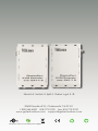
• Available in Black and White
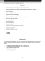
Packing List
The DisplayPort KVM Extender over CAT-7 ships with the items listed below. If any of these
items are not present in the box when you rst open it, immediately contact your dealer or
Gefen.
• 1 x DisplayPort KVM Extender over CAT-7 (Sender unit)
• 1 x DisplayPort KVM Extender over CAT-7 (Receiver unit)
• 1 x 6 ft. DisplayPort cable (M-M)
• 1 x 6 ft. USB cable (A-B)
• 2 x 5V DC power supplies
• 1 x Quick-Start Guide
DisplayPort KVM Extender over CAT-7
Features and Packing List
1080P

vii
3GSDI Audio Embedder
DisplayPort KVM Extender over CAT-7
Table of Contents
vii
01 Getting Started
Panel Layout ......................................................................................................... 2
Sender Unit (Front) ....................................................................................... 2
Sender Unit (Back) ........................................................................................ 3
Receiver Unit (Front) ..................................................................................... 4
Receiver Unit (Back) ..................................................................................... 5
Installation ............................................................................................................. 6
Connecting the DisplayPort KVM Extender over CAT-7 ............................... 6
Sample Wiring Diagram ................................................................................ 7
02 Operating the DisplayPort KVM Extender
over CAT-7
LED Indicators ..................................................................................................... 10
Sender Unit ................................................................................................. 10
Receiver Unit ............................................................................................... 11
DIP Switch Conguration .................................................................................... 12
Hot-Plug Detect (HPD) ........................................................................................ 13
Adjusting the Signal Quality ................................................................................ 14
03 Appendix
Cable Termination ............................................................................................... 18
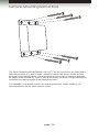
Surface-Mounting Instructions............................................................................. 19
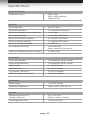
Specications ...................................................................................................... 20


DisplayPort KVM
Extender over CAT-7
01 Getting Started
Panel Layout ......................................................................................................... 2
Sender Unit (Front) ....................................................................................... 2
Sender Unit (Back) ........................................................................................ 3
Receiver Unit (Front) ..................................................................................... 4
Receiver Unit (Back) ..................................................................................... 5
Installation ............................................................................................................. 6
Connecting the DisplayPort KVM Extender over CAT-7 ............................... 6
Sample Wiring Diagram ................................................................................ 7

page | 2
Sender Unit (Front)
ID Name Description
1 USB Link Connect a CAT-7 cable between this jack
and the USB Link jack on the Receiver
unit. This RJ-45 jack must be used when
extending USB.
2 Link 1 Connect a CAT-7 cable between this RJ-45
jack and the Link 1 jack on the Receiver unit.
3 Link 2 Connect a CAT-7 cable between this
RJ-45 jack and the Link 2 jack on the
Receiver unit. Both Link 1 and Link 2 jacks
(two CAT-7 cables) must be used when
extending video resolutions up to
2560 x 1600.
Getting Started
Panel Layout
1
2 3

page | 3
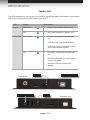
Sender Unit (Back)
ID Name Description
1 5V DC Connect the included 5V DC locking power
supply to this connector and plug the AC
power cord into an available electrical outlet.
Only use the power supply shipped with this
unit.
2 DP In Connect a Hi-Def source to this port using a
DisplayPort cable.
3 Power This LED indicator will glow bright blue when
the unit is powered.
4 Host This LED will glow bright green when the
host USB device is connected to the USB
In port.
5 USB In Connect the included USB cable between
this port and a computer (or other USB
host device).
Getting Started
Panel Layout
4
51 2 3

page | 4
Getting Started
Panel Layout
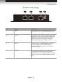
Receiver Unit (Front)
ID Name Description
1 Link 1 Connect a CAT-7 cable between this RJ-45
jack and the Link 1 jack on the Sender unit.
2 Link 2 Connect a CAT-7 cable between this RJ-45
jack and the Link 2 jack on the Sender unit.
Both Link 1 and Link 2 jacks (two CAT-7
cables) must be used when extending
video resolutions up to 2560 x 1600.
3 Link 2 Connect a CAT-7 cable between this jack
and the USB Link jack on the Sender
unit. This RJ-45 jack must be used when
extending USB.
4 5V DC Connect the included 5V DC locking power
supply to this connector and plug the AC
power cord into an available electrical outlet.
Only use the power supply shipped with this
unit.
1 2 3 4

page | 5
Getting Started
Panel Layout
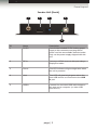
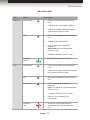
Receiver Unit (Back)
ID Name Description
1 Host This LED will glow bright green when the
host USB device is connected to the USB
In port.
2 USB Out Connect up to two USB devices (mouse,
keyboard, camera, etc.) to these ports.
3 Link This LED indicator will glow bright green
when a CAT-7 cable is connected between
the USB Link ports on both the Sender and
Receiver unit.
4 DP Out Connect a DisplayPort cable from this port
to the display.
5 HPD Press this button to cycle the HPD line on
the Receiver unit. See Hot-Plug Detect
(HPD) for details.
6 EQ Use this EQ rotary switch to adjust the
quality of the output signal, based on
the length and type of CAT-7 cable that
is being used. See Adjusting the Signal
Quality for more information.
1 2 3 4 5 6

Page Title
page | 6
Getting Started
Installation
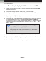
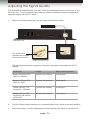
Connecting the DisplayPort KVM Extender over CAT-7
1. Use the included DisplayPort cable to connect the DisplayPort source to the DP In
port on the Sender unit.
2. Connect the Receiver unit to the display using a DisplayPort cable.
3. Use the included USB cable to connect the USB host device to the USB In port
on the Sender unit.
4. Connect up to two USB devices (keyboard, mouse, external drive, etc) to the
USB Out ports on the Receiver unit.
5. Connect two CAT-7 cables between the Sender and Receiver units. Each connector
on the Sender and Receiver unit is identied as Link 1, Link 2, and USB Link.
When connecting the CAT-7 cables, make sure that each CAT-7 cable on the Sender
unit is connected to the corresponding jacks on Receiver unit (e.g. Link 1 → Link 1,
Link 2 → Link 2).
6. Connect a CAT-7 cable between the USB Link jack on the Sender and Receiver unit.
7. Connect the included 5V DC locking power supplies to the Sender and Receiver unit.
Do not overtighten the locking connectors.
8. Connect the AC power cords from each power supply to available electrical outlets.
NOTE: The DisplayPort KVM Extender over CAT-7 will support
resolutions up to 1920 x 1200 (WUXGA) and 1080p Full HD if a
single CAT-7 cable is used. Two CAT-7 cables must be used to
support resolutions up to 2560 x 1600.
If only a single CAT-7 cable will be used, the CAT-7 cable must be
connected between the Link 1 connectors on both the Sender and
Receiver unit.

page | 7
Getting Started
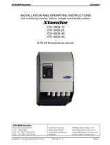
Sample Wiring Diagram
Installation
GTB-DPKVM-3CAT7
CAT-7 LINK CABLE
(Up to 100 ft)
DISPLAYPORT CABLE
Sender
Receiver
USB CABLE
DisplayPort Display
Computer
USB Mouse
USB Keyboard


DisplayPort KVM
Extender over CAT-7
02 Operating the
DisplayPort KVM Extender
over CAT-7
LED Indicators ..................................................................................................... 10
Sender Unit ................................................................................................. 10
Receiver Unit ............................................................................................... 11
DIP Switch Conguration .................................................................................... 12
Hot-Plug Detect (HPD) ........................................................................................ 13
Adjusting the Signal Quality ................................................................................ 14

page | 10
Sender Unit
The LED indicators on the Sender and Receiver unit provide basic information on the current
status of the DisplayPort KVM Extender over CAT-7.
LED Status Description
Power Solid blue • Power connected to Sender unit.
Off • No power supplied to Sender unit.
Host USB Solid green • Power connected to the Sender
unit.
• USB devices connected properly.
• USB link integrity between Sender
and Receiver unit is good.
Off • No power connected to the Sender
unit.
• No DisplayPort source connected or
source not active.
• Receiver unit not connected to
display.
Operating the DisplayPort KVM Extender over CAT-7
LED Indicators
Power Host USB Indicator
LinkUSB Link Indicator
Sender unit
Receiver unit

page | 11
Receiver Unit
LED Status Description
USB Link Solid green • Power connected to the Receiver
unit.
• USB devices connected properly.
• USB link integrity between Sender
and Receiver unit is good.
Off • No power supplied to the Receiver
unit.
• USB host not connected.
• CAT-7 cable not connected
between
USB Link jack on Sender and
Receiver unit.
• Possible defective CAT-7 cable.
Flashing
green
• USB devices not connected.
Link Solid green • Power connected to the Receiver
unit.
• Video link integrity between Sender
and Receiver unit is good.
Off • No power supplied to the Receiver
unit.
Solid red • CAT-7 cable not connected
between
Link 1 / Link 2 jack on Sender and
Receiver unit.
• Possible defective CAT-7 cable.
• Source / sink (display) not
connected.
Flashing
red
• Receiver unit is attempting to
establish a link with the Sender
unit.
Operating the DisplayPort KVM Extender over CAT-7
LED Indicators

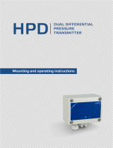
page | 12
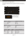
Operating the DisplayPort KVM Extender over CAT-7
The DisplayPort KVM xtender over CAT-7 contains four DIP switches on the bottom of
the Sender unit. Adjust the DIP switch settings based on the type and cable length that is
being used.
DIP Switch Position Differential Output Voltage
DIP 1 ON (default) 1.2 Vpp
CENTER 1.0 Vpp
OFF 600 mVpp
DIP Switch Position Pre-emphasis Select
DIP 2 ON (default) 9 dB
CENTER 6 dB
OFF 0 dB
DIP Switch Position
DIP 3
Position
DIP 4
Boost Level (dB) @ 5 GHz
DIP 3
DIP 4
OFF OFF 2.7 to 7.3 dB
OFF ON 12.2 to 16.6 dB
ON OFF 20.6 to 24.8 dB
ON ON 27.6 to 28.9
1 2 3 4
DIP Switch Conguration
DIP switches located on the
bottom of the Sender Unit.
If the DIP switch is ON, it
will be in the “up” position.
Sender unit
Page is loading ...
Page is loading ...
Page is loading ...
Page is loading ...
Page is loading ...
Page is loading ...
Page is loading ...
Page is loading ...
Page is loading ...
Page is loading ...
-
 1
1
-
 2
2
-
 3
3
-
 4
4
-
 5
5
-
 6
6
-
 7
7
-
 8
8
-
 9
9
-
 10
10
-
 11
11
-
 12
12
-
 13
13
-
 14
14
-
 15
15
-
 16
16
-
 17
17
-
 18
18
-
 19
19
-
 20
20
-
 21
21
-
 22
22
-
 23
23
-
 24
24
-
 25
25
-
 26
26
-
 27
27
-
 28
28
-
 29
29
-
 30
30


Gefen GTB-DPKVM-3CAT7 User manual
- Category
- Console extenders
- Type
- User manual
- This manual is also suitable for
Ask a question and I''ll find the answer in the document
Finding information in a document is now easier with AI
Related papers
-
Gefen EXT-DP-2CAT7 User manual
-
-
Gefen AUD-1000 User manual
-
-
-
Gefen EXT-USB-MINI2N User manual
-
-
Gefen GTB-USB2.0-4LR-BLK Owner's manual
-
Gefen GTB-3DTV-KVM User manual
-
Other documents
-
Comprehensive EXT-UHD-CAT5-ELRPOL User manual
-
Epson Bocs User manual
-
Cisco UC500 series Configuration manual
-
 Studer Innotec XTH 8000-48 User manual
-
 Aeca Xtender BTS-01 User manual
-
Motorola HPD 1000 User manual
-
 DESTACO CAMCO GTB Series User manual
-
Samlexpower XTH 3000-12 Owner's manual
-
STECA XTENDER User manual
-
 Sentera Controls HPD-G-1K0 Mounting Instruction


