IN USE/
CONDUCTOR
LINK/
ACTIVITY
tm
Obtaining Other Language Versions: To obtain information in another language about
the use of this product, please contact your local Crown Distributor. If you need assistance
locating your local distributor, please contact Crown at 574-294-8000.
This manual does not include all of the details of design, production, or variations of the
equipment. Nor does it cover every possible situation which may arise during installation,
operation or maintenance. If special assistance is needed beyond the scope of this manual,
please contact the Crown Technical Support Group.
The information provided in this manual was deemed accurate as of the publication date.
However, updates to this information may have occurred. To obtain the latest version of this
manual, please visit the Crown website at www.crownaudio.com.
Trademark Notice: Crown, Crown Audio, Amcron, Com-Tech, Macro-Tech, IQ and IQ
System are registered trademarks of Crown International. TCP/IQ, SmartAmp, IQ2, PIP and
PIP2 are trademarks of Crown International. HiQnet is a trademark of Harman International
Industries, Inc. Other trademarks are the property of their respective owners.
Some models may be exported under the name Amcron.
®
©2008 by Crown Audio
®
Inc., 1718 W. Mishawaka Rd., Elkhart, Indiana 46517-9439
U.S.A. Telephone: 574-294-8000
136763-6
4/08
Network
Programmable Input Processors with HiQnet™, TCP/IQ™,
SmartAmp™Features, Load Supervision for Crown PIP2™-Compatible
Amplifiers
, and CobraNet™
Connectivity (USP3/CN only)
Networked PIP Series Reference Manual
ANALOG AUDIO INPUTS
TCP / IQ
PIP-LITE
PIP-USP3
PIP-USP3/CN
136763-7_4-08_networked_pip-series_reference_manual.fm Page 1 Monday, March 17, 2008 11:17 AM

Networked PIP Series
page 2
Reference Manual
Crown Technical Support
1718 W. Mishawaka Rd., Elkhart, Indiana 46517-9439 U.S.A.
Phone: 800-342-6939 (North America, Puerto Rico and Virgin Islands) or 574-294-8200
Fax: 574-294-8301 Internet: http://www.crownaudio.com
FCC COMPLIANCE NOTICE
This device complies with part 15 of the FCC rules. Operation is subject to the following
two conditions: (1) This device may not cause harmful interference, and (2) this device
must accept any interference received, including interference that may cause undesired
operation.
CAUTION: Changes or modifications not expressly approved by the party responsible for
complicance could void the user’s authority to operate the euqipment.
NOTE: This equipment has been tested and found to comply with the limits for a Class B
digital device, pursuant to part 15 of the FCC Rules. These limits are designed to provide
reasonable protection against harmful interference in a residential installation. This
equipment generates, uses, and can radiate radio frequency energy and, if not installed
and used in accordance with the instruction manual, may cause harmful interference to
radio communications. However, there is no guarantee that interference will not occur in a
particular installation. If this equipment does cause harmful interference to radio or televi-
sion reception, which can be determined by turning the equipment off and on, the user is
encouraged to try to correct the interference by one or more of the following measures:
• Reorient or relocate the receiving antenna.
• Increase the separation between the equipment and receiver.
• Connect the equipment into an outlet on a circuit different from that to which the
receiver is connected.
• Consult the dealer or an experienced radio/TV technician for help.
WARNING
TO REDUCE THE RISK OF ELECTRIC
SHOCK, DO NOT EXPOSE THIS
EQUIPMENT TO RAIN OR MOISTURE!
WATCH FOR THESE SYMBOLS. The exclamation point triangle is
used to alert the user to important operating or maintenance
instructions.
The lightning bolt triangle is used to alert the user to the risk of
electric shock.
This product complies with CISPR22 Emissions standard,
EN55103-1 Emissions standard, and EN55103-2 Immunity standard.
136763-7_4-08_networked_pip-series_reference_manual.fm Page 2 Monday, March 17, 2008 11:17 AM

page 3
Reference Manual
Networked PIP Series
DECLARATION of CONFORMITY
Crown Audio, Inc.
1718 W. Mishawaka Rd.
Elkhart, IN 46517 U.S.A.
EMC Standards:
EN 55103-1:1995 Electromagnetic Compatibility – Product Family Standard for Audio, Video, Audio-
Visual and Entertainment Lighting Control Apparatus for Professional Use, Part 1: Emissions
EN 55103-1:1995 Magnetic Field Emissions-Annex A @ 10 cm and 1 M
EN 61000-3-3:1995 Limitation of Voltage Fluctuations and Flicker in Low-Voltage Supply Systems
Rated Current ≤16A
EN 55022:1992 + A1:1995 & A2:1997 Limits and Methods of Measurement of Radio Disturbance
Characteristics of ITE: Radiated, Class B Limits; Conducted, Class B
EN 55103-2:1996 Electromagnetic Compatibility – Product Family Standard for Audio, Video, Audio-
Visual and Entertainment Lighting Control Apparatus for Professional Use, Part 2: Immunity
EN 61000-4-2:1995 Electrostatic Discharge Immunity (Environment E2-Criteria B, 4k V Contact, 8k V
Air Discharge)
EN 61000-4-3:1996 Radiated, Radio-Frequency, Electromagnetic Immunity (Environment E2, criteria A)
EN 61000-4-4:1995 Electrical Fast Transient/Burst Immunity (Criteria B)
EN 61000-4-5:1995 Surge Immunity (Criteria B)
EN 61000-4-6:1996 Immunity to Conducted Disturbances Induced by Radio-Frequency Fields
(Criteria A)
EN 61000-4-11:1994 Voltage Dips, Short Interruptions and Voltage Variation
Safety Standard:
EN 60065: 1998 Safety Requirements – Audio Video and Similar Electronic Apparatus
European Representative’s Name and Address:
David Budge
10 Harvest Close
Yateley GU46 6YS
United Kingdom
Equipment Type: Control System Components
Family Name: PIP
Model Name: PIP-Lite, PIP-USP3, PIP-USP3/CN
Signed
Larry Coburn
Date of Issue: October 1, 2002
I certify that the product identified above conforms to the requirements of the EMC Council Directive 89/335/
EEC as amended by 92/31/EEC, and the Low Voltage Directive 73/23/EES as amended by 93/68/EEC.
Susan Whitfield
574-294-8289
swhitfield@crownintl.com
Title: Senior Vice President of Manufacturing
FOR COMPLIANCE QUESTIONS ONLY:
136763-7_4-08_networked_pip-series_reference_manual.fm Page 3 Monday, March 17, 2008 11:17 AM

Networked PIP Series
page 4
Reference Manual
Quick Install Procedure
This procedure is provided for those who would like to install the PIP card in the shortest time
possible and are already familiar with Crown’s IQ System
®
or Harman Pro System Architect and
HiQnet or TCP/IQ. Less experienced installers or those wishing a full explanation of the installa-
tion procedure are encouraged to go to Section 3 where the full installation procedure is
described.
Prepare the amplifier:
1. Turn down the level controls of the amplifier and turn off the amplifier.
2. Unplug the power cord from the AC mains.
3. Remove the existing PIP or cover from the amplifier back panel (two screws).
Install the PIP module into the amplifier:
4. Carefully ground yourself to the chassis of the amplifier before installing the PIP card. It is a
good idea to maintain ground contact between yourself and the amplifier while inserting the
module into the amplifier in the next step.
5. Turn the PIP upside down so the ribbon cable connectors located along the back edge on the
underside of the module can be clearly seen (See Figure 3.1). Attach the ribbon cables from
the amplifier to the ribbon-cable connectors. The 20 pin cable (A) should connect to the con-
nector closest to the corner and the 18 pin cable (B) should connect to the other connector.
Important: Be careful when attaching the ribbon cable to the connector. Applying pressure to an
improperly seated connector could cause the keying tabs, which ensure proper pin alignment, to
break. Connecting the ribbon cables with improper pin alignment will likely result in damage to
the PIP.
6. With both cables firmly attached, turn the PIP back to an upright position. Verify that the
cables run untwisted between the amplifier and the PIP. Insert the PIP into the amplifier while
taking care not to crimp, pinch or stretch the ribbon cables.
7. Tighten the two PIP mounting screws until it is secured to the amplifier back panel, making
sure the supplied star-washers contact the PIP panel for a good ground connection.
Install the wiring:
8. Connect the PIP to the Ethernet network used for control. Each PIP must connect to its own
port on a 100 Megabit Ethernet Switch with a standard straight CAT5 network cable. (See Sec-
tion 3.4 if more information is needed.) A 10 Megabit connection will work with the PIP-Lite
and PIP-USP3 but is not recommended for systems with a high number of components. A 10
Megabit connection will not work with the PIP-USP3/CN.
9. Connect the audio signal wiring to the PIP. (See Section 5.1 for more information.)
10. Connect the amplifier back to the AC mains and reset the back panel input attenuators to the
proper levels.
136763-7_4-08_networked_pip-series_reference_manual.fm Page 4 Monday, March 17, 2008 11:17 AM

page 5
Reference Manual
Networked PIP Series
Table of Contents
FCC Compliance Notice .............................................................. 2
Declaration of Conformity ............................................................ 3
Quick Install Procedure ................................................................ 4
Illustrations .................................................................................. 7
1 Welcome ..................................................... 9
1.1 Unpacking ........................................................................ 10
1.2 How to Use This Manual ................................................... 10
2 Controls, Indicators and Connectors ..................... 11
2.1 PIP-Lite................................................................... 11
2.2 PIP-USP3................................................................ 12
2.3 PIP-USP3/CN .......................................................... 13
3 Installation .................................................. 14
3.1 Prepare the PIP ................................................................. 14
3.2 Prepare the Amplifier ........................................................ 14
3.3 Install the PIP Into the Amplifier ....................................... 15
3.4 Install the Wiring .............................................................. 16
3.4.1 Wiring Rules.............................................................. 16
3.4.2 Wiring Instructions.................................................... 17
4 How to Set Up TCP/IP....................................... 19
4.1. Introduction...................................................................... 19
4.1.1 Glossary .................................................................... 19
4.2 TCP/IP Addressing Rules .................................................. 21
4.3 Network Setup Wizard................................................. 22
5 Operation .................................................... 24
5.1 Hardware ........................................................................... 26
5.1.1 Data Indicator ........................................................... 26
5.1.2 Preset Indicator ......................................................... 26
5.1.3 Network Connector ................................................... 26
5.1.4 Link/Activity Indicator ............................................... 26
5.1.5 100 Mb Indicator (PIP-Lite, USP3 only) ................... 26
5.1.6 CobraNet Connectors (USP3/CN only)...................... 26
5.1.7 CobraNet In-use/Conductor Indicator
(USP3/CN only) ......................................................... 27
5.1.8 Balanced Audio Inputs .............................................. 27
5.1.9 Aux Input/Output Connector ..................................... 27
5.1.10 Listen Bus or Foldback............................................ 28
5.1.11 Preset/Reset Switch ................................................ 28
5.2 Features of All Three Modules ........................................... 29
5.2.1 User Presets ............................................................. 29
5.2.2 Clip Event Monitor .................................................... 29
5.2.3 Input Signal Level Monitor ....................................... 29
5.2.4 Output Signal Level Monitor ..................................... 29
136763-7_4-08_networked_pip-series_reference_manual.fm Page 5 Monday, March 17, 2008 11:17 AM

Networked PIP Series
page 6
Reference Manual
Table of Contents (continued)
5.2.5 Thermal Headroom Level Monitor ............................ 29
5.2.6 Power/Standby Control ............................................. 29
5.2.7 Signal Mute .............................................................. 29
5.2.8 Polarity Inverter ....................................................... 30
5.2.9 Input Signal Fader .................................................... 30
5.2.10 Dynamic Gain Monitors (Ghost Faders) .................. 30
5.2.11 Amplifier Information .............................................. 30
5.2.12 User and Channel Labels ........................................ 30
5.2.13 Amplifier Mode ....................................................... 30
5.2.14 Amplifier Output Mode ........................................... 30
5.2.15 Line Voltage Monitor .............................................. 30
5.2.16 Error Reporting ....................................................... 30
5.2.17 Auto Standby .......................................................... 31
5.2.18 Input Signal Compressor/Limiter ............................ 32
5.2.19 Peak Voltage Limiter ............................................... 32
5.2.20 Average Power Limiter ............................................ 33
5.2.21 Clip Eliminator ........................................................ 33
5.2.22 Thermal Limiter ...................................................... 33
5.2.23 Limiter Tie .............................................................. 33
5.2.24 Load Supervision ................................................... 34
5.2.25 Typical Load Characteristics.................................... 35
5.3 PIP-USP3 and PIP-USP3/CN Features.............................. 36
5.3.1 Input Signal Router .................................................... 36
5.3.2 Filters ....................................................................... 36
5.3.3 Delay .......................................................................... 36
5.3.4 Noise Generator ......................................................... 37
5.3.5 Sine-wave Generator .................................................. 37
5.3.6 SLM (System and Load Monitoring)
Tab of the Control Panel ............................................. 37
5.4 PIP-USP3/CN Features...................................................... 42
5.4.1 Input Signal Router .................................................... 42
5.5 CobraNet (PIP-USP3/CN only)......................................... 42
5.5.1 CobraNet Module Parameters ................................... 42
5.5.2 CobraNet Input Routing ............................................ 43
5.5.3 CobraNet Output Routing .......................................... 44
136763-7_4-08_networked_pip-series_reference_manual.fm Page 6 Monday, March 17, 2008 11:17 AM

page 7
Reference Manual
Networked PIP Series
6 Audio Signal Wiring and Network Basics ................ 45
6.1 A Closer Look at Audio Signal Wiring .................................45
6.2 Network Basics ....................................................................46
6.3 A Closer Look at CobraNet (PIP-USP3./CN only)................49
6.3.1 Fast Ethernet ...............................................................49
6.3.2 Audio Specs ...............................................................50
6.3.3 Bundles and Audio Channels.......................................50
6.3.4 The Conductor ............................................................51
6.3.5 Repeater Networks ......................................................51
6.3.6 Switched Networks .....................................................52
7 Advanced Features and Options ........................... 53
7.1 Using the AUX Connector ...................................................53
7.1.1 AUX Output .................................................................53
7.1.2 AUX Input ...................................................................54
7.1.3 Listen Bus Wiring........................................................55
8 Specifications ............................................... 56
9 Using the PIP-Lite with the PIP-USP2 Adapter .......... 58
10 Troubleshooting............................................. 60
11 Service ....................................................... 62
11.1 International and Canada Service......................................62
11.2 US Service .......................................................................62
11.2.1 Factory Service ........................................................62
11.2.2 Factory Service Shipping Instructions ......................62
11.2.3 Packing Instructions.................................................63
11.2.4 Estimate Approval.....................................................63
11.2.5 Payment of Non-Warranty Repairs............................63
12 Warranty .................................................... 64
Factory Service Information Form ..................................................67
Illustrations
1.1 PIP Series Modules ..................................................................9
2.1 PIP-Lite Front Panel Controls, Indicators and Connectors........11
2.2 Pass the CAT5 Cable Twice Through the Supplied Ferrite Core 11
2.3 PIP-USP3 Front Panel Controls, Indicators and
Connectors ..............................................................................12
2.4 PIP-USP3/CN Front Panel Controls, Indicators and
Connectors ..............................................................................13
3.1 Installing the PIP into the Amplifier .........................................15
3.2 Network Wiring.........................................................................17
Table of Contents (continued)
136763-7_4-08_networked_pip-series_reference_manual.fm Page 7 Monday, March 17, 2008 11:17 AM

Networked PIP Series
page 8
Reference Manual
Illustrations (continued)
5.1 PIP-Lite Signal Flow Block Diagram .......................................24
5.2 PIP-USP3 and PIP-USP3/CN Signal Flow Block
Diagram .................................................................................25
5.3 SLM Tab of the Control Panel .................................................37
5.4 Typical Impedance Test Plot of Full-Range Speaker ................40
5.5 Frequency Response of Amplifier and DSP in dBu..................41
5.6 Impedance Plot and Frequency Response Plot........................41
6.1 Input Wiring for the PIP-Lite and PIP-USP3 ...........................45
6.2 Input Wiring for the PIP-USP3/CN..........................................45
6.3 A TCP/IP Network ..................................................................46
6.4 Multiple-Network Communications Via an IP Router ..............48
6.5 Star Network Topology ...........................................................49
6.6 Multi-Star Topology ...............................................................50
7.1 AUX Output Control of a Relay ...............................................53
7.2 Wiring a Remote Preset Selector ............................................54
7.3 Listen Bus Wiring....................................................................55
9.1 “General” Tab Showing Indentification of PIP-USP2
Adapter ...................................................................................59
136763-7_4-08_networked_pip-series_reference_manual.fm Page 8 Monday, March 17, 2008 11:17 AM

page 9
Reference Manual
Networked PIP Series
*A PIP2-compatible amplifier is necessary to use these PIP modules. To determine if the amplifier is
PIP2 compatible, look for the logo on the back of the amplifier. These PIPs are NOT compatible
with older Crown PIP amplifiers (except the PIP-Lite if a USP2 adapter is first installed in the amplifier.
See Section 9 for more detail on the USP2 adapter.)
1
Note that the PIP-Lite and PIP-USP3 cannot receive or transmit CobraNet audio. Please use the PIP-
USP3/CN if this function is desire
d.
1 Welcome
The Crown
®
Networked PIP™ series includes the PIP-Lite, PIP-USP3, and
PIP-USP3/CN. Each PIP (Programmable Input Processor) is a module for a PIP2™ com-
patible amplifier.* The module connects the amplifier to a 100 Mb Ethernet network allow-
ing it to be remotely controlled and monitored via System Architect or IQwic software.
Each PIP is a network component and connects to the audio control/monitor network using
standard 100Mb Ethernet hardware. This provides faster communications with HiQnet or
TCP/IQ than the previous current loop, IQ
®
bus, connectivity method. With this protocol, a
large (or small) system can be interconnected using standard off-the shelf 100 Mb Ethernet
components (switches, Network Interface Cards, and cables). All the PIPs can also be con-
nected to the same network used to pass CobraNet audio.
1
The audio path in the PIP-Lite is processed totally in the analog domain without the inher-
ent noise induced by analog-to-digital conversions. While DSP-type functions are not
included with this type of architecture, the standard SmartAmp™ features are. These fea-
tures include level control, input compressors, multimode output limiters, error reporting
and load monitoring. The enhanced AUX port capability allows the user to interface with
the amplifier to provide external manual control and monitoring.
The Crown PIP-USP3 and PIP-USP3/CN include the same SmartAmp features as the
PIP-Lite. In addition, the USP3 and USP3/CN are 3rd generation DSP-based PIPs.
Their SHARC DSP processor gives the user an enormous amount of digital signal process-
ing. Audio routing, faders, meters, polarity & mute, input compressors, filters, multimode
output limiters, error reporting, and load monitoring are all available. A built in noise gen-
erator and sine-wave generator provide noise masking and test capabilities. In addition, the
PIP-USP3/CN allows the transport of real-time digital audio via CobraNet™ over the same
100Mb Ethernet network, providing a simple to install, single-plug solution for full-band-
width audio distribution, control, and monitoring.
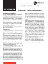
Figure 1.1
PIP Series
Modules
IN USE/
CONDUCTOR
LINK/
ACTIVITY
tm
ANALOG AUDIO INPUTS
TCP / IQ
PIP-Lite
Analog
PIP-USP3
DSP-based
PIP-USP3/CN
DSP-based
Works with CobraNet
136763-7_4-08_networked_pip-series_reference_manual.fm Page 9 Monday, March 17, 2008 11:17 AM

Networked PIP Series
page 10
Reference Manual
1.1 Unpacking
The unit is shipped in a protective antistatic bag. CAUTION: STATIC ELECTRICITY
MAY DAMAGE THE UNIT. Use caution when handling the unit. Carefully ground your-
self BEFORE touching the unit. Avoided unnecessary touching the components or solder
pads on the circuit board. It is best to handle the unit by its front panel only.
Please unpack and inspect the unit for damage that may have occurred during transit. If
damage is found, notify the transportation company immediately. Only the consignee may
initiate a claim with the carrier for shipping damage. Crown will be happy to cooperate fully
as needed. Save the shipping carton as evidence of damage for the shipper's inspection.
Even if the unit arrived in perfect condition, as most do, save all the packing materials.
NEVER SHIP THE UNIT WITHOUT THE FACTORY PACK.
1.2 How to Use This Manual
This manual provides you with the necessary information to safely and correctly set up and
operate your amplifier accessory. It does not cover every aspect of installation, setup or
operation that might occur under every condition. For additional information, please con-
sult Crown Tech Support, your system installer or retailer.
We strongly recommend that you read all instructions, warnings and cautions contained in
this manual. Also, for your protection, please send in your warranty registration card today,
or register online at www.crownaudio.com. And save your bill of sale – it’s your official
proof of purchase.
136763-7_4-08_networked_pip-series_reference_manual.fm Page 10 Monday, March 17, 2008 11:17 AM

page 11
Reference Manual
Networked PIP Series
2 Controls, Indicators and Connectors
Figure 2.1 PIP-Lite Front Panel Controls, Indicators and Connectors
(Note: Actual Product Artwork May Vary Slightly)
ANALOG AUDIO INPUTS
TCP / IQ
A. Balanced Audio Input Connectors
3-pin removable barrier-strip connectors, one per channel.
B. Preset Indicator
Signals the number of the current preset, if active, by flashing a series of flashes equal to
the current preset number. See Section 4.1.2.
C. Reset/Preset Switch
Used to change presets, restore settings to factory default or restore all the presets to the
factory defaults. During operations of the switch, the Data indicator flashes as an aid to
the user. See Section 4.1.11.
D. Data Indicator
Flashes when the PIP-Lite receives a valid command that is addressed to the PIP-Lite.
See Section 4.1.1.
E. AUX Connector
AUX input, AUX output, and Listen Bus. See Section 6.1.
F. Network Connector
The network connector is a standard RJ-45 connector that allows the PIP-Lite to connect
to an Ethernet network. Connection is made using a standard Category 5 or better cable
to a network switch port. For compliance with emission regulations, the supplied ferrite
core must be placed on the CAT5 cable, with the cable making two passes through the
core as shown in Figure 2.2. The Link Activity LED indicates data activity on the network
line. The 100 MB LED indicates that the data is at 100 Megabits. See Section 4.1.3.
G. Mounting Holes
2.1 PIP-Lite
Figure 2.2 Pass the CAT5
Cable Twice Through the
Supplied Ferrite Core
136763-7_4-08_networked_pip-series_reference_manual.fm Page 11 Monday, March 17, 2008 11:17 AM

Networked PIP Series
page 12
Reference Manual
2.2 PIP-USP3
Figure 2.3 PIP-USP3 Front Panel Controls, Indicators and Connectors
(Note: Actual Product Artwork May Vary Slightly)
Please refer to Figure 2.3.
A Balanced Audio Input Connector
3-pin removable barrier strip connector for each audio channel.
B. AUX Connector
AUX input, AUX output, and Listen Bus.
C. Preset Indicator
Signals the number of the current preset, if active, by flashing a series of flashes equal to
the current preset number. See Section 4.1.2.
D. Reset/Preset Switch
Used to change presets, restore settings to factory default or restore all the presets to the
factory defaults. During operations of the switch, the Data indicator flashes as an aid to the
user. See Section 4.1.11.
E. Data Indicator
Flashes when the PIP-USP3 receives a valid command that is addressed to the PIP-USP3.
See Section 4.1.1.
F. Network Connector
The network connector is a standard RJ-45 connector that allows the PIP-USP3 to connect
to an Ethernet network. Connection is made using a standard Category 5 cable to a network
switch port. The Link Activity LED indicates data activity on the network line. The 100 MB
LED indicates that the data is at 100 Megabits. See Section 4.1.3.
G. Mounting Holes
136763-7_4-08_networked_pip-series_reference_manual.fm Page 12 Monday, March 17, 2008 11:17 AM

page 13
Reference Manual
Networked PIP Series
2.3 PIP-USP3/CN
Figure 2.4 IQ-PIP-USP3/CN Front Panel Controls, Indicators and Connectors
(Note: Actual Product Artwork May Vary Slightly)
A. Preset Indicator
Signals the number of the current preset, if active, by flashing a series of flashes equal to
the current preset number. See Section 4.1.2.
B. Reset/Preset Switch
Used to change presets, restore settings to factory default or restore all the presets to the
factory defaults. During operations of the switch, the Data indicator flashes as an aid to
the user. See Section 4.1.11.
C. Data Indicator
Flashes when the PIP-USP3/CN receives a valid command that is addressed to the PIP-
USP3/CN. See Sections 5.1.4 and 5.1.7.
D: Fan Vent
E. Mounting Holes
F. Balanced Audio Input Connector
Single 5-pin removable barrier-strip connector for both channels.
G. AUX Connector
AUX input or AUX output. Listen Bus is available through CobraNet.
H, I. Network Connectors
The dual RJ-45 CobraNet connectors allow a Primary & Secondary connection to the
100Mb Ethernet network. Should the Primary connection (H) lose Link activity with the
network, the USP3/CN will automatically switch to the Secondary connection (I) to
ensure uninterrupted audio and control. The indicators on the RJ-45 connectors display
network information concerning the Ethernet and CobraNet connections. See Sections
5.1.4, 5.1.6 and 5.1.7.
IN USE/
CONDUCTOR
LINK/
ACTIVITY
tm
136763-7_4-08_networked_pip-series_reference_manual.fm Page 13 Monday, March 17, 2008 11:17 AM

Networked PIP Series
page 14
Reference Manual
3 Installation
Before beginning, please carefully note:
CAUTION: STATIC ELECTRICITY MAY DAMAGE THE UNIT. Use caution when han-
dling the unit. Carefully ground yourself BEFORE touching the unit. Avoided unnecessary
touching the components or solder pads on the circuit board. It is best to handle the unit by
its front panel only.
3.1 Prepare the PIP
The PIP comes ready to install in the amplifier. This unit does not require setting the “IQ
address” as the older current loop, Crown bus, units did. Each PIP (as well as all network
components) comes preprogrammed with a unique network (MAC) address. The IQ or HiQ-
net address is then set (automatically or manually) via the IQwic or SystemArchitect control
software. (Also you will set a TCP/IP network address.)
3.2 Prepare the Amplifier
Turn down the amplifier level controls (full counterclockwise) and turn off the
amplifier.
Disconnect the amplifier's power cord.
Remove the existing PIP module from the amplifier back panel (two screws). This may
involve disconnecting the PIP module from a PIP2 input adapter. If a PIP2 input adapter is
present, remove ribbon cables from the adapter.
136763-7_4-08_networked_pip-series_reference_manual.fm Page 14 Monday, March 17, 2008 11:17 AM

page 15
Reference Manual
Networked PIP Series
3.3 Install the PIP Into the Amplifier
Carefully ground yourself to the chassis of
the amplifier before installing the PIP. It is a good
idea to maintain ground contact between yourself
and the amplifier while inserting the module into
the amplifier.
Connect the PIP module to the amplifier.
1. Turn the PIP module upside down so the ribbon
cable connectors located along the back edge on
the underside of the module can be clearly seen
(See Figure 3.1)
2. Attach the ribbon cables from the amplifier to the
ribbon-cable connectors. The 20-pin cable (A)
should connect to the connector closest to the
corner and the 18 pin cable (B) should connect
to the other connector.
Important: Be careful when attaching the ribbon
cable to the connector. Don’t pull
cables out if they are short. Applying
pressure to an improperly seated
connector could cause the keying tabs, which
ensure proper pin alignment, to break. Connect-
ing the ribbon cables with improper pin align-
ment will likely result in damage to the PIP
module.
3. Set amplifier sensitivity.
Mount the PIP module in the amplifier.
1. With both cables firmly attached, turn the PIP
back to an upright position. Verify that the cables
run untwisted between the amplifier and the PIP
module.
2. Insert the PIP module into the amplifier while
taking care not to crimp, pinch or stretch the rib-
bon cables.
3. Fasten the PIP module to the amplifier rear panel
with the two supplied mounting screws. Be sure
to use the supplied star-washers for a good
ground connection.
Figure 3.1 Installing the PIP
into the Amplifier
EXACT CONFIGURATION
OF AMPLIFIER AND RIB-
BON CABLES MAY VARY
136763-7_4-08_networked_pip-series_reference_manual.fm Page 15 Monday, March 17, 2008 11:17 AM

Networked PIP Series
page 16
Reference Manual
3.4 Install the Wiring
IMPORTANT: Please read the wiring rules below before installing the wiring. If your com-
puter does not communicate with the network devices after installation and addressing,
re-read this section, as well as Section 4.2 on addressing rules.
3.4.1 Wiring Rules
• Connect each device to the network through its own cable in a Star Network. Do not con-
nect them in a serial fashion (as was done with the previous IQ current loop method).
• Make sure each device has its own Category 5 certified cable connecting it to a central
concentrator, most often a switch.
Detailed instructions follow on the next page.
136763-7_4-08_networked_pip-series_reference_manual.fm Page 16 Monday, March 17, 2008 11:17 AM

page 17
Reference Manual
Networked PIP Series
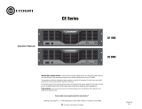
3.4.2 Wiring Instructions
1. PIP-Lite and PIP-USP3 ONLY: Using a standard CAT5 cable, connect the network con-
nector to a 100 Mb port on an Ethenet switch that is used to form the control network. For
more detail see Section 6.2, Network Basics. If the PIP module is not to be connected to a
control network, it can be temporaily connected to a computer’s Ethernet port with a crossover
cable (TX and RX pairs switched) to set up the PIP module for desired operation.
PIP-USP3/CN ONLY: Using a standard CAT5 cable, connect the Primary CobraNet connec-
tor to a 100Mb port on the Ethernet switch that is used to form the CobraNet network. For
more detail, see Section 4.1.3. We highly recommend that the CobraNet be a standalone or
separate-network LAN. If network redundancy is required, use a standard CAT5 cable to con-
nect the Secondary CobraNet connector to a 100Mb port on the auxiliary CobraNet network.
HiQnet and TCP/IQ control is also available over the CobraNet network using Harman Pro
System Architect or IQWic software.
Computer
Laptop
100Mb Switch
PIP-Lite
PIP-USP3
PIP-USP3/CN
PIP-Lite
PIP-Lite
PIP-Lite
PIP-Lite
PS8810
Figure 3.2 Network Wiring
136763-7_4-08_networked_pip-series_reference_manual.fm Page 17 Monday, March 17, 2008 11:17 AM

Networked PIP Series
page 18
Reference Manual
2. Connect the Audio Input Wiring. The PIP module is equipped with removable barrier block
connectors for each channel’s input. See Section 5.1 for more detail on audio wiring. The
USP3/CN allows the use of standard balanced audio inputs to act either as CobraNet
backup, an emergency override of CobraNet audio, or as an audio input to the CobraNet
network. See Section 5.1.6 for additional details. The single 5-pin removable barrier block
connector allows both audio channels to be inserted into the USP3/CN, then routed via
software control.
3. Connect the AUX wiring if used. See Section 7.1 for more information.
4. Reconnect the amplifier's power cord.
136763-7_4-08_networked_pip-series_reference_manual.fm Page 18 Monday, March 17, 2008 11:17 AM

page 19
Reference Manual
Networked PIP Series
4.1 Introduction
Before you set up a TCP/IP network with addressing, it’s important to understand all the
terms involved. The following glossary explains network terminology.
4.1.1 Glossary
Network: A group of interconnected components, such as a central computer, network
switching equipment, and other computers or devices.
TCP/IP network: A network made of a computer, network switching equipment, and other
network devices such as network PIP cards plugged into power amps that communicate
using TCP and IP protocols.
Subnet: A small network within a larger network. For example, a control network might be
a subnet of a venue's network, which could include computers throughout the building. Or
an audio network might be divided into subnets. For example, one audio subnet might be
for the house system and another audio subnet might be for the paging system.
IP address: An identifier for a computer or device on a TCP/IP network. Each device in a
network has its own IP address to identify it. Example: 126.126.17.42. Networks using the
TCP/IP protocol route messages based on the IP address of the destination. An IP address
is made of four numbers separated by periods. Each number can be zero to 255. Typically
the last number should never be a zero or 255. For example, 126.126.17.1 could be an IP
address. 126.126.17.0 would not be a typical IP address.
A TCP/ IP or IP address has two parts: the NETWORK ID and the HOST ID. The NETWORK
ID identifies the network, and the HOST ID identifies either the subnet and device, or just
the device if there is no subnet.
The subnet mask is a code that indicates which part of the TCP/IP address is the NET-
WORK ID and which part is the HOST ID. In subnet-mask code, 255 means "This part of the
address is the NETWORK ID".
Example:
Suppose the IP ADDRESS of a device is 126.126.17.42
and the SUBNET MASK is 255.255.0.0.
That means, (126.126) is the NETWORK ID. The remaining set of numbers (17.42) is the
HOST ID.
4 How to Set Up TCP/IP
136763-7_4-08_networked_pip-series_reference_manual.fm Page 19 Monday, March 17, 2008 11:17 AM

Networked PIP Series
page 20
Reference Manual
If your audio network stands alone (it is not part of a larger network ) then the HOST ID
identifies each device in the network.
If your audio network is part of a venue's larger network, your network is actually a sub-net-
work or subnet. In this case, the HOST ID can be further divided into two or more parts. The
first part is the SUBNET ID. The other part is the DEVICE ID. The first part of the HOST ID
identifies the subnet of your audio system, and the remaining part identifies the particular
device within that subnet.
So in this case, a complete IP address is in the form
NETWORK ID - SUBNET ID - DEVICE ID.
All devices in the network have the same network ID. All devices in a subnet have the same
subnet ID.
There are many resources available on the Internet for IP and subnet calculation. For a
stand-alone system, Crown has provided a worksheet of a tested configuration later in this
section.
DHCP (Dynamic Host Configuration Protocol): This a protocol for automatically
assigning IP addresses to devices on a network. With dynamic (DHCP) addressing, a
device might have a different IP address every time it connects to the network. If a computer
is NOT connected to a network with a DHCP server, the computer will place a default net-
work ID into the TCP/IP address and Subnet Masks.
DHCP is available with Firmware version 2.0 or higher. It requires Harman Pro System
Architect to configure.
136763-7_4-08_networked_pip-series_reference_manual.fm Page 20 Monday, March 17, 2008 11:17 AM
Page is loading ...
Page is loading ...
Page is loading ...
Page is loading ...
Page is loading ...
Page is loading ...
Page is loading ...
Page is loading ...
Page is loading ...
Page is loading ...
Page is loading ...
Page is loading ...
Page is loading ...
Page is loading ...
Page is loading ...
Page is loading ...
Page is loading ...
Page is loading ...
Page is loading ...
Page is loading ...
Page is loading ...
Page is loading ...
Page is loading ...
Page is loading ...
Page is loading ...
Page is loading ...
Page is loading ...
Page is loading ...
Page is loading ...
Page is loading ...
Page is loading ...
Page is loading ...
Page is loading ...
Page is loading ...
Page is loading ...
Page is loading ...
Page is loading ...
Page is loading ...
Page is loading ...
Page is loading ...
Page is loading ...
Page is loading ...
Page is loading ...
Page is loading ...
Page is loading ...
Page is loading ...
Page is loading ...
Page is loading ...
/