Emerson Process Management 755R User manual
- Category
- Oxygen Equipment
- Type
- User manual
This manual is also suitable for

Instruction Manual
748213-S
April 2002
http://www.processanalytic.com
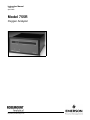
Model 755R
Oxygen Analyzer

Emerson Process Management
Rosemount Analytical Inc.
Process Analytic Division
1201 N. Main St.
Orrville, OH 44667-0901
T (330) 682-9010
F (330) 684-4434
e-mail: [email protected]
http://www.processanalytic.com
ESSENTIAL INSTRUCTIONS
READ THIS PAGE BEFORE PROCEEDING!
Rosemount Analytical designs, manufactures and tests its products to meet many national and
international standards. Because these instruments are sophisticated technical products, you
MUST properly install, use, and maintain them to ensure they continue to operate within their
normal specifications. The following instructions MUST be adhered to and integrated into your
safety program when installing, using, and maintaining Rosemount Analytical products. Failure to
follow the proper instructions may cause any one of the following situations to occur: Loss of life;
personal injury; property damage; damage to this instrument; and warranty invalidation.
•
Read all instructions prior to installing, operating, and servicing the product.
•
If you do not understand any of the instructions, contact your Rosemount Analytical representative
for clarification.
•
Follow all warnings, cautions, and instructions marked on and supplied with the product.
•
Inform and educate your personnel in the proper installation, operation, and maintenance of
the product.
•
Install your equipment as specified in the Installation Instructions of the appropriate
Instruction Manual and per applicable local and national codes. Connect all products to the
proper electrical and pressure sources.
•
To ensure proper performance, use qualified personnel to install, operate, update, program, and
maintain the product.
•
When replacement parts are required, ensure that qualified people use replacement parts specified by
Rosemount. Unauthorized parts and procedures can affect the product’s performance, place the safe
operation of your process at risk, and VOID YOUR WARRANTY. Look-alike substitutions may result
in fire, electrical hazards, or improper operation.
•
Ensure that all equipment doors are closed and protective covers are in place, except when
maintenance is being performed by qualified persons, to prevent electrical shock and personal
injury.
The information contained in this document is subject to change without notice.
Teflon and Viton are registered trademarks of E.I. duPont de Nemours and Co., Inc.
Paliney No.7 is a trademark of J.M. Ney Co., Hartford, CT
SNOOP is a registered trademark of NUPRO Co.

Instruction Manual
748213-S
April 2002
Rosemount Analytical Inc. A Division of Emerson Process Management Contents i
Model 755R
TABLE OF CONTENTS
PREFACE...........................................................................................................................................P-1
Definitions ...........................................................................................................................................P-1
Intended Use Statement.....................................................................................................................P-2
Safety Summary .................................................................................................................................P-2
General Precautions For Handling And Storing High Pressure Gas Cylinders .................................P-4
Documentation....................................................................................................................................P-5
Compliances .......................................................................................................................................P-5
1-0 DESCRIPTION AND SPECIFICATIONS..............................................................................1-1
1-1 Description.............................................................................................................................1-1
1-2 Recorder Output Ranges.......................................................................................................1-1
1-3 Mounting................................................................................................................................1-1
1-4 Isolated Current Output Option .............................................................................................1-1
1-5 Alarm Option..........................................................................................................................1-2
1-6 Electrical Options...................................................................................................................1-2
1-7 Remote Range Change Option .............................................................................................1-2
1-8 Specifications ........................................................................................................................1-3
a. Performance....................................................................................................................1-3
b. Sample ............................................................................................................................1-3
c. Electrical..........................................................................................................................1-4
d. Physical...........................................................................................................................1-4
2-0 INSTALLATION ....................................................................................................................2-1
2-1 Facility Preparation................................................................................................................2-1
a. Installation Drawings.......................................................................................................2-1
b. Electrical Interconnection Diagram ...............................................................................2-1
c. Flow Diagram..................................................................................................................2-1
d. Location and Mounting....................................................................................................2-1
2-2 Calibration Gas Requirements ..............................................................................................2-2
a. Zero Standard Gas..........................................................................................................2-2
b. Span Standard Gas ........................................................................................................2-2
2-3 Sample...................................................................................................................................2-2
a. Temperature Requirements ............................................................................................2-2
b. Pressure Requirements - General ..................................................................................2-3
c. Normal Operation at Positive Gauge Pressures.............................................................2-3
d. Operation at Negative Gauge Pressures........................................................................2-4
e. Flow Rate ........................................................................................................................2-4
f. Materials in Contact with Sample...................................................................................2-4
g. Corrosive Gases .............................................................................................................2-4
2-4 Leak Test ...............................................................................................................................2-5
2-5 Electrical Connections ...........................................................................................................2-6
a. Line Power Connection...................................................................................................2-6
b. Recorder Output Selection and Cable Connections .......................................................2-6
c. Potentiometric Output .....................................................................................................2-7
d. Isolated Current Output (Optional)..................................................................................2-7
e. Output Connections and Initial Setup for Dual Alarm Option .........................................2-8
2-6 Remote Range Change Option .............................................................................................2-12

Instruction Manual
748213-S
April 2002
ii Contents Rosemount Analytical Inc. A Division of Emerson Process Management
Model 755R
3-0 OPERATION .........................................................................................................................3-1
3-1 Overview................................................................................................................................3-1
3-2 Operating Range Selection ...................................................................................................3-1
3-3 Startup Procedure .................................................................................................................3-1
3-4 Calibration..............................................................................................................................3-1
a. Calibration with Zero and Span Standard Gases ...........................................................3-1
3-5 Compensation For Composition Of Background Gas ...........................................................3-2
a. Oxygen Equivalent Value of Gases ................................................................................3-4
b. Computing Adjusted Settings for Zero and Span Controls.............................................3-4
3-6 Selection Of Setpoints And Deadband On Alarm Option......................................................3-7
3-7 Current Output Board (Option) ..............................................................................................3-7
3-8 Routine Operation .................................................................................................................3-8
3-9 Effect of Barometric Pressure Changes on Instrument Readout ..........................................3-8
3-10 Calibration Frequency ...........................................................................................................3-8
4-0 THEORY................................................................................................................................4-1
4-1 Principles of Operation ..........................................................................................................4-1
4-2 Variables Influencing Paramagnetic Oxygen Measurements ...............................................4-2
a. Pressure Effects..............................................................................................................4-2
4-3 Electronic Circuitry.................................................................................................................4-4
a. Detector/Magnet Assembly.............................................................................................4-4
b. Control Board and Associated Circuitry..........................................................................4-4
c. Power Supply Board Assembly.......................................................................................4-5
d. Isolated Current Output Board (Optional) .......................................................................4-6
5-0 CIRCUIT ANALYSIS.............................................................................................................5-1
5-1 Circuit Operation....................................................................................................................5-1
5-2 ±15 VDC Power Supply.........................................................................................................5-1
5-3 Case Heater Control Circuit...................................................................................................5-1
5-4 Detector Heater Control Circuit .............................................................................................5-6
5-5 Detector Light Source Control Circuit....................................................................................5-7
5-6 Detector with First Stage Amplifier ........................................................................................5-8
5-7 Buffer Amplifiers U8 and U10 with Associated Anticipation Function ...................................5-10
5-8 Digital Output Circuit..............................................................................................................5-10
5-9 Analog Output Circuits for Recorder and Alarms ..................................................................5-11
a. First Stage Amplifier........................................................................................................5-11
b. Second Stage Amplifier ..................................................................................................5-11
6-0 MAINTENANCE AND SERVICE ..........................................................................................6-1
6-1 Initial Checkout With Standard Gases...................................................................................6-1
a. Control Board Checkout..................................................................................................6-1
6-2 Heating Circuits .....................................................................................................................6-2
a. Case Heater Control Circuit ............................................................................................6-2
6-3 Detector/Magnet Heating Circuit ...........................................................................................6-2
6-4 Detector Check......................................................................................................................6-4
a. Source Lamp...................................................................................................................6-5
b. Photocell .........................................................................................................................6-5
c. Suspension .....................................................................................................................6-5

Instruction Manual
748213-S
April 2002
Rosemount Analytical Inc. A Division of Emerson Process Management Contents iii
Model 755R
6-5 Replacement Of Detector/Magnet Components ...................................................................6-5
a. Source Lamp...................................................................................................................6-5
b. Photocell .........................................................................................................................6-5
c. Detector...........................................................................................................................6-7
6-6 Control Board Setup ..............................................................................................................6-7
a. Power Supply Test..........................................................................................................6-7
b. Detector zero...................................................................................................................6-7
c. U4 Zero ...........................................................................................................................6-8
d. U8 Zero ...........................................................................................................................6-8
e. U10 Zero .........................................................................................................................6-8
f. Fullscale ..........................................................................................................................6-8
g. Recorder Fullscale ..........................................................................................................6-8
7-0 REPLACEMENT PARTS ......................................................................................................7-1
7-1 Circuit Board Replacement Policy .........................................................................................7-1
7-2 Matrix – Model 755R Oxygen Analyzer.................................................................................7-2
7-3 Selected Replacement Parts.................................................................................................7-3
8-0 RETURN OF MATERIAL ......................................................................................................8-1
8-1 Return Of Material .................................................................................................................8-1
8-2 Customer Service ..................................................................................................................8-1
8-3 Training..................................................................................................................................8-1
LIST OF ILLUSTRATIONS
Figure 1-1. Model 755R Oxygen Analyzer – Front Panel ........................................................ 1-1
Figure 2-1. Interconnect of Typical Gas Manifold to Model 755R............................................ 2-3
Figure 2-2. Model 755R Rear Panel ........................................................................................ 2-5
Figure 2-3. Connections for Potentiometric Recorder with Non-Standard Span ..................... 2-6
Figure 2-4. Model 755R Connected to Drive Several Current-Actuated Output Devices........ 2-7
Figure 2-5. Relay Terminal Connections for Typical Fail-Safe Applications............................ 2-8
Figure 2-6. Typical Alarm Settings ......................................................................................... 2-10
Figure 2-7. Alarm Relay Assembly Schematic Diagram ........................................................ 2-11
Figure 3-1. Control Board - Adjustment Locations................................................................... 3-3
Figure 3-2. Dial Settings for Alarm Setpoint Adjustments........................................................ 3-7
Figure 4-1. Functional Diagram of Paramagnetic Oxygen Measurement System................... 4-3
Figure 4-2. Spherical Body in Non-Uniform Magnetic Field..................................................... 4-4
Figure 4-3. Detector/Magnet Assembly.................................................................................... 4-7
Figure 5-1. Two-Comparator OR Circuit .................................................................................. 5-2
Figure 5-2. Case Heater Control Circuit................................................................................... 5-3
Figure 5-3. Ramp Generator Circuit......................................................................................... 5-3
Figure 5-4. Detector Heater Control Circuit.............................................................................. 5-6
Figure 5-5. Detector Light Source Control Circuit .................................................................... 5-7
Figure 5-6. Detector with First Stage Amplifier ........................................................................ 5-9
Figure 5-7. Buffer, Anticipation, and Digital Output Circuits................................................... 5-10
Figure 5-8. Simplified Analog Recorder Output Circuit .......................................................... 5-12
Figure 6-1. Detector/Magnet Assembly.................................................................................... 6-3
Figure 6-2. Pin/Lead Removal ................................................................................................. 6-4
Figure 6-3. Detector Optical Bench.......................................................................................... 6-4
Figure 6-4. Lamp Replacement................................................................................................ 6-6

Instruction Manual
748213-S
April 2002
iv Contents Rosemount Analytical Inc. A Division of Emerson Process Management
Model 755R
LIST OF TABLES
Table 2-1. Remote Range Switching Truth Table................................................................. 2-12
Table 3-1. Calibration Range for Various Zero-Based Operating Ranges ............................. 3-4
Table 3-2. Oxygen Equivalent of Common Gases ................................................................. 3-6
DRAWINGS
(LOCATED IN REAR OF MANUAL)
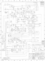
617186 Schematic Diagram, Case Board
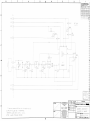
620434 Schematic Diagram, Isolated Current Output Board
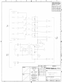
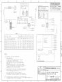
646090 Schematic Diagram, Remote Range Board
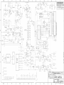
652826 Schematic Diagram, Control Board
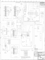
654014 Pictorial Wiring Diagram, Model 755R
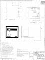
654015 Installation Drawing, Model 755R
656081 Instructions, Remote Range Selection

Instruction Manual
748213-S
April 2002
Rosemount Analytical Inc. A Division of Emerson Process Management Preface P-1
Model 755R
PREFACE
The purpose of this manual is to provide information concerning the components,
functions, installation and maintenance of the 755R.
Some sections may describe equipment not used in your configuration. The user should
become thoroughly familiar with the operation of this module before operating it. Read
this instruction manual completely.
DEFINITIONS
The following definitions apply to DANGERS, WARNINGS, CAUTIONS and NOTES found throughout
this publication.
DANGER .
Highlights the presence of a hazard which will cause severe personal injury, death, or substantial
property damage if the warning is ignored.
WARNING .
Highlights an operation or maintenance procedure, practice, condition, statement, etc. If not
strictly observed, could result in injury, death, or long-term health hazards of personnel.
CAUTION.
Highlights an operation or maintenance procedure, practice, condition, statement, etc. If not
strictly observed, could result in damage to or destruction of equipment, or loss of effectiveness.
NOTE
Highlights an essential operating procedure,
condition or statement.

Instruction Manual
748213-S
April 2002
P-2 Preface Rosemount Analytical Inc. A Division of Emerson Process Management
Model 755R
INTENDED USE STATEMENT
The Model 755R is intended for use as an industrial process measurement device only. It is not intended
for use in medical, diagnostic, or life support applications, and no independent agency certifications or
approvals are to be implied as covering such application.
SAFETY SUMMARY
If this equipment is used in a manner not specified in these instructions, protective systems may be
impaired.
AUTHORIZED PERSONNEL
To avoid explosion, loss of life, personal injury and damage to this equipment and on-site
property, all personnel authorized to install, operate and service the this equipment should be
thoroughly familiar with and strictly follow the instructions in this manual. SAVE THESE
INSTRUCTIONS.
DANGER.
ELECTRICAL SHOCK HAZARD
Do not operate without doors and covers secure. Servicing requires access to live parts which can
cause death or serious injury. Refer servicing to qualified personnel.
For safety and proper performance this instrument must be connected to a properly grounded
three-wire source of power.
Optional alarm switching relay contacts wired to separate power sources must be disconnected
before servicing.
WARNING
POSSIBLE EXPLOSION HAZARD
This analyzer is of a type capable of analysis of sample gases which may be flammable. If used for
analysis of such gases, internal leakage of sample could result in an explosion causing death, per-
sonal injury, or property damage. Do not use this analyzer on flammable samples. Use explosion-
proof version instruments for analysis of flammable samples.

Instruction Manual
748213-S
April 2002
Rosemount Analytical Inc. A Division of Emerson Process Management Preface P-3
Model 755R
WARNING.
PARTS INTEGRITY
Tampering or unauthorized substitution of components may adversely affect safety of this product.
Use only factory documented components for repair.
CAUTION
PRESSURIZED GAS
This module requires periodic use of pressurized gas. See General Precautions for Handling and
Storing High Pressure Gas Cylinders, page P-4
CAUTION
TOPPLING HAZARD
This instrument’s internal pullout chassis is equipped with a safety stop latch located on the left
side of the chassis.
When extracting the chassis, verify that the safety latch is in its proper (counter-clockwise) orienta-
tion.
If access to the rear of the chassis is required, the safety stop may be overridden by lifting the
latch; however, further extraction must be done very carefully to insure the chassis does not fall
out of its enclosure.
If the instrument is located on top of a table or bench near the edge, and the chassis is extracted, it
must be supported to prevent toppling.

Instruction Manual
748213-S
April 2002
P-4 Preface Rosemount Analytical Inc. A Division of Emerson Process Management
Model 755R
GENERAL PRECAUTIONS FOR HANDLING AND STORING HIGH
PRESSURE GAS CYLINDERS
Edited from selected paragraphs of the Compressed Gas Association's "Handbook of Compressed
Gases" published in 1981
Compressed Gas Association
1235 Jefferson Davis Highway
Arlington, Virginia 22202
Used by Permission
1. Never drop cylinders or permit them to strike each other violently.
2. Cylinders may be stored in the open, but in such cases, should be protected against extremes of weather
and, to prevent rusting, from the dampness of the ground. Cylinders should be stored in the shade when
located in areas where extreme temperatures are prevalent.
3. The valve protection cap should be left on each cylinder until it has been secured against a wall or bench, or
placed in a cylinder stand, and is ready to be used.
4. Avoid dragging, rolling, or sliding cylinders, even for a short distance; they should be moved by using a
suitable hand-truck.
5. Never tamper with safety devices in valves or cylinders.
6. Do not store full and empty cylinders together. Serious suckback can occur when an empty cylinder is
attached to a pressurized system.
7. No part of cylinder should be subjected to a temperature higher than 125
°
F (52
°
C). A flame should never be
permitted to come in contact with any part of a compressed gas cylinder.
8. Do not place cylinders where they may become part of an electric circuit. When electric arc welding,
precautions must be taken to prevent striking an arc against the cylinder.

Instruction Manual
748213-S
April 2002
Rosemount Analytical Inc. A Division of Emerson Process Management Preface P-5
Model 755R
DOCUMENTATION
The following Model 755R instruction materials are available. Contact Customer Service Center or the
local representative to order.
748213 Instruction Manual (this document)
COMPLIANCES
This product satisfies all obligations of all relevant standards of the EMC framework in Australia and New
Zealand.
N
9
6

Instruction Manual
748213-S
April 2002
P-6 Preface Rosemount Analytical Inc. A Division of Emerson Process Management
Model 755R

Instruction Manual
748213-S
April 2002
Rosemount Analytical Inc. A Division of Emerson Process Management Description and Specifications 1-1
Model 755R
%
O
2
Rosemount Anal
y
tical
Model 755R
Zero Control S
p
an Control
SPANZERO
Di
g
ital Dis
p
la
y
SECTION 1
DESCRIPTION AND SPECIFICATIONS
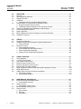
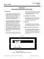
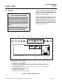
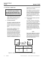
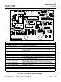
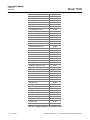
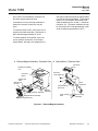
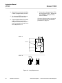
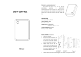
1-1 DESCRIPTION
The Model 755R Oxygen Analyzer provides
continuous readout of the oxygen content of a
flowing gas sample. The determination is
based on measurement of the magnetic sus-
ceptibility of the sample gas. Oxygen is
strongly paramagnetic while most other com-
mon gases are weakly diamagnetic.
The instrument provides direct readout of 0 to
100% oxygen concentration on a front panel
digital display. In addition, a field-selectable
voltage output is provided as standard. An
isolated current output of 0 to 20 mA or 4 to
20 mA is obtainable through plug-in of an op-
tional circuit board. Current and voltage out-
puts may be utilized simultaneously if desired.
An alarm option is also available by way of a
relay assembly that mounts at the rear of the
case with a cable that plugs into the Control
Board. Customer connections are available on
this assembly.
The basic electronic circuitry is incorporated
into two master boards designated the Control
Board assembly and the Power Supply Board
assembly. The Control Board has receptacles
that accept optional plug-in current output
board and alarm features.
1-2 RECORDER OUTPUT RANGES
Seven zero-based ranges are available with
the Model 755R: 0 to 1%, 0 to 2.5%, 0 to 5%, 0
to 10%, 0 to 25%, 0 to 50%, and 0 to 100%.
Each range is jumper selectable.
1-3 MOUNTING
The Model 755R is a rack-mounted instru-
ment, standard for a 19-inch relay rack (Refer
to IEC Standard, Publication 297-1, 1986).
1-4 ISOLATED CURRENT OUTPUT OPTION
An isolated current output is obtainable by
using an optional current output board, either
during factory assembly or subsequently in
the field. The board provides ranges of 0 to 20
or 4 to 20 mA into a maximum resistive load
of 1000 ohms.
Figure 1-1. Model 755R Oxygen Analyzer – Front Panel

Instruction Manual
748213-S
April 2002
1-2 Description and Specifications Rosemount Analytical Inc. A Division of Emerson Process Management
Model 755R
1-5 ALARM OPTION
The alarm option contains:
•
An alarm circuit incorporating two com-
parator amplifiers, one each for the
ALARM 1 and ALARM 2 functions. Each
amplifier has associated setpoint and
deadband adjustments. Setpoint is ad-
justable from 1% to 100% of fullscale.
Deadband is adjustable from 1% to 20%
of fullscale.
•
An alarm relay assembly, containing two
single-pole, double-throw relays (one
each for the ALARM 1 and ALARM 2
contacts). These relays may be used to
drive external, customer-supplied alarm
and/or control devices.
1-6 ELECTRICAL OPTIONS
The analyzer is supplied, as ordered, for op-
eration on either 115 VAC, 50/60 Hz or 230
VAC, 50/60 Hz.
1-7 REMOTE RANGE CHANGE OPTION
This option allows the customer to remotely
control the recorder scaling. It disables the
internal recorder fullscale range select without
affecting the front panel display.

Instruction Manual
748213-S
April 2002
Rosemount Analytical Inc. A Division of Emerson Process Management Description and Specifications 1-3
Model 755R
1-8 SPECIFICATIONS
1
a. Performance
Operating Range (Standard)......... 0 to 5, 0 to 10, 0 to 25, 0 to 50, and 0 to 100% oxygen
Operating Range (Optional) .......... 0 to 1, 0 to 2.5, 0 to 5, 0 to 10, 0 to 25, 0 to 50, and 0 to 100%
oxygen
Response Time ............................. 90% of fullscale, 20 seconds
Reproducibility............................... 0.01% oxygen or ±1% of fullscale, whichever is greater
Ambient Temperature Limits ......... 32°F (0°C) to 113°F (45°C)
Zero Drift........................................ ±1% fullscale per 24 hours, provided that ambient temperature
does not change by more than 20°F (11.1°C)
±2.5% of fullscale per 24 hours with ambient temperature change
over entire range
Span Drift....................................... ±1% fullscale per 24 hours, provided that ambient temperature
does not change by more than 20°F (11.1°C)
±2.5% of fullscale per 24 hours with ambient temperature change
over entire range
b. Sample
Dryness ......................................... Sample dewpoint below 110°F (43°C), sample free of entrained
liquids.
Temperature Limits ....................... 50°F (10°C) to 150°F (65°C)
Operating Pressure ....................... Maximum: 10 psig (68.9 kPa)
....................................................... Minimum: 5 psig vacuum (34.5 kPa vacuum)
Flow Rate ...................................... 50 cc/min. to 500 cc/min.
....................................................... Recommended 250 ±20 cc/min.
Materials in Contact with Sample.. Glass, 316 stainless steel, titanium, Paliney No. 7, epoxy resin,
Viton-A, platinum, nickel, and MgF2
1
Performance specifications are measured at recorder output and are based on constant sample pressure and deviation from
set flow held to within 10% or 20 cc/min., whichever is smaller.

Instruction Manual
748213-S
April 2002
1-4 Description and Specifications Rosemount Analytical Inc. A Division of Emerson Process Management
Model 755R
c. Electrical
Supply Voltage and Frequency
(selectable when ordered)............ Standard: 115 VAC ±10 VAC, 50/60 Hz
Optional: 230 VAC ±10 VAC, 50/60 Hz
Power Consumption ...................... Maximum: 300 watts
Outputs .......................................... Standard: Field selectable voltage output of 0 to 10mV, 0 to
100mV, 0 to 1V, or 0 to 5VDC
Optional: Isolated current output of 0 to 20mA or 4 to 20mA (with
Current Output Board)
Alarm Option.................................. High-Low Alarm
Contact Ratings ..................... 5 amperes, 240V AC, resistive 3 amperes, 120 VAC inductive
1 amperes, 24V DC, resistive 5 amperes, 30 VDC resistive
5 amperes, 120V AC, resistive 3 amperes, 30 VDC inductive
Setpoint ......................................... Adjustable from 1% to 100% of fullscale
Deadband ...................................... Adjustable from 1% to 20% of fullscale (Factory set at 10% of
fullscale)
d. Physical
Mounting........................................ 19 inch rack (IEC 297-1, 1986)
Case Classification........................ General Purpose
Weight ........................................... 46 lbs. (21 kg)
Dimensions.................................... 19.0 x 8.7 x 19.2 inches (482.2 x 221 x 487 mm) W x H x D

Instruction Manual
748213-S
April 2002
Rosemount Analytical Inc. A Division of Emerson Process Management Installation 2-1
Model 755R
SECTION 2
INSTALLATION
2-1 FACILITY PREPARATION
Observe all precautions given in this section
when installing the instrument.
a. Installation Drawings
For outline and mounting dimensions, gas
connections, and other installation infor-
mation, refer to Installation Drawing
654015 at the back of this manual.
b. Electrical Interconnection Diagram
Electrical interconnection is also shown in
drawing 654015. Refer also to Section 2-
5, page 2-6.
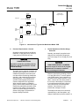
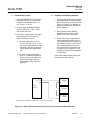
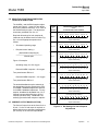
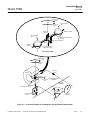
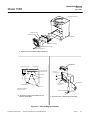
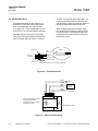
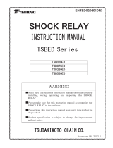
c. Flow Diagram
The flow diagram of Figure 2-1 (page 2-3)
shows connection of a typical gas selector
manifold to the Model 755R.
d. Location and Mounting
Install the Model 755R only in a
non-hazardous, weather-protected area.
Permissible ambient temperature range is
32°F to 113°F (0°C to 45°C). Avoid
mounting where ambient temperature
may exceed the allowable maximum.
Magnetic susceptibilities and partial pres-
sures of gases vary with temperature. In
the Model 755R, temperature-induced
readout error is avoided by control of
temperatures in the following areas:
1. Interior of the analyzer is maintained
at 140°F (60°C) by an electrically
controlled heater and associated fan.
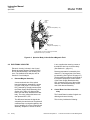
2. Immediately downstream from the
inlet port, prior to entry into the de-
tector, the sample is preheated by
passage through a coil maintained at
approximately the same temperature
as the detector (See Figure 4-3A,
page 4-7).
3. The detector is maintained at a con-
trolled temperature of 150°F (66°C).
Also, avoid excessive vibration. To mini-
mize vibration effects, the detec-
tor/magnet assembly is contained in a
shock-mounted compartment.
WARNING
POSSIBLE EXPLOSION HAZARD
This analyzer is of a type capable of analy-
sis of sample gases which may be flam-
mable. If used for analysis of such gases,
internal leakage of sample could result in
an explosion causing death, personal in-
jury, or property damage. Do not use this
analyzer on flammable samples. Use ex-
plosion-proof version instruments for
analysis of flammable samples.
Use reasonable precautions to avoid ex-
cessive vibration. In making electrical
connections, do not allow any cable to
touch the shock-mounted detector as-
sembly or the associated internal sample
inlet and outlet tubing. This precaution
ensures against possible transmission of
mechanical vibration through the cable to
the detector, which could cause noisy
readout.

Instruction Manual
748213-S
April 2002
2-2 Installation Rosemount Analytical Inc. A Division of Emerson Process Management
Model 755R
2-2 CALIBRATION GAS REQUIREMENTS
WARNING
HIGH PRESSURE GAS CYLINDERS
Calibration gas cylinders are under pres-
sure. Mishandling of gas cylinders could
result in death, injury, or property damage.
Handle and store cylinders with extreme
caution and in accordance with the manu-
facturer’s instructions. Refer to GENERAL
PRECAUTIONS FOR HANDLING & STOR-
ING HIGH PRESSURE CYLINDERS, page
P-4.
Analyzer calibration consists of establishing a
zero calibration point and a span calibration
point.
Zero calibration is performed on the range
that will be used during sample analysis. In
some applications, however, it may be desir-
able to perform span calibration on a range of
higher sensitivity (i.e., more narrow span) and
then jumper to the desired operating range.
For example, if the operating range is to be 0
to 50% oxygen, span calibration may be per-
formed on the 0 to 25% range to permit use of
air as the span standard gas.
Recommendations on calibration gases for
various operating ranges are tabulated in Ta-
ble 3-1 (page 3-4) and are explained in Sec-
tions 2-2a (page 2-2) and 2-2b (page 2-2).
Each standard gas should be supplied from a
cylinder equipped with dual-stage, metal dia-
phragm type pressure regulator, with output
pressure adjustable from 0 to 50 psig (0 to
345 kPa).
Instrument response to most non-oxygen
sample components is comparatively slight,
but is not in all cases negligible. During initial
installation of an instrument in a given appli-
cation, effects of the background gas should
be calculated to determine if any correction is
required (See Section 3-4, page 3-1).
a. Zero Standard Gas
In the preferred calibration method, de-
scribed in Section 3-4a (page 3-1), a suit-
able zero standard gas is used to
establish a calibration point at or near the
lower range limit. Composition of the zero
standard normally requires an oxy-
gen-free zero gas, typically nitrogen.
b. Span Standard Gas
A suitable span standard gas is required
to establish a calibration point at or near
the upper range limit. If this range limit is
21% or 25% oxygen, the usual span
standard gas is air (20.93% oxygen).
2-3 SAMPLE
Basic requirements for sample are:
1. A 2-micron particulate filter, inserted into
the sample line immediately upstream
from the analyzer inlet.
2. Provision for pressurizing the sample gas
to provide flow through the analyzer.
3. Provision for selecting sample, zero stan-
dard, or span standard gas for admission
to the analyzer, and for measuring the
flow of the selected gas.
a. Temperature Requirements
Sample temperature at the analyzer inlet
should be in the range of 50°F to 150°F
(10°C to 66°C).
Normally, however, a maximum entry
temperature of 110°F (43°C) is recom-
mended so that the sample temperature
will rise during passage of the sample
through the analyzer. This precaution
prevents cooling of the sample and possi-
ble analyzer-damaging condensation.
With a thoroughly dry sample, entry tem-
perature can be as high as 150°F (66°C)
without affecting readout accuracy.

Instruction Manual
748213-S
April 2002
Rosemount Analytical Inc. A Division of Emerson Process Management Installation 2-3
Model 755R
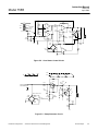
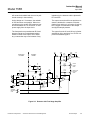
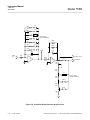
Figure 2-1. Interconnect of Typical Gas Manifold to Model 755R
b. Pressure Requirements - General
Operating pressure limits are as follows:
maximum, 10 psig (68.9 kPa); minimum,
5 psig vacuum (34.5 kPa vacuum).
CAUTION
RANGE LIMITATIONS
Operation outside the specified pressure
limits may damage the detector, and will
void the warranty.
The basic rule for pressure of sample and
standard gases supplied to the inlet is to
calibrate the analyzer at the same pres-
sure that will be used during subsequent
operation, and to maintain this pressure
during operation. The arrangement re-
quired to obtain appropriate pressure
control will depend on the application.
When inputting sample or calibration
gases, use the same pressure that will be
used during subsequent operation. Refer
to Section 2-3c (page 2-3), Normal Op-
eration at Positive Gauge Pressures, or
Section 2-3d (page 2-4) Operation at
Negative Gauge Pressures.
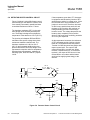
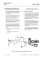
c. Normal Operation at Positive Gauge
Pressures
Normally, the sample is supplied to the
analyzer inlet at a positive gauge pres-
sure in the range of 0 to 10 psig (0 to 68.9
kPa).
CAUTION
HIGH PRESSURE GAS CYLINDERS
Pressure surges in excess of 10 psig dur-
ing admission of sample or standard
gases can damage the detector.
Maximum permissible operating pressure
is 10 psig (68.9 kPa). To ensure against
over-pressurization, insert a pressure re-
lief valve into the sample inlet line. In ad-
dition, a check valve should be placed in
the vent line if the analyzer is connected
to a manifold associated with a flare or
other outlet that is not at atmospheric
pressure. If the detector is over-
pressurized, damage will result.
The analyzer exhaust port is commonly
vented directly to the atmosphere. Any
change in barometric pressure results in a
Zero
Standard
Gas
Span
Standard
Gas
Sample In
Needle
Valves
Flowmeter
Two Micron
Filter
Model 755R
Oxygen Analyzer
To Vent

Instruction Manual
748213-S
April 2002
2-4 Installation Rosemount Analytical Inc. A Division of Emerson Process Management
Model 755R
directly proportional change in the indi-
cated percentage of oxygen.
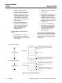
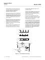
Example:
Range, 0% to 5% O
2.
Barometric pressure change after
calibration, 1%.
Instrument reading, 5% O
2
.
Readout error = 0.01 x 5% O
2
=
0.05% O
2
.
Fullscale span is 5% O
2.
Therefore, the 0.05% O
2
error is
equal to 1% of fullscale.
Thus, if the exhaust is vented to the at-
mosphere, the pressure effect must be
taken into consideration. This may be ac-
complished in various ways, including
manual computation and computer cor-
rection of data.
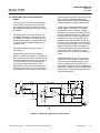
d. Operation at Negative Gauge Pres-
sures
Operation at negative gauge pressures is
not normally recommended, but may be
used in certain special applications. A
suction pump is connected to the analyzer
exhaust port to draw sample into the inlet
and through the analyzer. Such operation
necessitates special precautions to en-
sure accurate readout. First is the basic
consideration of supplying the standard
gases to the analyzer at the same pres-
sure that will be used for the sample dur-
ing subsequent operation. In addition, any
leakage in the sample handling system
will result in decreased readout accuracy
as compared with operation at atmos-
pheric pressure.
The minimum permissible operating pres-
sure is 5 psig vacuum (34.5 kPa vacuum).
Operation of the analyzer below this limit
may damage the detector, and will void
the warranty.
e. Flow Rate
Operating limits for sample flow rate are
as follows: minimum, 50 cc/min; maxi-
mum, 500 cc/min. A flow rate of less than
50 cc/min is too weak to sweep out the
detector and associated flow system effi-
ciently. Incoming sample may mix with
earlier sample, causing an averaging or
damping effect. Too rapid a flow will
cause back pressure that will affect the
readout accuracy. The optimum flow rate
is between 200 and 300 cc/min.
Deviation from the set flow should be held
to within 10% or 20 cc/min, whichever is
smaller. If deviation is held to within these
parameters and operating pressure re-
mains constant, zero and span drift will
remain within specification limits.
The analyzer should be installed near the
sample source to minimize transport time.
Otherwise, time lag may be appreciable.
For example, assume that sample is sup-
plied to the analyzer via a 100-foot
(30.5 m) length of 1/4-inch (6.35 mm)
tubing. With a flow rate of 100 cc/min,
sample transport time is approximately 6
minutes.
Sample transport time may be reduced by
piping a greater flow than is required to
the analyzer, and then routing only the
appropriate portion of the total flow
through the analyzer. The unused portion
of the sample may be returned to the
stream or discarded.
f. Materials in Contact with Sample
Within the Model 755R, the following
materials are exposed to the sample: 316
stainless steel, glass, titanium, Paliney
No.7, epoxy resin, Viton-A, platinum,
nickel and MgF
2
coating on mirror.
g. Corrosive Gases
In applications where the sample stream
contains corrosive gases, a complete
drying of the sample is desirable, as most
of these gases are practically inert when
totally dry. For corrosive applications
consult the factory.
Page is loading ...
Page is loading ...
Page is loading ...
Page is loading ...
Page is loading ...
Page is loading ...
Page is loading ...
Page is loading ...
Page is loading ...
Page is loading ...
Page is loading ...
Page is loading ...
Page is loading ...
Page is loading ...
Page is loading ...
Page is loading ...
Page is loading ...
Page is loading ...
Page is loading ...
Page is loading ...
Page is loading ...
Page is loading ...
Page is loading ...
Page is loading ...
Page is loading ...
Page is loading ...
Page is loading ...
Page is loading ...
Page is loading ...
Page is loading ...
Page is loading ...
Page is loading ...
Page is loading ...
Page is loading ...
Page is loading ...
Page is loading ...
Page is loading ...
Page is loading ...
Page is loading ...
Page is loading ...
Page is loading ...
Page is loading ...
Page is loading ...
Page is loading ...
Page is loading ...
Page is loading ...
Page is loading ...
Page is loading ...
Page is loading ...
Page is loading ...
Page is loading ...
Page is loading ...
Page is loading ...
Page is loading ...
Page is loading ...
Page is loading ...
Page is loading ...
Page is loading ...
Page is loading ...
-
 1
1
-
 2
2
-
 3
3
-
 4
4
-
 5
5
-
 6
6
-
 7
7
-
 8
8
-
 9
9
-
 10
10
-
 11
11
-
 12
12
-
 13
13
-
 14
14
-
 15
15
-
 16
16
-
 17
17
-
 18
18
-
 19
19
-
 20
20
-
 21
21
-
 22
22
-
 23
23
-
 24
24
-
 25
25
-
 26
26
-
 27
27
-
 28
28
-
 29
29
-
 30
30
-
 31
31
-
 32
32
-
 33
33
-
 34
34
-
 35
35
-
 36
36
-
 37
37
-
 38
38
-
 39
39
-
 40
40
-
 41
41
-
 42
42
-
 43
43
-
 44
44
-
 45
45
-
 46
46
-
 47
47
-
 48
48
-
 49
49
-
 50
50
-
 51
51
-
 52
52
-
 53
53
-
 54
54
-
 55
55
-
 56
56
-
 57
57
-
 58
58
-
 59
59
-
 60
60
-
 61
61
-
 62
62
-
 63
63
-
 64
64
-
 65
65
-
 66
66
-
 67
67
-
 68
68
-
 69
69
-
 70
70
-
 71
71
-
 72
72
-
 73
73
-
 74
74
-
 75
75
-
 76
76
-
 77
77
-
 78
78
-
 79
79


Emerson Process Management 755R User manual
- Category
- Oxygen Equipment
- Type
- User manual
- This manual is also suitable for
Ask a question and I''ll find the answer in the document
Finding information in a document is now easier with AI
Related papers
Other documents
-
Rosemount 755R O2 Analyzer-Rev R Owner's manual
-
-
-
-
-
-
 SUPERLED 59127 User manual
-
-
 Tsubaki ED Series User manual
-

