Page is loading ...

Assembly and Operation
®
Liquid Propane Gas Grill
Model No. 16238
@
@
I//
THIS GRILL IS FOR OUTDOOR
USE ONLY
CAUTION Read and follow all Safety Statements,
Assembly instructions, and Use
and Care Manual Directions before
attempting to assemble and cook.
CAUTION
Some parts may contain sharp edges,
wear protective gloves if necessary.
I
Failure to follow all manufacturer's
instructions could result
in serious personal injury and/or
property damage.
Customer Service
Toll Free 1-800-396-3838
To Installer/Assembler: Leave these
instructions with consumer.
To Consumer: Keep this manual for future
reference.
Sears, Roebuck and Co., Hoffman Estates, IL 60179, U.S.A
www.sears.com
SP5327A-37

Warranty ......................................................... 2
Safety. ............................................................. 2
Caring for your equipment .............................. 3
Hardware ........................................................ 6
Assembly. .................................................. 7-24
Operation ................................................. 25-26
Cleaning and Maintenance ...................... 27-28
Parts .............................................................. 29
Exploded view ............................................... 30
Troubleshooting ............................................. 31
Product Record
IMPORTANT: Fill out the product record
information below.
Model Number
UPC (on carton) Label Lot # GG
Serial Number
Date Purchased
One Year Full Warranty on Kenmore Grill
For one year from the date of purchase Sears will repair or
replace, at our option, any grill part (except for paint finish) that is
defective in material or workmanship. If this grill is defective in
material or workmanship within one year from the date of
purchase, contact Sears at 1-800-4-MY-HOME_.
Additional Warranty on Specific Grill Parts
For the time periods listed below, Sears will replace the following
specific grill parts free of charge if they are defective in material
of workmanship (Part replacement only, labor not included) :
Lifetime on Cast Aluminum Lids and Bottoms
Five years from purchase date on Stainless Burners
All warranty coverage excludes ignitor batteries and any paint
loss or rusting which are either expendable parts that can wear
out from normal use in less than a year, or are conditions that
can be the result of abnormal use, accident or improper mainte-
nance.
All warranty coverage is void if this grill is used for commercial or
rental purposes.
This warranty gives you specific legal rights, and you may also
have other rights which vary from state to state.
Sears, Roebuck and Co., Dept, 817WA, Hoffman Estates, IL 60179
Combustion byproducts produced when
using this product contain chemicals
known to the State of California to cause
cancer, birth defects, or other reproductive
harm.
IF YOU SMELL GAS:
1. Shut off gas supply to the
appliance.
2. Extinguish any open flame.
3. Open lid.
4. If odor continues, immediately
call your gas supplier or your fire
department.
iiiiiiiiiiiiiiiiiiiiiiiiiiiiiiiiiiiiiiiiiiiiiiiiiiiiiiiiiiiiiiiiiiiiiiiiiiiiiiiiiiiiiiiiiiiiiiiiiiiiiiiiiiiiiiiiiiiiiii_i_
• Do not store or use gasoline or
other flammable vapors and liquids
in the vicinity of this or any other
appliance.
• An LP cylinder not connected
for use shall not be stored in
the vicinity of this or any other
appliance.
© Sears, Roebuck and Co.
2

1
For residential use only. Do not use forl
commercial cooking,
I
CARBON MONOXIDE HAZARD
Combustion byproducts include carbon
monoxide which has no odor and can
cause serious injury or death. Never use
inside homes, vehicles or tents.
Call Grill Service Center For Help And Parts
If you have questions or need assistance during
assembly, please call 1-800-396-3838. You will be
speaking to a representative of the grill manufacturer
and not a Sears employee. To order new parts call
Sears at 1-800-4-MY-HOME ®.
GETTING FAMILIAR WITH YOUR GRILL
Oono u e our r,,,un ,, o h w eada d
understood all of the information in this manual. It
is extremely important to be sure that:
• Your grill is properly assembled.
• There are no leaks in the gas supply system
(see 'Leak Testing' section).
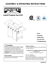
• The burner is properly assembled with the venturi tubes
seated over the valve outlets (Figure 1 below) and there
are no blockages present in the venturi tubes
(see 'Cleaning Venturi Tubes' section).
• Electrical supply cords and/or gas supply hoses are kept
away from any heated surfaces.
• Your grill is positioned in a safe location
(see 'Installation' section).
Figure 1.
• Ensure valve outlets (orifices) are assembled 3/8" (1 cm)
into the venturi tubes.
• Check to see that the valve outlets and venturi tubes are
parallel to the bottom of the base casting of your appliance.
W CASTING
Failure to ensure correct venturi tube assembly
may result in a hazardous fire or explosion
causing serious bodily injury and/or property
damage.
CARING FOR YOUR EQUIPMENT
INSTALLATION
THE INSTALLATION OF THIS APPLIANCE MUST
CONFORM WITH LOCAL CODES OR, IN THE
ABSENCE OF LOCAL CODES:
In Canada: must conform to CAN/CGA - B149.2 Propane
Installation Code or CAN/CGA B149.1 Natural Gas
Installation.
In the U.S.A.: must conform to National Fuel Gas Code
ANSI Z223.1.
When deciding where to place your appliance,
follow these minimum clearance distances to
adjacent combustible materials:
• 24 inches (61 cm) from side of unit (See Figure 2)
18 inches (46 cm) from back of unit (See Figure 2)
FOR YOUR OWN SAFETY:
• Only use your grill OUTDOORS in a well ventilated area
-- preferably 10 feet (3m) from your residence or any
outbuildings.
• Always keep the area around your grill clear of any
combustible materials, gasoline, or other flammable liquids.
• DO NOT operate this grill under overhead or unprotected
construction.
• DO NOT obstruct the
flow of combustion and
ventilation air to the grill.
• DO NOT use in garages,
sheds, breezeways, or
other enclosed areas.
• DO NOT store a spare L.E
(propane) cylinder under or
near your grill.
• DO NOT leave your
grill unattended while in
operation.
• DO NOT allow children to
operate or play near your
grill.
24"
I (61cm)
_'/ (46cml
MODEL MAY NOT BE EXACTLYAS SHOWN.
DO NOT use while under the influence of alcohol or drugs.
DO NOT install/use in or on recreational vehicles and/or
boats
ELECTRICAL CAUTION
• If any accessory installed on this grill requires an external
electrical power source, it must be electrically grounded in
accordance with local laws or in the absence of local laws,
with the Canadian Electrical Code CSA C22.1 or in the U.S.,
with the National Electrical Code ANSI-NFPA 70.
• The three-prong plug provides protection against shock
hazard and should be plugged directly into a properly
grounded three-prong receptacle. Do not cut or remove the
grounding prong from this plug.
• Ensure all electrical supply cords and fuel supply hoses are
kept well away from any heated surfaces.

L.P. GAS CYLINDER
Gas cylinders manufactured today have
mechanisms to provide worry free
grilling year round:
Q.C.C.I or Type 1-Quick Connect
Coupling Valve, ensure fast tank
hook-ups requiring only hand
tightening. The redundant
valve system inhibits the flow
of gas to the burner if the
connection is not correct.
O.RD. or Overfill Protection
Device prevents accidental
gas leaks caused by cylinder
'over-pressurization', the
leading cause of cylinder gas
leaks. The float in the tank
will automatically stop filling at
80% capacity, leaving a
20% area for the expansion
of liquid. Without this safety
feature, the relief valve may FILLING STOPS AT 80%
open and discharge propane,
creating a potential safety hazard. An O.P.D. cylinder is easily
distinguished by its triangular hand wheel valve. (Figure 3)
NEW OPD
HANDWHEEL
_hreads
1. SPECIFICATIONS
Self-contained propane gas grill systems are designed to be
used only with a 20 Ib (9.1 kg) propane cylinder, equipped with
a Type 1 cylinder valve and incorporating an overfill protection
device (O.P.D).THE CYLINDER SHOULD NOT EXCEED 18
1/2" (472 MM) IN HEIGHT AND 12 1/2" (317 MM) IN DIAMETER.
This grill cannot be connected to a #510 P.O.L type valve
(ones with left-hand threads).
The cylinder for your gas grill must be constructed and marked
in accordance with the specifications of LP. gas cylinders:
In Canada: The National Standards of Canada CAN/CSA-B339,
Cylinders, Spheres and Tubes for Transportation of
Dangerous Goods; and Commission.
In the U.S.: U.S. Department of Transportation (D.O.T.)
DO NOT CONNECT TO A PROPANE GAS CYLINDER
EXCEEDING THIS CAPACITY, OR USE A CYLINDER WITH
ANY OTHER TYPE OF VALVE CONNECTION DEVICE.
The Type 1 valve is recognizable by the large external thread on
the outlet part of the valve. Non Type 1 valves do not have
these exterior threads. Any attempt to connect a regulator, with
other than the:
i) Mating Type 1 connector (recognized by the large black
coupling nut)
or
ii) Standard #510 P.O.L. fitting, by use of adapters or any other
means.
Could result in damage, fire or injury and may negate
the important safety features designed into the Type 1 system.
The connection of a #510 P.O.L fitting will not provide the flow
control or temperature shut-off features built into the complete
Type 1 System.
THE CYLINDER MUST ALSO BE EQUIPPED WITH:
a. A shut-off valve terminating in a proper cylinder valve outlet
specified in current standards:
• Canada: CAN/CGA - 1.6a - M98 - Outdoor Gas Grills -
Amend. 1.
• U.S.: ANSI Z 21.58a-1998 OUTDOOR COOKING
APPLIANCES.
b. A listed overfilling protection device (O.P.D.).
c. A safety relief valve having direct communication with the
vapor space of the cylinder.
d. A collar to protect the tank shut off valve.
e. An arrangement for vapor withdrawal.
f. A bottom ring for mounting.
SAFETY:
• Always turn off the cylinder valve tightly when your grill is
not in use.
• Handle tank valves with care.
• Never connect an unregulated L.P. gas cylinder to your grill.
• Never store a spare cylinder under or near your grill when in
use.
• Never subject any cylinder to excessive heat or direct
sunlight.
• Always keep your in-use cylinder securely fastened in an
upright position.
• Do not insert any foreign objects into the valve outlet. You
may damage the back-check. A damaged back-check can
be the source of a leak. Leaking propane may result in
explosion, fire, severe personal injury or death.
• DO NOT fill the cylinder beyond 80% full.
If the above instructions are not followed
exactly, a fire causing death or serious injury
may occur.

2. TRANSPORTATION AND STORAGE:
WARNING: Although it is safe when used properly, careless
handling of the propane gas cylinder could result in fire,
explosion, and/or serious injury.
PROPANE GAS IS HEAVIER THAN AIR, AND WILL COLLECT IN
LOW AREAS, INCREASING THE ABOVE RISKS THEREFORE:
• ALWAYS use the cylinder
cap provided with your
cylinder whenever the
cylinder is not connected
to your grill. (Figure 4)
• DO NOT store in a
building, garage or any
other enclosed area.
Store in a well-ventilated CYLINDER
area. CAP _ STRAP
• DO NOT store near any
gas burning apparatus or
LP TANK VALVE
in any
high-heat areas such as a closed car or trunk.
• Transport and store the cylinder in an upright position -- do
not tip on its side.
• Store out of reach of children.
• DO NOT smoke while transporting a cylinder in your vehicle.
FILLING:
FOR SAFETY REASONS, IF AN OPTIONAL L.P. GAS
CYLINDER WAS SUPPLIED WITH YOUR GRILL, IT HAS
BEEN SHIPPED EMPTY. THE CYLINDER MUST BE PURGED
OF AIR AND FILLED PRIOR TO USING ON YOUR GRILL.
WHEN GETTING YOUR CYLINDER FILLED:
• Allow only a qualified UP. gas dealer to fill or repair your
cylinder.
• DO NOT allow the cylinder to be filled beyond 80% full.
• Make sure the L.P. gas dealer checks the cylinder for leaks
after filling.
If the above instructions are not followed
exactly, a fire causing death or serious injury
may occur.
HOSE & REGULATOR
PROPANE GAS MODELS:
Your grill is designed to operate
on L.R (propane) gas at a
pressure regulated at 11" water
Q.C.C.
column(2.74 kPa). A regulator
preset to this pressure is supplied
with the grill and MUST be used. REGULATOR
This regulator is equipped with Q.C.C.I
the Q.C.C. Type 1, quick connect
coupling system, which
incorporates the following safety
features: (Figure 5)
• It will not allow gas to flow until a
positive seal has been made. (Figure 6)
• It has a thermal element that will shut off the flow of gas
between 240 and 300°F (115 and150°C).
• It also has a flow-limiting device which,when activated, will
restrict the flow of gas to 10 cubic feet per hour (0.28 cubic
meters per hour).
REGULATOR
Prior to attaching the propane cylinder to the hose and regulator,
be sure the cylinder valve and the appliance valves are OFF. The
cylinder valve is turned off by rotating the handwheel (see Figure 3)
clockwise (left to right) until it stops and all appliance valves should
be in the off position. When attaching the regulator to the cylinder,
make sure that the small probe in the nipple is centered in the
mating Q.C.C. 1 cylinder valve (see Figure 6). Turn the right hand
threaded Q.C.C.1 black nut onto the valve in a clockwise motion
until there is a positive stop. DO NOT USE A WRENCH, HAND
TIGHTEN ONLY.
Should the large black thermally sensitive coupling nut be
exposed to temperatures above 240 and 300°F, it will soften
and allow the regulator probe to disengage from the cylinder
valve -- thereby shutting off the flow of gas. Should this
occur, do not attempt to reconnect the nut. Remove the entire
regulator assembly, and replace it with a new one. (See
'REPLACEMENT PARTS' section in assembly instructions or
contact us at 1-800-396-3838)
The cause of the excessive heat should be determined and
corrected before operating your grill again. The regulator probe
also contains a flow-sensing element, which will limit the flow of
gas to the regulator to a manageable amount (10 cubic feet per
hour) in the event of a hose or regulator rupture. If it is evident
that the flow control device has been activated, the cause of the
excessive flow should be determined and corrected before using
your grill again.
Please refer to the troubleshooting guide on page 34 or
contact us 1-800-396-3838.
NOTE: IMPROPER LIGHTING PROCEDURES CAN
CAUSE THE FLOW CONTROL TO ACTIVATE, RESULTING
IN REDUCED HEAT OUTPUT. IF THIS IS SUSPECTED,
RESET THE FLOW CONTROL BY SHUTTING OFF ALL
BURNER CONTROLS AND THE CYLINDER VALVE. WAIT
30 SECONDS, THEN TURN THE CYLINDER VALVE ON
EXTREMELY SLOWLY - WAIT 5 SECONDS AND TURN THE
BURNER VALVE ON AND LIGHTAS NORMAL.
• Never connect a propane gas grill to an unregulated
propane gas supply or any other gas. Do not attempt to
alter the hose or regulator in any way.
• The connection fitting must be protected when disconnected
from the propane tank. If the fitting is allowed to drag on
the ground, nicks and scratches could occur resulting in a
leak when connected to the propane tank.
PROPANE AND NATURAL GAS MODELS:
• Do not allow any grease (or other hot material) to fall onto
the hose, or allow the hose to come in contact with any hot
surfaces of the grill.
• Visually inspect the entire length of the hose assembly
before each use of the grill. If it is evident there is
excessive abrasion/wear, or the hose is cut, it must be
replaced prior to using your grill. Only the hose assembly
as specified in the Parts List should be used.
• Follow the 'LEAK TEST' instructions before lighting your
grill for the first time, every time a propane cylinder is
refilled, if any gas component is changed, if the regulator
flow-limiting device has been activated, after prolonged
periods of storage or non-use or at least once per season.

bJ
J
#2 Phillips Screwdriver
(! piece)
:r_._illivc#_._ii
&
#8-32 x 3/8 Tapping Screw
(2 pieces)
&
#10x 1F2Phillips Screw
(24 pieces)
Master Bagpack
i
i
i
i
i
i
i
i
i
i
i
i
i
i
i
i
i
i
i
i
i
i
i
i
m
1/4" - 20 X 2" Carriage Bolt
(8 pieces)
[
#6-32 Wing Nut
(Overlay)
(2 pieces)
Upper Tank Bracket
(Tank)
(! piece)
1/4" - 20 X 1/2" Carriage Bolt
(2 pieces )(Black)
A
Shoulder Screw
(2 pieces)
1/4"-20 Large Body Tapered Wing Nut
(2 pieces)
1/4"-20 Wingnut
(10 pieces)
(2 Black)
#10-24 Wing Nut Push Pin Hinge Clip
(Sideburner) (Side Panel) (Lid)
(1 piece)
(2 pieces) (1 piece)
Handle
#10-24 Wing Nut
(Handle)
(2 pieces)
1/4-3/4 Washer
(2 pieces)
#10-24 Wing Nut
(Cross Lighter)
(3 pieces)
Cross Lighter/Burner Bagpack
Q
Tube Spacer
(Cross Lighter)
(3 pieces)
1/4" - 20 X 3/4" Carriage Bolt
(Cross Lighter)
(3 pieces)
1/4"-20 Knurl Nut
(Burners)
(3 pieces)

I'l
NoTank
Bracket
%
/
Left hand leg assembly
Tank
Bracket
Right hand leg assembly
Notch
Caster Plug
FIG. "A"
1. Turn leg assembly upside down as
shown and insert caster plug.
Make sure caster plug tab is in line with
notch in leg. (SEE FIG "A")
2. Turn leg assembly over and tap on a hard surface
until the caster plugs are fully seated.
Insert caster into holes on outside
corner of caster plug as shown.
Leg Assembly
(Left Hand shown)
Locking Caster
Non-Locking Caster
3. Insert locking casters into the caster plugs on front of leg
assemblies and press in until caster is fully seated as shown.
Console mounting
tabs are on front
side of leg
assemblies.
4. Insert non-locking casters into the caster plugs
on rear of leg assembiles.

5. Position left hand leg assembly as shown with console mounting tab facing up.
Place non-tank side of bottom pan over bottom support. Attach bottom pan with
1/4"-20 x 1/2" carriage bolt (Black) and wing nut (Black).
Console mounting tab facing up.
Bottom Pan
Bottom Su
Tank opening on right side.
6. Position right hand leg assembly as shown, with console mounting tab facing up.
Place tank side of bottom pan over bottom support. Attach bottom pan with
1/4-20 x 1/2" carriage bolt and wing nut.
Console mounting tab facing up.
/
1/4"-20 Wingnut
1/4" - 20 X 1/2" Carriage Bolt
\
\

7. Position side panels over legs and slide up into position.
Bottom flange of side panel hooks over bottom support.
Push against
leg assembly
Then slide up
into position

Your Home
For repair-in your home -of all major brand appliances,
lawn and garden equipment, or heating and cooling systems,
no matter who made it, no matter who sold it!
For the replacement parts, accessories and
owner's manuals that you need to do-it-yourself.
For Sears professional installation of home appliances
and items like garage door openers and water heaters.
1-800-4-MY-HOME ® (1-800-469-4663)
Call anytime, day or night (U.S.A. and Canada)
vvvvvv.sears.com vvww.sears.ca
Our Home
For repair of carry-in items like vacuums, lawn equipment,
and electronics, call or go on-line for the location of your nearest
Sears Parts & Repair Center.
1-800-488-1 222
Call anytime, day or night (U.S.A. only)
www.sears.com
To purchase a protection agreement (U.S.A.)
or maintenance agreement (Canada) on a product serviced by Sears:
1-800-827-6655 (U.S.A.) 1-800-361-6665 (Canada)
Para pedir servicio de reparaci6n
a domicilio, y para ordenar piezas:
1-888-SU-HOGAR sM
(1-888-784-6427)
Au Canada pour service en fran_ais:
1-800-LE-FOYER Mc
(1-800-533-6937)
www.sears.ca
TM
® Registered Trademark / Trademark / SMService Mark of Sears, Roebuck and Co.
TM
® Mama Registrada / Marca de F_brica / SM Marca de Servicio de Sears, Roebuck and Co.
MC MD
Marque de commerce / Marque d6pos6e de Sears, Roebuck and Co. ® Sears, Roebuck and Co.

10. Position console/valve assembly over tabs as shown.
Locate Console on tabs as shown.
(Right side shown)
Note: Check wires from switch harness to ensure
that they are not against any sharp surfaces.
11

11. Assemble shelf support brackets by sliding shelf bracket (A) and Shelf bracket (B) together while paying
close attention to hole alignment, and attach the two with (2) #10 x 1/2" screws. Repeat for second set.
12. After joining shelf bracket (A) and (B), align holes
along bottom flange of brackets with corresponding holes
along top edge of casting support. Fasten with (2) #10 x
1/2" screws.
(Note: Bottom flanges on shelf support brackets should
point toward interior of grill.)
I
I
I
I
13. Attach second shelf support bracet using (2) #10 x 1/2"
screws.
#10 x 1/2Phillips Screw
12

14. Position left side shelf over shelf mounting brackets
15. To begin installation be sure to align large shelf (holes) with the small holes in
the shelf bracket assembly. Insert (2) #10 x 1/2" Truss head screws (phillips drive)
into largest hole on outside rear corner of shelf carefully aligning with small hole in
shelf mounting bracket. Repeat procedure for inside rear.
Rear View
Outside hole
Inside hole
16. To install shelf trim, tilt grill onto opposite shelf supports, align large
holes in shelf bracket and shelf witht the small holes in the shelf trim. Then
place (2) #10 x 1/2" truss head screws into larger holes first (underneath
shelf) and tighten securely.
Front View
/
/
17. After securing shelf trim to shelf/shelf bracket, align large hole on inside
flange with large hole in control console and small hole in casting support
bracket and insert (1) #10 x 1/2" truss head screw.
\
\
\
&
#10x 1F2Phillips Screw
13

?
18. Attach side burner lid handle, side burner lid and burner tray.
19. First begin by attaching side burner lid handle to side burner lid using (2) #10 x
112" screws.
? ?
I
I
i ?
I
I
FIG "B"
21. Third, attach side burner lid using (2) #10 Shoulder Screws,
then insert side burner into slot as shown, insert threaded stud on
bottom of side burner into slot provided. After inserting stud into
burner tray attach green ground wire and secure with a #10
wingnut. After inserting side burner into burner base insert cooking
grid by aligning legs of cooking grid with remaining holes in burner
base.
I
I
I
20. Second, attach side burner tray to side burner base using (4) #10 x
1/2" screws holes as shown. (SEE FIG "B")
#10x 1/2 Phillips Screw Shoulder Screw #10-24 Wing Nut
I
I
/f_,,,, "----- Eyelet
Green Ground Wire
14

Front View Rear View Front View
22. Attach side burner assemblies using shelf mounting procedures
as previously described. (Steps 14 & 15)
23. After attaching side burner base assembly to shelf mounting
brackets insert side burner valve into burner tube of side burner as
shown.
#10 x 1/2
Phillips
Screws
! I
I I
I
I I
I
€ !
I I
! I
I I
I I
I
I I
#10 x 1/2
Phillips Screw
Side View
Rear View
24. After inserting valve orifice into burner tube,
attach shelf trim using (3) #10 x 1/2 phillips screws.
(Steps 16 & 17)
&
#10x 1F2Phillips Screw
Burner
Tube
Orifice
Burner tube must fit over valve orifice as shown.
15

Attachsideburnervalveandbezelusing(2)#8x3/8tappingscrewsasshown.
Insertsideburnerknob.
#8 x 3/8 _,
Tapping
Screws
J
Knob
Front View
25. Position base casting down over 1/4"-20 studs and secure in place with two 1/4"-20 large
body wing nuts.
I
16
&
#8-32 x 3/8 Tapping Screw
%q
1/4"-20 Large Body Wing Nut

26. Position bottom cross lighter assembly as shown,
being sure to feed ignitor wires through the front holes
in the bottom of the base casting. Bottom cross-lighter just
"lays" loose at this stage of the assembly.
NOTE: Cross lighter top and cross lighter bottom assembly come packaged togetherwith the grillburners. These parts
should be separated prior to this step.
f
/
Left side of cross lighter.
!
17

27.Installburnersbyfeedingburnerthoughslotinthebasecastingandguidingburnertubeoverorifice
invalve,seeillustrationbelow.Secureburnerswiththree1/4"-20x3/4"carriageboltsand1/4"-20Knurlnuts.
Burner Tube
Orifice
Burner tube must fit over valve orifice as shown.
1/4" - 20 X 3/4" Carriage Bolt
Q
1/4"-20 Knurl Nut
18

28.Installthreecrosslighterspacersoverthreadedstudsinbottomcrosslighter,theninstallcrosslightertopplate.
Securewiththree#10-24wingnuts.Tabsincrosslightertopmustfitinto"grooves"ontop
ofburnersasshowninillustrationbelow.
#10-24 Wine
Cross Lighter Spacer
/
\
IMPORTANT
Tabs in cross lighter top fit
into "grooves" on top of burners.
D
Tube Spacer
#10-24 Wing Nut
19

29.InstallHeatDistributionPlatebyplacinginpositionsothatthesixsupportsrestonthesixribsin
thebasecasting.
Suppo_
I I
I I
I I
Rib in Base Casting
20
/