
Part No. GEMINI-INM B 7/02
Installation and Maintenance Instructions
Dual Gas Steam Generator & Convection Steamer
Series: Gemini Model Nos. 24CGA6.2, 24CGA10.2
1333 East 179
th
Street
Cleveland, Ohio 44110
Phone: (216) 481-4900
Fax: (216) 481 3782
24CGA6.2
24CGA10.2

FOR THE INSTALLER
IMPORTANT
IT IS IMPORTANT TO POST INSTRUCTIONS WHICH ARE TO BE FOLLOWED
IN THE EVENT THE USER SMELLS GAS. THESE INSTRUCTIONS SHOULD
BE LOCATED IN A PROMINENT LOCATION, AND BE FULLY UNDERSTOOD
BY ALL USERS OF THIS EQUIPMENT. THIS INFORMATION SHOULD BE
OBTAINED FROM YOUR LOCAL GAS SUPPLIER.
ALL SERVICE MUST BE PERFORMED BY A QUALIFIED CLEVELAND
RANGE AUTHORIZED TECHNICIAN.
The wiring diagram is located on the back of the lower front panel.
RETAIN THIS MANUAL FOR YOUR REFERENCE
FOR YOUR SAFETY
Do not store or use gasoline o
r
other flammable vapors o
r
liquids in the vicinity of this o
r
any other appliance.
WARNING
Improper installation, adjustment, alterations,
service or maintenance can cause property
damage, injury or death. Read the
installation, operating and maintenance
instructions thoroughly before installing or
servicing this equipment.
WARNING
Disconnect power before servicing

INSTALLATION AND MAINTENANCE
Gemini Dual Gas Steam Generator and Convection Steamer
Table of Contents
Chapter Page
CHAPTER 1 PRODUCT IDENTIFICATION ________________________________________ 1
A. MODEL NUMBER ________________________________________________________ 1
B. SERIAL NUMBER ________________________________________________________ 1
C. PRODUCT INFORMATION PLATE __________________________________________ 1
D. 24CGA6.2 PRODUCT VIEW _______________________________________________ 2
E. 24CGA10.2 PRODUCT VIEW _______________________________________________ 3
CHAPTER 2 INSTALLATION INSTRUCTIONS _____________________________________ 4
A. GENERAL ______________________________________________________________ 4
B. INSTALLATION OF THE STEAMER _________________________________________ 4
1. Locating the Steamer __________________________________________________ 5
a. Location and Clearance Requirements of the Steamer _____________________ 5
b. Exhaust Hood Requirements _________________________________________ 8
c. Positioning and Leveling the Steamer __________________________________ 8
2. Install Slide Racks _____________________________________________________ 8
3. Install the Free Air Vented Drain Lines _____________________________________ 9
4. Install Gas Supply Lines ________________________________________________ 10
a. Gas Supply Requirements ___________________________________________ 10
b. Install Gas Supply Lines ____________________________________________ 10
c. Testing Gas Supply Lines ___________________________________________ 11
5. Install Electric Power Lines _____________________________________________ 11
6. Water Supply Requirements and Installation ________________________________ 12
a. Water Supply Requirements _________________________________________ 12
b. Setting the Descale Required Light ____________________________________ 13
c. Install Water Supply Lines ___________________________________________ 15
d. Testing Water Supply Lines __________________________________________ 16
C. STARTUP AND CHECKOUT _______________________________________________ 16
1. Installation Checkout __________________________________________________ 17
2. Burner Ignition Test (Lighting and Shutdown Instructions) ______________________ 18
a. Lighting Instructions ________________________________________________ 18
b. Shutdown Instructions ______________________________________________ 19
3. Start Up Test Procedure Gas Gemini ______________________________________ 19
a. Startup Procedure __________________________________________________ 20
b. Blowdown Inspection _______________________________________________ 20
c. Operating Tests and Final Checkout Procedure __________________________ 21
CHAPTER 3 PREVENTATIVE MAINTENANCE AND TROUBLESHOOTING ____________ 23
A. MAINTENANCE _________________________________________________________ 23
1. Maintenance Records __________________________________________________ 23
2. Yearly Maintenance ___________________________________________________ 24
B. TROUBLESHOOTING GUIDE ______________________________________________ 24

1
CHAPTER 1 PRODUCT IDENTIFICATION
Cleveland Range, Inc. assigns two product identification numbers to each steamer: a model number and a
serial number. The model number identifies the product characteristics. The serial number identifies the
individual unit.
A. MODEL NUMBER
This manual covers the Gemini Model No. 24CGA6.2 and 24CGA10.2 Dual Steam Generator and
Convection Steamer.
Each character of this model number identifies a characteristic of the steamer. The Gemini Model No.
24CGA10.2 is 24 inches wide, a Convection steamer, Gas powered, and an Atmospheric steam generator
with a capacity for 10 cooking pans, this model has the extra suffix “.2” to differentiate it from our standard
10 pan model that does not have two separate generators. This manual covers all standard features and
options available on Gemini gas steamers.
Other than selection of options, there are presently no significant design, parts, or operating differences
among steamers with this model number. Figures 1-2 and 1-3 illustrate the two Gemini designs of gas fired
steamers and identifies their major components.
B. SERIAL NUMBER
During manufacture, Gemini Steamers are assigned individual serial numbers. Whenever any inquiry is
made with Cleveland Range regarding a steamer the serial number should be referenced.
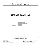
C. PRODUCT INFORMATION PLATE
The Product Information Plate on the left side of the unit lists the model and serial number of the steamer.
Refer to Figures 1-2 and 1-3 for the location of the plate. Figure 1-1 illustrates a typical Gemini Product
Information Plate. The rating plate also lists power and wiring requirements.
Figure 1-1 Gemini Product Information Plates

2
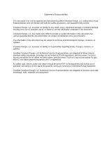
D. 24CGA6.2 PRODUCT VIEW
Figure 1-2. Gemini 6-Pan Dual Atmospheric Steam Generator
and Convection Steamer
FLUE OUTLET
WATER LEVEL PROBE HOUSINGS
LEFT- LOWER COMPARTMENT
RIGHT- UPPER COMPARTMENT
DESCALING
PORTS
AIR VENTS
CONTROL PANEL
(UPPER)
RIGHT SIDE
SERVICE
PANEL
DRIP TRA
Y
POWER ON/OFF
CONTROLS
PRODUCT INFO.
PLATE ON LEFT
ACCESS PANEL
CONTROL PANEL
(LOWER)
RIGHT SIDE
SERVICE PANEL
NOTE: NOT ALL DETAILS ARE SHOWN
MAIN
CONTROL
DRAWER
FRONT ACCESS PANEL
WIRING DIAGRAMS ARE
LOCATED ON THE BACK OF
FRONT ACCESS PANEL

3
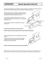
E. 24CGA10.2 PRODUCT VIEW
Figure 1-3. Gemini 10-Pan Dual Atmospheric Steam Generator
and Convection Steamer
FLUE OUTLET
WATER LEVEL PROBE HOUSINGS
LEFT- LOWER COMPARTMENT
RIGHT- UPPER COMPARTMENT
DESCALING
PORTS
AIR VENTS
CONTROL PANEL
(UPPER)
RIGHT SIDE
SERVICE
PANEL
DRIP TRA
Y
POWER ON/OFF
CONTROLS
(UPPER)
PRODUCT INFO
PLATE ON LEF
T
ACCESS PANEL
CONTROL PANEL
(LOWER)
RIGHT SIDE
SERVICE PANEL
NOTE: NOT ALL DETAILS ARE SHOWN
MAIN
CONTROL
DRAWER
FRONT ACCESS PANEL
POWER ON/OFF
CONTROL
(LOWER)
DESCALE INDICATOR
SWITCH PANEL
WIRING DIAGRAMS ARE
LOCATED ON THE BACK OF
FRONT ACCESS PANEL

4
CHAPTER 2 INSTALLATION INSTRUCTIONS
A. GENERAL
This equipment should only be installed by qualified, professional plumbers, pipe fitters, and electricians.
·
The installation of this steamer must conform with the Basic Plumbing Code of the Building Officials and
Code Administrators International, Inc. (BOCA), the National Fuel Gas Code, ANSI Z223.1-(latest
edition) or the Natural Gas Installation Code CAN/CGA-B149.1 or the Propane Installation Code
CAN/CGA-B149.2 as applicable, The National Electrical Code, ANSI/NFPA No. 70-(latest edition) or the
Canadian Electrical Code, CSA C22.2 as applicable, the Food Service Sanitation Manual of the Food
and Drug Administration (FDA) and all applicable state and local codes and regulations.
·
The installation instructions must be read in their entirety before starting the installation of this steamer.
·
To install this steamer, the following requirements must be considered when selecting a location.
a. A suitable drain must be available within 12 ft. of the steamer.
b. An electrical supply matching the power requirements found on the rating plate must be available.
c. A gas supply matching the fuel requirements found on the rating plate must be available.
d. The location must have sufficient space to meet the clearance requirements of the steamer as
outlined in Chapter 2, Section B, Part 1, “Locating the Steamer”.
e. A water supply meeting the requirements outlined in Chapter 2, Section B, Part 6 “Water Supply
Requirements and Installation” must be available.
B. INSTALLATION OF THE STEAMER
After selecting the steamer’s operating location the steamer can be positioned, and installed. After Final
Setup and Checkout, the Gemini steamer should provide years of reliable operation.
WARNING
DEATH, INJURY, AND EQUIPMENT DAMAGE could result from the
improper installation, adjustment, alteration, service or maintenance
of a steamer or installation of a unit damaged during shipment or
storage. Any of these conditions could also void the equipment
warranty.
DO NOT INSTALL a Gemini steamer that has been damaged.
Install the Gemini steamer according to the policies and procedures
outlined in this manual.

5
1. Locating the Steamer
a. Location and Clearance Requirements of the Steamer
For safe and efficient operation, observe the following criteria when selecting an operating location
for the Gemini steamer.
1) The unit should be installed in an area that is free and clear of combustible materials.
2) Do not locate the steamer directly over a floor drain.
3) A proper air supply for combustion and ventilation is critical to safe, efficient operation of Gemini
gas steamers.
4) Do not install any heat producing equipment near the air vents of the equipment. Do not block
the air vents of the unit. Do not store articles on top of the unit.
.
5) Figure 2-1 and 2-2 illustrate the dimensions and clearances required for these steamers.
Maintain the following minimum dimensions around the unit for safe and efficient operation,
maintenance and service.
·
Maintain a 3-inch operating clearance at the sides of the unit, and at least a 3-inch
clearance at the back.
·
A 12 in clearance is recommended on the right side for servicing the steamer.
·
Approximately 24 inches of clearance is recommended in front of the unit for opening the
door and standard pan clearance.
6) The steamer must be level both front to back and side to side. Select an operating surface
that is level enough to allow leveling the unit without extreme adjustment of the legs.
7) The location selected must be capable of supporting 650 lbs. for a Gemini steamer. This
includes the weight of the water and the food.
WARNING
All clearance requirements above, below, and
around the unit are the same for non-combustible
locations as for combustible locations.
CAUTION
Malfunctions and equipment damage may result from improper
mounting. Malfunctions and/or damage resulting from improper
mounting are not covered by the equipment warranty.
The steamer MUST BE LEVEL BOTH FRONT TO BACK AND
SIDE TO SIDE in all mounting arrangements.
Catastrophic damage will result from shifting the steamer more than
10
o
out of level with power supplied to the unit.

6
GAS ELECTRIC COLD WATER CLEARANCE DRAINAGE
1-1/4" IPS line size, 3/4" connection
120V-1Phase, 60 Hz. 35 PSI minimum RIGHT = 12.00" for service 1-1/2" dia.
NATURAL PROPANE BTU 2 Fans & controls 60 psi maximum SIDES = 3.00” Do not connect other
Piping 3/4" N.P.T Piping 3/4" N.P.T. 50,000
each
150 watts each (1) 3/8" dia. IPS for
Generator
REAR = 3.00” units to this drain
Supply pressure Supply pressure Generator (1) 3/8" dia. IPS for FRONT = 24.00”
4.50" W.C. Min.
14.00” W.C. Max.
11.00" W.C. Min.
14.00” W.C. Max.
100,000 total
Condenser
Drain must be vented
Do not use PVC pipe
Manufacturer must be notified if unit will
be used above 2,000 feet
Figure 2-1 Gemini 24CGA6.2 Dimensions and Clearances
OPERATING
CLEARANCE
SECONDARY
CLEARANCE

7
GAS ELECTRIC COLD WATER CLEARANCE DRAINAGE
1-1/4" IPS line size, 3/4" connection
120V-1Phase, 60 Hz. 35 PSI minimum RIGHT = 12.00" for service 1-1/2" dia.
NATURAL PROPANE BTU 2 Fans & controls 60 psi maximum SIDES = 3.00” Do not connect other
Piping 3/4" N.P.T Piping 3/4" N.P.T. 72,000
each
150 watts each (1) 1/4" dia. IPS for
Generator
REAR = 3.00” units to this drain
Supply pressure Supply pressure Generator (1) 1/4" dia. IPS for FRONT = 24.00”
4.50" W.C. Min.
14.00” W.C. Max.
11.00" W.C. Min.
14.00” W.C. Max.
144,000 total
Condenser
Drain must be vented
Do not use PVC pipe
Manufacturer must be notified if unit will
be used above 2,000 feet
Figure 2-2 Gemini 24CGA10.2 Dimensions and Clearances
OPERATING
CLEARANCE
SECONDARY
CLEARANCE

8
b. Exhaust Hood Requirements
The Gemini gas steamer MUST be installed under an exhaust hood. The exhaust hood must
extend over the gas flue opening on top of the steamer and meet the following requirements:
1). The Gemini gas steamer must be vented in accordance with all local, state and national
codes for venting gas fired appliances.
2). The exhaust hood must be sized for the cumulative ventilation requirements of all the gas-
fired appliances in the area including the Gemini. Figures 2-1 and 2-2 contains the
dimensions, gas flow, and BTU per hour data required to calculate the minimum required
hood dimensions and minimum ventilation capacity (c.f.m.) for the Gemini 6 and 10 pan
steamers.
3). Do not connect the exhaust hood directly to the flue outlet of the steamer.
4). If an existing hood cannot be used, a new one should be constructed over the steamer.
c. Positioning and Leveling the Steamer
NOTE: If there is not enough room to work on the drain, electrical, gas and water lines with the
unit in place, postpone positioning and leveling the unit until all site preparation is
completed. After the lines are prepared, position and level the steamer, then connect the
utility lines.
Move the steamer into position. Using a level, adjust the adjustable legs until the unit is level.
2. Install Slide Racks
a. Refer to Figure 2-3. Each rack has four
loops: two at the top and two at the
bottom. Hold the slide rack so the ends
of the hanger loops are towards the
cavity wall, as shown in the figure.
b. Slide one rack into the compartment with
loops toward one side.
c. Hook the loops over the top and bottom
pins.
d. Repeat steps a. through c. for the other
racks.
WARNING
INJURY AND EQUIPMENT DAMAGE could result from improper
lifting. A Gemini Steamer weighs approximately 545 pounds. Use
enough workers with experience lifting heavy equipment to place
the steamer on the supporting surface.
Figure 2- 3 Slide
Rack Installation

9
3. Install the Free Air Vented Drain Lines
Furnishing and installing the drain line is the responsibility of the owner and/or installer. Figure 2-4 illustrates
a drain layout recommended by Cleveland Range.
a. The drain lines must be installed in compliance with the Basic Plumbing Code of the Building
Officials and Code Administrators International, Inc. (BOCA), and the Food Service Sanitation
Manual of the Food and Drug Administration (FDA) and any state, provincial or local codes.
b. Do not install the steamer directly over a drain. Steam rising up out of the drain will adversely
affect operation, cooling air ventilation and may damage electrical components.
c. The total length of pipe and number of bend fittings required to reach the open drain determines
the pipe size used to extend the drain line to an open drain.
·
If the drain outlet extension requires 6 feet or less of pipe, and no more than two elbows are
required, 1- ½ inch pipe and fittings are acceptable.
·
If the drain outlet extension requires 6 to 12 feet of pipe, or requires three or more elbows,
2-inch pipe and fittings are required.
d. The drain line must have a gravity flow from the steamer
drain outlet to the floor drain. Do not install a trap in the
drain line.
e. Free air venting requires a minimum of 1 inch of
clearance between the end of the drain line and the top of
the floor drain.
f. Do not connect the steamer drain directly to drains or
plumbing of any other equipment.
g. Refer to Figure 1-2 or 1-3 depending on Model. Connect
the drain to the steamer as described below:
·
The steamer is supplied with a 1-½ -inch pipe
connection at the bottom of the unit (Figure 2-4).
·
When assembling the pipes and fittings of the drain
outlet extension, apply a hardening type pipe sealant
to the threads, and thread them together FINGER
TIGHT ONLY. DO NOT USE A WRENCH.
WARNING
DEATH, INJURY, AND EQUIPMENT DAMAGE could result from improper installation of the
drain outlet lines.
Improper installation of these lines could void the Gemini Steamers warranty. The following
restrictions are critical to the safety of personnel and equipment, and must not be violated under
any circumstances.
Do not connect the drain line into PVC or any drain material that cannot sustain 180
o
F.
Do not connect drains from any other equipment to the drain line of the Gemini Steamer.
Do not connect the drain outlet extension line directly to a floor drain or sewer line.
The drain line must be free air vented, have gravity flow from the steamer, and terminate
outside the perimeter of the unit.
DRAIN LINE
1” CLEARANCE
MINIMUM
REAR DRAIN
DRAIN
Figure 2-4 Typical Drain
Connection for Both Models
(Gemini 6-pan shown)

10
4. Install Gas Supply Lines
a. Gas Supply Requirements
1) Make sure the gas supply type matches the type of gas shown on the rating plate.
2) Make sure that the gas supply pressure does not exceed 14” water column, and falls within
the acceptable gas pressure range shown below:
·
Natural gas pressure must be between 4½” – 14” water column.
·
Propane gas pressure must be between 11” – 14” water column.
b. Install Gas Supply lines
The installer/owner is responsible for furnishing and installing the gas supply lines, valves,
regulators, and accessories. When installing the gas supply lines and accessories, observe the
following:
1). The installation must conform with local codes, or in the absence of local codes, with the
National Fuel Gas Code, ANSI Z223.1 (latest edition) or the Natural Gas Installation Code,
CAN/CGA-B149.1 or the Propane Installation Code, CAN/CGA-B149.2 as applicable.
2). THE GAS SUPPLY PRESSURE TO THE
STEAMER MUST NEVER EXCEED 14”
WATER COLUMN (½ psi). If the gas supply
pressure exceeds 14” water column; a
pressure regulator must be installed in the
gas supply plumbing to reduce the pressure
to the steamer.
3). Refer to Figure 2-5 for the recommended
layout of the gas supply lines. Refer to
Figure 2-1 or 2-2 depending on which model
you have, Detail A for the location of the ¾
inch gas inlet of the steamer.
4). Install a manual shut off valve between the
gas supply and the steamer. See Figure 2-5.
From now on this valve will be referred to as
the Main Manual gas valve.
5). It is recommended that a sediment trap (drip
leg) be installed in the gas supply line. See
Figure 2-5.
6). Use a pipe sealant compound, which is
resistant to LP gas.
Gemini
GAS MANIFOLD
CONNECTION
DRIP LEG
GAS SUPPLY
CONNECTION
A
ON
DIMENSION DIAGRAM
MAIN GAS
SUPPLY
MAIN
MANUAL GAS
SHUTOFF VALVE
PRESSURE REGULATING
VALVE (IF
REQUIRED)
Figure 2-5, Recommended
Gas Supply Line Layout

11
c. Testing Gas Supply Lines
1). Leak Testing the appliance
Before permanently turning on gas to the steamer or after any service to the gas supply, test
all pipe joints for leaks with a soap and water solution. All leaks must be corrected before
attempting to operate the steamer.
2). Pressure Testing the Gas Supply Lines
The steamer must be isolated from the gas supply system during any pressure testing as
follows:
· The appliance and its main manual shut-off valve must be disconnected
from the gas
supply piping system during any pressure testing of the system at test pressures in
excess of 14” water column (½ psi or 3.45 kPa). Be sure to leak test all fittings with a
soap and water solution after reconnecting the gas supply.
· The appliance must be isolated from the gas supply piping system by closing its main
manual shut-off valve during any pressure testing of the gas supply piping system at test
pressures equal to or less than 14” water column (½ psi or 3.45 kPa).
5. Install Electric Power Lines
The electrical supply must match the power requirements specified on the steamers rating plate and be
made in accordance with the following requirements.
a. The steamer must be grounded and have the electrical power lines installed in accordance with
local codes and/or the National Electric Code, ANSI/NFPA No. 70-LATEST EDITION (USA) or the
Canadian Electrical Code, CSA C22.2, as applicable. The wiring diagram is located on the back of
the lower front panel.
b. Optional Factory Supplied Plug
·
If a cord and plug are supplied with the unit, plug the unit into a grounded outlet dedicated to
the steamer.
·
A cord-equipped appliance will be equipped with a three-prong (grounding) plug for your
protection against shock hazard, it should be plugged directly into a properly grounded three-
prong receptacle. Do not cut off or remove the grounding prong from the plug.
WARNING
FIRE OR EXPLOSION HAZARD
LEAKING GAS CAN CAUSE FIRE OR EXPLOSION WITH PROPERTY
DAMAGE, INJURY OR LOSS OF LIFE. If the installer smells gas, or
suspects there is a gas leak, immediately refer to the posted gas leak
instructions. The posted instructions are provided by the local gas
supplier, and supersede any other instructions. Until the leak is stopped
observe the following precautions in addition to the posted instructions:
Do not light or start any appliance.
Do not touch any electrical switch.
Do not use any phone in the building.
Immediately call the gas supplier from a phone away from the building.
Follow the gas supplier’s instructions.
If the gas supplier cannot be reached call the fire department.

12
c. A main disconnect switch and a separate fuse or breaker should be installed near the unit as shown
in Figure 2-6. See Figure 2-1 or 2-2 for the steamers power requirements. Throughout the
remainder of this manual the fused disconnect switch is referred to as the main external power
switch.
d. Refer to the connection diagrams in Figure 2-7, and connect the wires to the terminal block and
ground connector accordingly.
6. Water Supply Requirements and Installation
a. Water Supply Requirements
1). Water Quality
As with any steam generating equipment, poor water quality degrades the performance of the
steamer.
Check the quality of supply water as described below before starting construction of the water
supply lines. If a water treatment system must be installed to achieve acceptable water quality,
install it before connecting the water supply lines to the Gemini Steamer.
If softened or chlorinated water is used in a Gemini steam generator, a carbon type filter must
be used for the water before it enters the steamer to remove Chlorine or other salts. If the water
supply is treated or softened either by the Water Company or on the premises, it may contain
chlorine or various salts. These additives are damaging to the steam generator. Salts and
chlorine used to soften or treat water cause rapid scale buildup, and/or increased corrosion if
allowed to flow into the steamer.
Contact a local water treatment specialist for an on-the-premises water analysis. The
recommended minimum feed water quality requirements for the steamer are listed in Table 2-1.
CAUTION
Using water not within the limits specified in this
manual could void or reduce Cleveland Range’s
warranty coverage of the steamer.
Gemin
i
DRAIN LINE
COLD WATER SUPPLY LINES
MAIN EXTERNAL
POWER SWITCH
Figure 2-6, Recommended Electrical Layout
TERMINAL
BLOCK
ELECTRICAL CONDUIT
INLET
GROUND
LUG
Figure 2-7, Electrical Connections

13
Table 2-1. Minimum Water Quality Requirements
Scale Forming Factors
Total Dissolved Solids less than 60 parts per million
Silica less than 13 parts per million
Alkalinity less than 20 parts per million
Corrosion-Causing Factors:
Free Chlorine less than 0.5 parts per million
Chloride less than 30 parts per million
PH factor greater than 7.5
2). Water Supply System
Provide a water supply system that fulfills the requirements of the limits listed in Table 2-1. The
supply must provide a minimum dynamic pressure of 35 psi (2.4 kg/cm
2
) and a maximum static
pressure of 60 psi (4.1 kg/cm
2
).
·
If analysis shows that the supply water is NOT within the required limits, either a water
treatment system and/or carbon filter must be installed in the line feeding the steam
generator or the frequency of maintenance, cleaning, and descaling must be increased
beyond that recommended in the maintenance schedule (Chapter 3). If more frequent
descaling is selected as the means of protecting the steamer from premature failure, the
“DESCALE REQUIRED” light timing should be readjusted to reflect the increased cleaning
schedule.
b. Setting the Descale Required Light
The Descale Required Light feature
tracks the number of hours the unit has
been operating since it was last reset,
and lights when it is time for descaling.
1). General
The Descale Required Light consists of
an indicator light, a solid state timer
module, and a reset/rocker switch. (The
light and reset switch consist of a single
device on the front panel identified by the
“DESCALE REQUIRED” label.) See
Figure 2-8. The timer is a digital clock
module inside the unit that keeps track of
how many hours your steamer has been
in operation since the last reset of the
timer.
DESCALE REQUIRED LIGHT/RESE
T
SWITCH. NOTE: ORIENTATION OF
SWITCH WILL VARY DEPENDING ON
MODEL
Figure 2-8 Descale Required Light
and Timer Module

14
2). Determining the Timer Setting
The recommended setting of the Descale
Required light is determined by the
quality of the water supply. Table 2-2
suggests appropriate timer settings.
3). Switches Determine Timer Setting
The Timer Module contains a bank of
miniature switches that determine the
timer setting. The switches can be placed
in either the ON or OFF positions.
Each switch has a specific value. The
total timer setting is the sum of the values
of all of the switches that are in the ON
position. (See Figure 2-9 for switch
values).
The Descale Required Light timer is
preset at the factory with switches 1 and
2 turned ON. Adding the values of these
switches results in a setting of 384 hours
(128+256=384).
4). Procedure to Change Descale Required Light Timer Switch Settings
Read this procedure completely before starting. The Descale Required Light Timer setting
should be changed only by qualified maintenance technicians familiar with electrical safety
procedures.
a) Make sure all power to the unit is OFF.
b) Determine the time you want to set.
c) Locate the timer modules, which are located horizontally in the front, at the right and left of
the electrical drawer.
d) Set the timer switches. It is a good idea to turn them all OFF first then turn ON the desired
switches.
e) Verify that the switches are in the desired position. Replace the electrical drawer cover.
WARNING
Disconnect the electrical power before servicing.
Quality of
Feed Water
Hardness
(grains/gal.)
✳
Timer
Settings
Poor 25 128 hours
Average 15 256 hours
Good 7 384 hours
Very Good 3 or less 512 hours
Suggested Timer Settings
Based on Water Quality/Hardness
✳17.1 ppm = 1 grain/gal of hardness
Table 2-2
128
256
512
1,024
ON
1 2 3 4
Switch
Values
(in Hours)
Figure 2-9 Switch Values

15
c. Install Water Supply Lines
The installer/owner is responsible for the correct water connection of the unit. When connecting the
water supply lines observe the following instructions and all national and local codes and
regulations:
1). Never
connect the unit to HOT WATER. The condenser system of the steamer will not work
properly if it is connected to HOT or WARM water.
2). The water supply should have a minimum flow pressure of 35-psi (2.4 kg/cm²) and a maximum
static pressure of 60-psi (4.1 kg/cm²). If the static pressure is above 60 psi, a pressure regulator
must be used set at approximately 50 psi. Pressure above 60 psi can damage the solenoid
valves.
3). The Gemini Steamers are supplied with two connection points for incoming water, one feeds
the condensers and the second supplies feed water to the generators. If the local water supply
is of poor quality (see Chapter 2, Section 6, Part a.1 for details of water quality), it is
recommended that treated or otherwise filtered or conditioned water be used to supply the feed
water to the generators. In the case of using a separate water supply, use the layout shown in
Figure 2-11.
4). Pay attention to the following requirements and recommendations when connecting the
steamer to the water supply:
a) Cleveland Range recommends the plumbing layout illustrated in either Figure 2-10, for
installations using a single water supply or Figure 2-11 if a separate conditioned water
supply is being used for boiler feed. Note: If using a single water feed to the system the
supply piping to the tee fitting should be of at least the next largest size of pipe to the
connection provided at the steamer.
b) The steamer has two 3/8-inch IPS fittings (Model 24CGA6.2) or two 1/4-inch IPS fittings
(Model 24CGA10.2) for the water connections to the generator and to the condenser.
These fittings are detailed as D and E in Figure 2-1 or 2-2.
c) Install a manual water valve between the main cold water supply line(s) and the steamer
supply lines.
d) The National Sanitation Foundation (NSF) requires installation of a check-valve in all supply
lines in accordance with and as required by local plumbing codes.
e) The water supply line(s) should be designed so that the unit can be moved for service.
Figure 2-10 Cleveland Range Single Water Supply Arrangement
(
*
May be installed internal to the steamer on some models)
Gemini
Steam Generator
Solenoids
Water Connection E on
Dimension Diagram
Pressure Reducer
(if required)
Main Water
Shut Off Valve
Main Cold
Water Supply
Air/Water Column
(if required)
Check Valve
Strainer
*
Condenser Solenoids
Water Connection D on
Dimension Diagram
Flow

16
Figure 2-11 Cleveland Range Single Water Supply Arrangement when Using
Separate Conditioned Feed Water Supply
(
*
May be installed internal to the steamer on some models)
f) A 40 or 50-mesh water strainer (dirt filter)
of one of the types and construction
illustrated in Figure 2-12, Cleveland
Range part number 106684 or 19870 is
supplied with the unit and should be
installed where indicated in the plumbing
layout. Note: On some Models the
strainer has already been installed as
part of the internal water piping.
·
Make sure the arrow on the strainer
body points in the direction of flow
into the steamer.
·
Install the strainer so the access nut
points down.
g) Construct all supply lines up to the point of installing the strainer. Flush the water supply
lines before connecting the strainer.
h) Apply pipe dope or Teflon tape to any threaded connection.
d. Testing Water Supply Lines
1). Check all connections for proper tightness. Remove the side panel to inspect water connections
inside the steamer.
2). Open the water supply valves.
3). Check all lines and connections for leakage, both inside and outside the steamer.
4). If Startup and Checkout will be performed next, leave the right side panel off; otherwise, replace
the side panel and secure it to the unit.
C. STARTUP AND CHECKOUT
The Startup and Checkout procedure prepares a recently installed or repaired steamer for operation. The
procedures check proper electrical, gas, water, and drain connections to the steamer, and verify basic
steamer operation.
Gemini
Water Connection E on
Dimension Diagram
Condenser Solenoids
Water Connection D on
Dimension Diagram
Pressure Reduce
r
(if required)
Main Wate
r
Shut Off Valve
Standard Cold
Water Supply
Air/Water Column
(if required)
Check Valve
Strainer
*
Flow
Conditioned Cold
Water Supply
Flow
Steam Generator
Solenoids
Figure 2-12 Water Strainer Assembly
P/N 106684
P/N 19870

17
1. Installation Checkout
Use the Installation Checklist Table 2-3, to check the overall installation.
Table 2-3. Installation Check List
TASK REFERENCE COMPLETED
Page No.
Preparation
Verify Electric Power Requirements. 6 or 7
Verify Gas Supply Requirements 10
Verify Exhaust Hood Requirements 8
Test supply water quality. 12
Check operating location clearances 6 or 7
Installation
Verify steamer is level. 8
Check drain line connection. 9
Check Exhaust Hood 8
Check electrical line connection. 11
Check water supply connection. 15
Test water supply lines. 16
Check Gas Supply Connection 10
Leak Test Gas Supply Connection 11
Check Burner Ignition Test 18
Perform Startup and checkout. 19
Notes on installation:
Page is loading ...
Page is loading ...
Page is loading ...
Page is loading ...
Page is loading ...
Page is loading ...
Page is loading ...
Page is loading ...
Page is loading ...
Page is loading ...
-
 1
1
-
 2
2
-
 3
3
-
 4
4
-
 5
5
-
 6
6
-
 7
7
-
 8
8
-
 9
9
-
 10
10
-
 11
11
-
 12
12
-
 13
13
-
 14
14
-
 15
15
-
 16
16
-
 17
17
-
 18
18
-
 19
19
-
 20
20
-
 21
21
-
 22
22
-
 23
23
-
 24
24
-
 25
25
-
 26
26
-
 27
27
-
 28
28
-
 29
29
-
 30
30


Cleveland Gemini 24CGA6.2 Installation guide
- Type
- Installation guide
- This manual is also suitable for
Ask a question and I''ll find the answer in the document
Finding information in a document is now easier with AI
Related papers
-
 Cleveland 24CGA6.2 User manual
-
 Cleveland 24CGA6.2 User manual
-
 Cleveland 42-CKEM-36 User manual
-
 Cleveland Gemini 10 Quick start guide
-
 Cleveland 24CGA10.2 User manual
-
Cleveland 36VDM Series User manual
-
Cleveland SteamCraft 21-CGA-5 User manual
-
Cleveland 36CDM16 User manual
-
Cleveland 6-CGM-200 User manual
-
Cleveland PGM-200-3 User manual


Other documents
-
 Cozy Products CL-COOP Specification
-
 Amerec AK Drip Pan "ADP" Operating instructions
-
Cleveland Range 24-CET-1 User manual
-
Estar Gemini IPS Quad 4G 8.0" User manual
-
-
Cleveland Range 24-CSM User manual
-
Cleveland Range 21-CET-8 User manual
-
-
-

