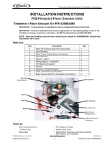
FCB Ice Probe Supplemental Harness Installation Instructions
© 2003, IMI Cornelius Inc. - 1 - Publication Number: 629088376INS
INSTALLATION INSTRUCTIONS
ICE PROBE SUPPLEMENTAL HARNESS
The following instructions should be used for installation of the Ice Probe Supplemental Harness on Pin-
nacle FCB units. Each kit will upgrade the harness for 1 main board (2 barrels).
Parts List
Tools Required
Flat Screwdriver
¼” Nut Driver
CAUTION – Only trained and certified electrical technicians should service this unit. ALL WIRING
MUST CONFORM TO NATIONAL AND LOCAL CODES.
CAUTION – This installation will be around electrical components in the control box. Use caution to
avoid electrical shock.
WARNING – HIGH VOLTAGE is present on the Inverter Board for 5 minutes after the unit is
unplugged. Working on the unit before the 5 minutes has passed may result in electrical shock or
death.
Installation Steps
Item
Number
Description Qty
1 Harness for Connector J7 1
2 Harness for Connector J18 1
1. Switch the power to the unit off or remove the fuse to the electrical power circuit breaker.
2. Lift the merchandiser to gain access to the control box front. Remove the screws that hold the con-
trol box door closed to gain access to the Main Control Board.
3. Disconnect the connector J7 from the Main Control
Board.
4. Using the provided White/Orange harness, connect
the Male end to the Main Control Board at J7 and
the Female end to the Male end of the main unit
harness J7.
Main Board
Connection
J7
Main Board
Connection
J18
Main Control Board
Main Board
Connection
J7
Main Unit
Harness J7
Release Date: November 11, 2003 www.cornelius.com Revision: A


