10
ENG
ENGLISH
ASSEMBLING AND PREPARING
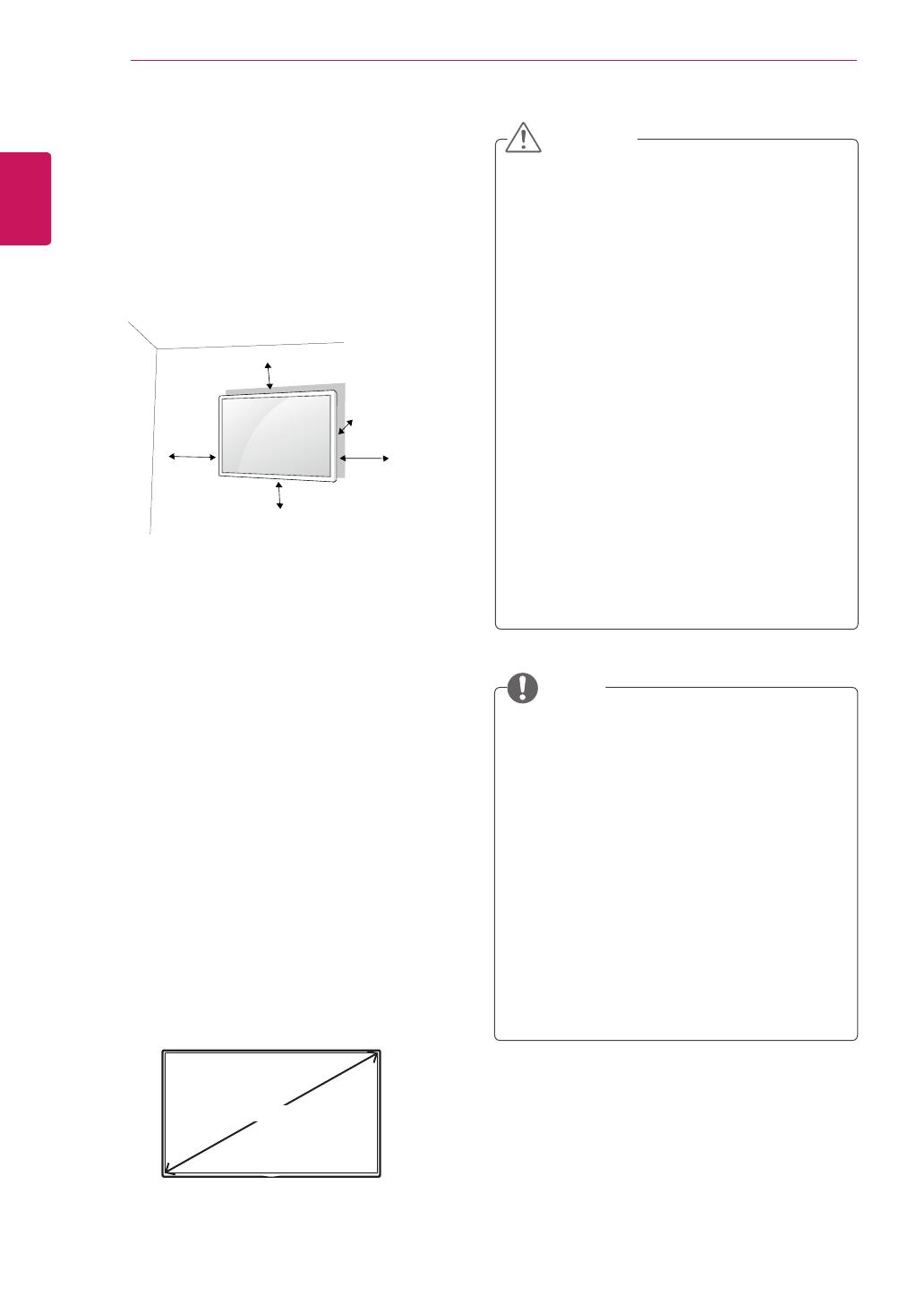
Mounting on a Wall
For proper ventilation, allow a clearance of 10
cm on each side and from the wall. Detailed
installation instructions are available from your
dealer, see the optional Tilt Wall Mounting Bracket
Installation and Setup Guide.
If you intend to mount the monitor to a wall, attach
a Wall mounting interface (optional parts) to the
back of the set.
When you install the monitor using a wall mounting
interface (optional parts), attach it carefully so it
will not fall.
1
Please, use a wall mount and screws in
accordance with VESA Standards.
2
If you use screws longer than standard, the
monitor might be damaged internally.
3
If you use improper screws, the product might
be damaged and drop from mounted position.
In this case, LG Electronics is not responsible
for damage.
4
Please use VESA standard as below.
y
785 mm or greater
* Fastening screw: Diameter 6.0 mm x Pitch 1.0
mm x Length 12 mm
y
Disconnect the power cord first, and then
move or install the monitor set. Otherwise
electric shock may occur.
y
If you install the monitor set on a ceiling or
slanted wall, it may fall and result in severe
injury.
y
Use an authorized LG wall mount and
contact the local dealer or qualified
personnel.
y
Do not over tighten the screws as this may
cause damage to the monitor set and void
your warranty.
y
Use the screws and wall mounts that meet
the VESA standard. Any damages or injuries
by misuse or using an improper accessory
are not covered by the warranty.
y
To prevent injury, this apparatus must be
securely attached to the wall in accordance
with the instrallation instructions. (This only
pertains to Australia and New Zealand.)
y
The wall mount kit includes an installation
manual and necessary parts.
y
The wall mount bracket is optional. You can
obtain additional accessories from your local
dealer.
y
The length of screws may differ depending
on the wall mount. Be sure to use the proper
length.
y
For more information, refer to the instructions
supplied with the wall mount.
y
The warranty will not cover any damages
caused by using the product in an
excessively dusty environment.
CAUTION
NOTE
785 mm
10 cm
10 cm
10 cm
10 cm
10 cm


