
Op
®
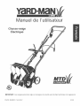
Snow Thrower
iMPORTANT: Read safety ruUes and instructions carefully before operating equipment.
PART NO. 769-00857 (8/03)

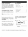
THANK YOU
Thank you for buying this quality product. This modern
outdoor power tool will provide many hours of useful
service. You will find it to be a great hbor-saving device.
This operator's manual provides you with easy-to-
understand operating instructions. Read the whole
manual and follow all the instructions to keep your new
outdoor power tool in top operating condition.
PRODUCT REFERENCES, mLLUSTRATmONS
AND SPECmFmCATmONS
All information, illustrations, and specifications in this
manual are based on the latest product information
available at the time of printing. We reserve the right to
make changes at any time without notice.
Copyright¢) 2003 MTD SOUTHWEST INC, All Rights
Reserved.
TABLE OF CONTENTS
Service Information ......................... 2
Rules for Safe Operation ..................... 3
Know Your Unit ............................ 7
Assembly Instructions ....................... 8
Operating Instructions ....................... 9
Maintenance and Repair Instructions ........... 11
Cleaning and Storage ....................... 12
Troubleshooting Chart ...................... 13
Specifications ............................. 13
Warranty Information ....................... 14
Parts List .................... inside Back Cover
SERVmCE mNFORMATmON
Service on this unit both within and after the warranty
period should be performed only by an authorized and
approved service dealer.
For service call 1-800-345-8746, or 1-800-668-1238 in
Canada to obtain a list of authorized service dealers near
you. For more details about your unit, visit our website at
If you have difficulty assembling this product or have
any questions regarding the controls, operation or
maintenance of this unit, please call the Customer
Support Department.
Before beginning, locate the unit's model plate. It lists
the model and serial numbers of your unit. Refer to the
sample plate below and copy the information for future
reference.
Me{lel Namber
Seriam_mber _ Patent Part Namber
S/N: _[[..E..._
DO NOT RETURN THE UNIT TO THE RETAILER.
PROOF OF PURCHASE WILL BE REQUIRED FOR
WARRANTY SERVICE.
Copy the model and parent
part number here:
Copy the serJaJ number
here:
Make sure you carefully read and understand this manual before starting or operating this equipment
THIS PRODUCT IS COVERED BY ONE OR MORE U.S. PATENTS. OTHER PATENTS PENDING.

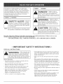
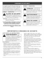
Thepurposeofsafetysymbolsistoattractyour
attentiontopossibledangers.Thesafety'symbols,
andtheirexphnations,deserveyourcarefulattention
andunderstanding.Thesafetywarningsdonotby
themselveseliminateanydanger.Theinstructionsor
warningstheygivearenotsubstitutesforproper
acddentpreventionmeasures.
SYMBOLI MEANmNG
SAFETY ALERT: Indicates
danger,
warning or caution. Attention [s required [n
order to avoid serious personal injury. May
be used [n conjunction with other symbols
or pictographs.
NOTE: Advises you of information or instructions vital to
the operation or maintenance of the equipment.
SYMBOL MEANmNG
personal injury,
WARNING: Fa,uretO obey a
safety warning can
result in injury to yourself and others.
Always follow the safety precautions to
reduce the risk of fire, electric shock and
personal injury.
. Failure to obey a
• safety warning may
result in damage or personal injury
or to others. Always follow the
safety precautions to reduce the risk of fire,
electric shock and personal injury.
Read t.he Operatgr's Mgnua[ and follow a[! warnings and safety instructions. Failure to do so can
result in serious injury to me operator ane/or oys_anaers.
FOR QUESTIONS, CALL 1o800o345o8746 IN U.S. OR 1o800o668o1238 in CANADA
IMPORTANT SAFETY INSTRUCTIONS o
READ ALL INSTRUCTIONS
WARNING: When using the unit,
you must follow the
safety rules, Please read these instructions
Please keep these instructions for later use.
Before Operating
• Read the instructions carefully. Be familiar with the
controls and proper use of the unit.
Do not operate this unit when tired, ill or under the
influence of alcohol, drugs or medication.
• Children under the age of 15 must not use the unit:
teens may operate the unit with adult guidance.
• Inspect the unit before use. Replace damaged parts.
Make sure all fasteners are in place and secure.
Replace snow thrower parts that are cracked,
chipped, or damaged in any way.
Exercise caution to avoid slipping or fal%g.
Thoroughly inspect the area where the snow thrower is
to be used. Remove all doormats, sleds, boards, wires,
debris, and other foreign objects which may be thrown
by the snow thrower.
Make sure the rotor will spin freely before using the
unit.
Dress properly. Wear adequate winter outer garments.
Wear heavy, long pants, boots, gloves and a long sleeve
shirt. Do not wear loose clothing, jeweky, short pants,
sandals or go barefoot. Secure hair above shoulder level.
Wear footwear that doesn't leak when operating the
snow thrower and that will improve footing on slippery
surfaces. Wear rubber boots.
Never attempt to make adjustments while the motor is
Let the motor and unit adjust to outdoor temperatures
before starting to clear snow.
Always wear safety ghssesishMds or goggles at all
times during operation or while performing an
adjustment or repair to protect eyes from foreign
objects that may be thrown from the machine.

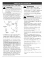
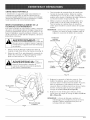
SAFETY WARNINGS FOR ELECTRIC UNITS
BANGER: Whenu%electric
machines, basic safety
precautions shouId aIways be foiIowed to reduce
the risk of fire, electric shock and personal injury.
CarefuIIy read and understand the entire
operator's manuaI before using your unit. Pay
close attention to the operating instructions and
safety warnings.
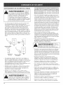
This snow mover should be grounded while in use to
protect the operator from electric shock. The snow
mover is equipped with an approved 3-conductor cord
and 3-prong grounding-type plug to fit the proper
grounding-type receptacle. The green or green/yellow
conductor in the cord is the grounding wire. Never
connect this wire to a live terminal. If your unit is for
use on less than 150 volts, it has a plug that looks like
A in the figure below. If it is for use on 150 to 250
volts, it has a plug that looks like D in the figure.
Pin
Grounding Grounding D
Means Pin
° An adapter (shown in B and C in the above figure) is
avaihble for connecting 3-prong grounding-type plugs
to 2-prong receptacles. The grounding means
extending from the adapter must be connected to a
permanent ground such as a properly-grounded outlet
box. No adapter is available for the plug shown in D.
• Use only 3-wire outdoor extension cords that have 3-
MiNiMUM WIRE SIZEFOR EXTENSION CORDS FOR
120VOLT APPLIANCES USING 0:12AMPS
I
Wire size (AWG)
CORD SETS: Please see your dealer for the
appropriate extension cord to use with this product.
Make sure your cord set is in good condition, with a
cord that is heavy enough to carry the current that
your unit will draw. An undersizedcord set will cause a
drop in line voltage resulting in a loss of power, as well
as overheating. Ihe table shown above illustrates the
WARNING: Toreducetheriskof
electrical shock, use
only SW-A, SOW-A, STOW-A, SJW-A,
SJOW-A, SJTW-A or SJTOW-A cord types.
Ground Fault Circuit Interrupter (GFCI) protection
should be provided on the circuit(s) or outlet(s) that will
be used for the unit. Use receptacles with buiR-in
GFQ protection for an extra measure of safety.
• A data plate on your unit indicates the voltage used.
Never connect the unit to an AC voltage that differs
from this voltage.
WARNING: To prevent electric
shock, use only with
an extension cord suitable for outdoor use.
• Inspect all extension cords and the unit power
connection periodically. Look closely for deterioration,
cuts or cracks in the insulation. Also inspect the
connections for damage. Repair or replace the cords if
any defects appear.
When cleaning, inspecting or repairing the unit, make
certain the rotor and all moving parts have stopped.
Disconnect the extension cord to prevent accidental
starting.
• Do not abuse the extension cord. Never carry the
snow thrower by the cord or yank on the cord to
disconnect it from the receptacle.
Keep the extension cord away from heat, oil, and
sharp edges to prevent damage.
If the extension cord is damaged in any manner while
it is plugged in, pull the extension cord from the wall
receptacle.
Prevent any possible disconnection of the cord
receptacle from the extension cord during operation
by using the cord retainer and guide bar. Refer to the
section Using the Cord Retainer.
Avoid accidental starting. Don't carry a pDgged-in
snow thrower with your finger on the switch. Be sure
the switch is off when plugging in the unit.
Always unplug the unit and allow it to cool before
putting it into storage. Store indoors.
Always unplug the unit when not in use, and before
performing any maintenance or repairs.
WHILE OPERATING
• Walk, never run.
• Be sure the snow thrower is not in contact with
anything before starting the unit.
• Stay away from the discharge opening at all times.
Keep face, hands, and feet away from concealed
moving or rotating parts.
• Be attentive when using the snow thrower, and stay
alert for holes in the terrain and other hidden hazards
or traffic.

• Donotuseonagravelsurfaceorcrushedrock
surfaces.Useextremecautionwhencrossing
gravel/crushedrockdrives,walks,orroads.
• Clearsnowfromslopesbygoingupanddown.Never
goacrosstheslope.Usecautionwhenchanging
directions.Neverdearsnowfromsteepslopes.
• Neverattempttousethesnowthroweronaroofor
anysteep,inclined,slipperysurfaces.
• Neveroperatesnowthrowerwithoutproperguards,
platesorothersafetyprotectivedevicesinplace.
• Neveroperatethesnowthrowernearglass
enclosures,automobiles,trucks,windowwells,
dropoffs,etc.withoutproperadjustmentofthesnow
dischargeangle.Keepchildrenandpetsaway.
• Don'tforceoroverloadthesnowthrower.Thesnow
throwerwillperformatitsbestandsafestwhenitis
runattherateforwhichitwasdesigned.
• Neveroperatethemachineathighspeedsonslippery
surfaces.Lookbehindandusecarewhenbackingup.
Neverdirectdischargetowardspeopleorallowanyone
infrontoftheunitwhileoperating.
• Wearsafetyglassesorgogglesthataremarkedas
meetingANSIZ87.1standards,andear/hearing
protectionwhenoperatingthisunit.
• Usetheunitonlyindaylightorgoodartificiallight.
• Avoidaccidentalstarting.Remaininthestarting
positionwheneverstartingtheunit.Theoperatorand
unitmustbeinastablepositionwhilestarting.See
Starting/Stopping Instructions.
• Use the right tool. Only use this tool for the purpose
intended.
Do not overreach. Always keep proper footing and
balance.
Always hold the unit with both hands when operating.
Keep a firm grip on handles or grips.
Keep hands, face, and feet at a distance from all
moving parts. Do not touch or try to stop the rotor
when it is rotating.
• If the rotor will not rotate freely due to frozen ice, thaw
the unit thoroughly before attempting to operate it
under power.
• Keep the rotor clear of debris.
• Never attempt to clear the rotor with the motor
running. Turn the motor off first and unplug the
extension cord.
• Keep clothing and body parts away from the rotor.
• Do not operate the motor faster than the speed
needed. Do not run the motor at high speed when not
clearing snow.
• Always stop the motor when clearing snow is delayed
or when walking from one location to another.
• Disengage power to the rotor when snow thrower is
transported or not in use.
• After striking a foreign obJect, turn the unit off and
inspect the snow thrower for damage. Unplug the
unit. Repair damage before restarting and operating
the unit.
• If the unit should start to vibrate abnormally, stop the
unit and check immediately for the cause. Vibration is
generally a warning of trouble.
Stop the motor and unplug the unit whenever you
leave the operating position, before unclogging the
rotor or discharge vanes, and when making any
repairs, adjustments, or inspections.
• Never discharge snow onto public roads or near
• Let the snow thrower run for a few minutes after
clearing snow so moving parts do not freeze.
Use only original equipment manufacturer
replacement parts and accessories for this unit. These
are available from your authorized service dealer. Use
of any unauthorized parts or accessories could lead to
serious injury to the user or damage to the unit, and
void your warranty.
Do not use the unit in the hand held position. Do not
pick up the unit when it is powered and running. The
unit is designed to travel along the ground.
OTHER SAFETY WARNINGS
Be sure to secure the unit while transporting.
Store the unit in a dry area, locked up or up high to
prevent unauthorized use or damage, out of the reach
of children.
Never douse or squirt the unit with water or any other
liquid. Keep handles dry, clean and free from debris.
Clean after each use, see Cleaning and Storage
instructions.
If the labels on the unit become defaced or start lifting
off, contact your authorized service dealer.
Keep these instructions. Refer to them often and use
them to instruct other users. If you loan someone this
unit, also loan them these instructions.
• Maintain snow movers with care. Follow instructions
for lubricating and changing accessories.
SAVE THESE
iNSTRUCTiONS

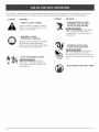
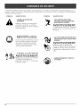
This operator's manuaHdescribes safety and internationaH symboHs and pictographs that may appear on this product,
Read the operator's manuaHfor compDte safety, assemMy, operating and maintenance and repair information,
SYMBOL MEANING
SYMBOL MEANING
• SAFETY ALERT SYMBOL
Indicates danger, warning or caution,
May be used in conjunction with other
symboHs or pictographs,
o WARNING - READ
OPERATOR'S MANUAL
• THROWN OBJECTS AND
ROTATING CUTTER CAN
CAUSE SEVERE INJURY
WARNmNG: Sma,objects
can be propelled at high speed,
causing injury, Keep away from the
rotating rotor,
@
@
Read the operator's manuaH(s)and follow
aHwarnings and safety instructions,
FaiHureto do so can resuHtin serious injury
to the operator and/or bystanders,
o KEEP BYSTANDERS AWAY
WARNING: Keepa,
bystanders, especially children and
pets, at least 50 feet (15 m) from the
operating area,
,, SPINNING ROTOR CAN
CAUSE SEVERE iNJURY
WARNmNG: Keephands,
feet, and clothing away from the
discharge area. Do not step in front of
the unit, or use hands to clean the rotor
area,
• KEEP HANDS AND FEET AWAY

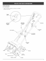
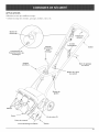
APPLiCATiONS
As a snow thrower:
• CHeats snow from wdkways, driveways, sidewalks,
pathways and more
Starter
Button
Bail
Overload
Protection
Switch
Discharge
Directional
Controm
Cord
Retainer
Cord Outlet
Receptacme
\
\
Cord Guide
Bar
Handmebar
Knob
Vanes
Wheels
Rotor
Belt Case Cover
Flange Lock Nut
Cover
Screws (7)
Scraper

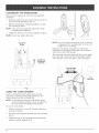
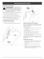
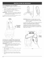
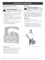
ASSEMBUNG THE HANDLEBARS
Before you can operate the unit, you must adjust the
handHebars.
1. When you unpack the unit, Hoosenthe two knobs on
the inside of the handHebars (Fig. 1).
2. With the unit upright, swing the handHebars up into
the operating position.
NOTE: Take care not to pinch the switch wires when
)ositioning the handHebars.
3. Tighten the knobs to secure the handHebars in pHace.
NOTE: Do not over-tighten the knobs.
Handmebar
Knobs
Swing Top
Handmebars
Upwards
Fig. 1
USING THE CORD RETAINER
Thereisan extensioncordretainertopreventthe
extensioncordfromdisconnectingduringuse.The
retainerhangs from thecordguidebar.
NOTE: Do not pHugtheextensioncord intothepower
sourcereceptacleuntiHthecordisconnectedto
thecord retainerand pHuggedintothe unit,
To use thecord retainer:
1. FoHdthe extension cord in half, forming a tight loop
near the receptacle.
2. Push the loop through the bottom hole in the retainer
(Fig, 2).
3. Slide the loop over the retaining clip and pull down
until the cord fits snugly (Fig. 2).
F_g. 2
NOTE: Use a UL-approved extension cord, A lO0-foot,
14-gauge cord is recommended. A 50-foot, 16-
gauge cord is acceptable.
Both the cord retainer and guide bar restrain the
extension cord and keep it out of the way at all times,
safely to the side of the operator.
The extension cord and retainer will slide on the guide
bar as the unit is moved to the left and right, Connect
your extension cord to the unit as shown in Figure 3.
/
Cord WIll Slide
Side to Side
F_g. s

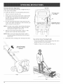
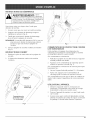
STARTING INSTRUCTIONS
WARNING: AvoidaccidentaH
starting. Make sure
you are in the starting position when using
the snow thrower. To avoid serious injury,
the operator and unit must be in a staMe
position while starting.
You must follow this sequence correctHy to start the unit.
1. Make sure you have pHugged in the unit.
2. Press in and hoHdthe red starter button (Fig. 4).
3. WhiHehoHding the starter button, lift and hoHdthe bail
NOTE: The unit will NOT start if you faiHto press and
hoHdthe starter button untiHyou Hiltthe bail
4. HoHdthe bail and begin operating the unit (Fig. 5).
STOPPING iNSTRUCTiONS
1. Release your hand from the bail.
2. The starter button will pop out and the unit will stop.
Overload
Protection
Switch
F_g. 4
OVERLOAD PROTECTION SWITCH
This unit is equipped with an ovedoad protection switch
to protect the circuit (that the unit is plugged into) from
short circuit overloads.
If the switch pops out:
1. Release the bail and allow the unit to stop and cool
for a minute.
2. Press the overload switch to reset. Resume
operation (Fig. 4).
If the switch pops again shortly after the first time:
1. Allow the unit to cool for 15 to 30 minutes.
2. After the unit has cooHed, press the ovedoad switch
to reset. Resume operation.
If the switch does not stay in, or if it continues to pop out
during operation, take the unit to an authorized service
dealer for repair.
OPERATmNG THE UNmT
1. Start the unit according to the Starting Instructions.
The depth and weight of the snow governs the
forward speed.
2. Push the unit so that it rides on the wheels and
scraper.
3. Make sure the power cord is attached to the cord
retainer and rests on the guide bar. The power cord
should trail to the side of the operator.

DischargeDirectionAdjustment
SnowmaybedischargedtotheHeft,straightforward,or
totherightoftheoperator,
Tochangethedirection,usethefoHo%nginstructions:
1, ReHeasethebaiHtostoptherotor,
2, FirmHygraspthedischargedirectionalcontroHhandHe
andpullitup.ThisreHeasesthespfing-badedrod
fromthedischargedirectionshotandallowsfree
movement(Fig.6)
3, TurnthedischargedirectionaHcontroHtotheHeft,the
centerortheright,dependingonwhichdirectionyou
wanttothrowthesnow(Fig.7),
NOTE:Fromthecenterposition,thedischargedirectionaH
controHturnsapproximateHy45degreesineither
direction(Heftorright),Donotforceit,
4, Releasethedischargedirectionalcontrolsoitfits
intotheslottosecurethedesiredposition,
NOTE:Makesurethedischargedirectionalcontrolis
securelypositionedindirectionslotandcannot
rotatefreely,
5, Restarttheunitaccordingtothe.Starting/nstructions+
Pull the Discharge
DirectionaB Contro_
Upwards
Top View
Discharge snow to
LEFT of operator
Discharge snow
in FRONT
Discharge snow to
RIGHT of operator
Rg. 7
Tips for Best Snow Throwing Results
• For the most efficient snow throwing, keep the vanes
parallel and throw snow downwind,
, Slightly overlap each swath you make (Fig. 8),
Fig. 6
Rg. 8
10

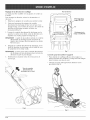
SERVmCmNG THE UNmT
Extreme care and knowbdge of the system is required
when servicing this unit. Service should be performed by
qualified service personnel only. Replacement parts for
this unit must be identical to the parts they replace. Refer
any repair to an authorized service deabr.
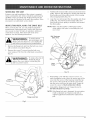
mNSPECTmNG/REPLACmNG THE DRmVE BELT
When servicing the unit, use only original equipment
manufacturer replacement parts, inspect the drive belt
once a year or every 50 hours of operation, whichever
comes first, for wear. if the drive belt needs to be
rephced, use the following instructions.
WARNING: Toavoidserious
personal injury, turn
off the unit and allow it to cool Unplug the
unit before you perform any maintenance.
1. Remove the flange lock nut from the belt case cover
with a wrench or nut driver (Fig. 9).
2. Remove the seven (7) screws from the belt case
cover using a #T20 Torx bit or fiat blade screwdriver
(Fig. 9).
WARNING: Toreducetheriskof
electricalshock,
replacethe cover beforeconnectingthe
unit to a power source.
3. Puii the belt tensioner (idler arm) away from the drive
pulley. Remove the damaged or broken belt from the
driven pulley and drive pulley inside of the housing.
Discard appropriately (Fig. 10).
4. Loop the new belt around the drive pulley and driven
pulley (Fig. 10). Puii the belt tensioner (idler arm)
away from the drive pulley to instaii the belt around
the drive pulley.
NOTE: Make sure the washer is stiii in place on the
driven pulley shaft prior to reinstalling the belt
case cover.
Belt Tensioner
(Idler Arm}
Drive Shaft
Belt
Fig. 10
Cover
Screws (7)
Flange Lock Nut
5. Reinstall the cover with the seven (7) screws. To
make installation easier, place the narrow part of the
cover into the recess of the housing. Install the top
two screws, then push the rest of the cover down
into the recess and over the rotor shaft. Torque all
seven (7) screws to 18-23 inolb (2.0-2.5 N,m)o
6. Reinstall the flange lock nut. Torque the nut to
80-100 inomb(9.0-11.2 N,m).
NOTE: if the flange lock nut is damaged, do not replace
it with a standard nut. Replace only with an
original equipment manufacturer replacement
part.
Fig. 9
11

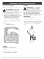
REPLACING THE SCRAPER
Use only original equipment manufacturer replacement
parts.
2.
WARNING: Toavoidserious
personal injury,
always turn your unit off and unplug it
before you perform maintenance.
Place the unit on the ground or on a work bench.
Position the unit so the vanes and rotor are facing up.
Beneath the rotor, locate the three (3) screws securing
the scraper to the housing. Remove them using a
#T20 Torx bit or fiat blade screwdriver (Fig. 11).
3. Remove the scraper and discard it appropriately.
4. The new scraper wiii snap into place. Once in place,
attach it to the unit by reinstalling the three (3)
screws.
Torque the screws to:
25-30 inoib (2.84.3 Nora).
before you clean or service it.
Use a small brush to clean off the outside of the unit. Do
not use strong detergents. Household cleaners that
contain aromatic oils such as pine and lemon, and
solvents such as kerosene, can damage plastic housing
or handle. Wipe off any moisture with a soft cloth.
TRANSPORTING
, Secure the unit while transporting.
To move the unit, grasp it by the top and middle front
handles (Fig. 12).
if you are transporting the unit with the handles folded,
be careful not to make contact and accidentally bend
the discharge directional control (Fig. 6). if you bend or
damage the control, you can no longer adjust the
vanes.
Scraper
Fig. 11
STORAGE
• Allow the motor to coon before storing.
• Store the unit bcked up to prevent unauthorized use
or damage.
• Store the unit in a dry, well-ventilated area.
• Store the unit out of the reach of children.
Fig. 12
12

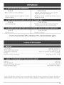
CAUSE
Unit is unpHugged
Starter button or baiHwere improperly used
OveHoad protection switch has popped out
CAUSE
BeHtis damaged
CAUSE
Scraper is worn
ACTION
Check cordtomake sureitispHuggedintoan eHectdcaHoutHet
Press in starter button, hold it, and hold baiH
Push it in and follow the Starting Instructions
ACTION
RepHacethe beHt,according to Inspecting/Replacing the
Driver Belt
ACTION
RepHacethe scraper
Jf further assistance is required, contact your authorized service deaJer
Motor type ......................................................................................................................................... A.C,, 120 VoHtsEHectric
Operating RPM ......................................................................................................................................... up to 14,000 rpm
Ignition Switch ................................................................................................................................. Bail Lock Safety Button
Amperage ............................................................................................................................................................... 8,5 amps
OveHoad Protection .......................................................................................................................... 120V, 15 amp Breaker
HandHes ............................................................................................................................................................... SteeHTube
Approximate Unit Weight ............................................................................................................................... 20 Ibs, (9 kg,)
Snow Depth (maximum) .................................................................................................................. 6 inches (0.152 meters)
Cleared Path Width ..................................................................................................................... 12,5 inches (0,318 meters)
_AIIspecifications are based on the latest product information available at the time of printing. We reserve the right to
make changes at any time without notice,
13

MANUFACTURER'S LIMITED WARRANTY FOR:
The limited warranty set forth below is given by MTD
LLC ("MTD"} with respect to new merchandise purchased and
used in the United States, its possessions and territories.
MTD warrants this product against defects in material and
workmanship for a period of two (2) years commencing on the
date of original purchase and will, at its option, repair or
replace, free of charge, any' part found to be defective in
material or workmanship. This limited warranty' shall only apply
if this product has been operated and maintained in
accordance with the Operator's Manual furnished with the
product, and has not been subject to misuse, abuse,
commercial use, neglect, accident, improper maintenance,
alteration, vandalism, theft, fire, water or damage because of
other peril or natural disaster. Damage resulting from the
installation or use of any accessory or attachment not
approved by MTD for use with the product(s) covered by this
manual will void }tour warranty as to any' resulting damage. This
warranty is limited to ninety (90} days from the date of original
retail purchase for any' MTD product that is used for rental or
commercial purposes, or any other income-producing purpose.
HOW TO OBTAIN SERVICE: Warranty, service is available,
WITH PROOF OF PURCHASE THROUGH YOUR LOCAL
AUTHORIZED SERVICE DEALER. To locate the dealer in your
area, please check ff)r a listing in the Yellow Pages or contact
the Customer Service Department of MTD LLC by calling
1-800-345-8746 or writing to P.O. Box 361131, Cleveland OH
44136-0019 or if in Canada call 1-800-668-1238. No product
returned directly to the factory will be accepted unless prior
written permission has been extended by the Customer
Service Department of MTD LLC.
This limited warranty does not provide coverage in the
following cases:
A. Tune-ups - Spark Plugs, Carburetor Adjustments, Filters.
B. Wear items - Bump Knobs, Outer Spools, Cutting Line,
Inner Reels, Starter Pulley, Starter Ropes, Drive Belts.
C.
MTD does not extend any warranty for products sold or
exported outside of the United States of America, its
possessions and territories, except those sold through
MTD's authorized channels of export distribution.
MTD reserves the right to change or improve the design of
any' MTD Product without assuming any' obligation to modify
any product previously manufactured.
No implied warranty, including any implied warranty of
merchantability or fitness for a particular purpose,
applies after the applicable period of express written
warranty above as to the parts as identified. No other
express warranty or guaranty, whether written or oral,
except as mentioned above, given by any person or
entity, including a dealer or retailer, with respect to any
product shall bind MTD. During the period of the
Warranty, the exclusive remedy is repair or replacement
of the product as set forth above. (Some states do not
allow limitations on how long an implied warranty lasts, so
the above limitation may not apply to you.)
The provisions as set forth in this Warranty provide the
sole and exclusive remedy arising from the sales. [VITD
shall not be liable for incidental or consequential loss or
damages including, without limitation, expenses incurred
for substitute or replacement lawn care services, for
transportation or for related expenses, or for rental
expenses to temporarily replace a warranted product.
(Some states do not allow limitations on how long an implied
warranty lasts, so the above limitation may not apply to you.)
In no event shall recovery of any kind be greater than the
amount of the purchase price of the product sold. Alteration
of the safety' features of the product shall void this Warranty.
You assume the risk and liability for loss, damage, or injury
to you and your property and/or to others and their property'
arising out of the use or misuse or inability to use the
product.
This limited warranty shall not extend to anyone other than
the original purchaser, original lessee or the person for whom
it was purchased as a gift.
How State Law Relates to this Warranty: This warranty
gives you specific legal rights, and you may also have other
rights which vary from state to state.
To locate ],'our nearest service dealer dial 1-800-345-8746
in the United States or 1-800-668-1238 in Canada.
MT[) LLC
P.O. Box 361131
Cleveland, OH 44136-0019
14
Page is loading ...
Page is loading ...
Page is loading ...
Page is loading ...
Page is loading ...
Page is loading ...
Page is loading ...
Page is loading ...
Page is loading ...
Page is loading ...
Page is loading ...
Page is loading ...
Page is loading ...
Page is loading ...
Page is loading ...

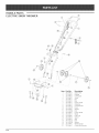
HANDLE PARTS
ELECTRIC SNOW THROWER
i
Item Part No, Description
1 753-04427 Switch Asm
2 753-04428 Bushing
3 753-04429 (;able guide
4 753-04430 Screw
5 753-04431 Nut
6 753-04432 Bail
7 753-04433 Upper Handle
8 753-04434 Guide Bar
9 753-04435 Cord Restraint
10 791-182677 Knob
11 753-04052 Washer
12 791-182899 Bolt
13 753-04436 Lower Handle
14 753-04437 Wheel
15 753-04062 Push Cap
16 753-04438 Spacer
17 753-04439 Axel
18 791-182213 Bolt
19 791-182678 Washer
20 753-04440 Wheel Bracket
21 753-04441 Control Rod Bracket
F16

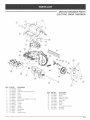
MOTOR/THROWER PARTS
ELECTRIC SNOW THROWER
item Part No. Description
1 791-181345 Screw
2 791-182409 Washer
3 791-000012 Vane Control Handle (includes 4)
4 791-000001 Grip
5 753-04416 (:over
6 753-04079 Washer
7 791-000002 Spring
8 753-04421 Motor Assm w/Baffle, Fan & Pulley
9 753-04422 Motor Strap
10 791-181862 Screw
11 791-00010 Scraper
12 791-181858 Screw
13 791-00015 Spring
14 791-00016 Idler Arm
15 753-04081 Ball Bearing
16 791-00017 Keeper
17 753-04082 Flange Bearing
item Part No.
18 791-00018
19 753-04080
20 753-04443
21 753-04056
22 791-00022
23 753-04423
24 791-182910
25 791-00020
26 753-04425
27 791-00013
28 791-00014
Description
Driven Pulley
Washer
Belt Case Cover
Flange Lock Nut
Axle Auger
Auger
Washer
Vane
Snow Thrower Housing
Push Nut
Drive Belt
F17
Page is loading ...
-
 1
1
-
 2
2
-
 3
3
-
 4
4
-
 5
5
-
 6
6
-
 7
7
-
 8
8
-
 9
9
-
 10
10
-
 11
11
-
 12
12
-
 13
13
-
 14
14
-
 15
15
-
 16
16
-
 17
17
-
 18
18
-
 19
19
-
 20
20
-
 21
21
-
 22
22
-
 23
23
-
 24
24
-
 25
25
-
 26
26
-
 27
27
-
 28
28
-
 29
29
-
 30
30
-
 31
31
-
 32
32


Yard Machines 31A-040-701 Owner's manual
- Type
- Owner's manual
- This manual is also suitable for
Ask a question and I''ll find the answer in the document
Finding information in a document is now easier with AI
in other languages
Related papers
Other documents
-
Yard-Man 769-03412 User manual
-
-
Craftsman 31C-040-701 Owner's manual
-
MTD Yard Machines 31A-020-900 Owner's manual
-
-
-
-
-
-
Chicago Electric 68010 Operating And Service Instructions