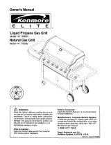
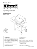
Kenmore 141.156400 Owner's manual
- Category
- Barbecues & grills
- Type
- Owner's manual
This manual is also suitable for

Owner'sManual
E L I T E
LiquidPropaneGasGrill
Model141.156400
®
Z_ WARNING:
Readthis Owner'sManual carefully and besure your
gas grillispropedy assembled, installed and main-
tained. Failure to follow these instructions could
resultin sedous bodily injuryand/or propertydam-
age. This gas gdll isintencJedfor outdoor use only
and is not intended to be installed in or on
recreational vehicles or boats.
Note to Installer:
Leave this Owner's Manual with theconsumer
afterdelivery and/or installation.
Note to Consumer:
Leavethis Owner's Manual in a convenient place
for futurereference.
Manufacturer's Customer Service Helpline:
If there are damaged or missing parts when you
unpackthis unitfrom the shipping box, or you have
questions about assembly, call us 8am - 8pm CST,
Mondaythrough Fdday at:
1-888-317-7642
Sears, Roebuck and Co.,
Hoffman Estates, IL60179 U.S.A.
P4795A - Date:l 1/21/00

Warranty ..................................................... 2
Safety Instructions .................................... 2
Pre-Assembly Instructions ......................... 4
Hardware, Parts Diagram and Lists ..... 5
Assembly Instructions ................................. 8
lighting Instructions .................................. 13
Cleaning and Maintenance Instructions .... 15
Frequently Asked Questions .................. 17
Cooking Instructions ................................ 18
Cooking Guide and Recipes ................ 24
Full l-Year Warranty on Grill
For one year from the date of purchase Sears will
repair or replace, at our option, any grill part
(except for paint loss and ignitor battery) that is
defective in material or workmanship.
Limited Warranty on Selected Grill Parts
From one year after the date of purchase for the
designated time periods listed below, Sears will
replace the following gdll parts if they are defective
in material or workmanship. You will be charged
for labor.
• Lifetime of Grill: Exterior Stainless Steel Parts,
Aluminum Castings (except for paint loss)
• 2 Years: Flame Tamers, Cooking Gnds, Burners
• 4 Years: All Other Grill Parts (except ignitor battery)
Warranty Service
Warranty service is available by contacting your
nearest Sears Service Center.
Warranty Restrictions
• This warranty is void if grill is used for commer-
cial or rental purposes.
• This warranty applies only when the grill is
used in the United States.
• This warranty gives you specific legal dghts,
and you may also have other rights which vary
from state to state.
Sears, Roebuck and Co., Dept. 817WA,
Hoffman Estates, IL 60179
Z_WARNING
Combustion by-products produced when
using this product contain chemicals known
to the State of California to cause cancer,
birth defects, or other reproductive harm.
Z_WARNING
Failure to comply with these instructions
could result in a fire or explosion that
could cause serious bodily injury, death,
or property damage.
Grill Installation Codes
This gas grill must be installed in accordance with
all local codes. In areas without local codes,
follow the latest edition of the National Fuel Gas
Code ANSI Z223.1. In Canada, installation must
conform to standard CAN/CGA lb149.1 or 1-
b149.2 (Installation Code for Gas Burning Appli-
ances and Equipment) and all local codes.
Correct LP Gas Tank Use
LP gas gnll models are designed for use with a
standard 20 lb. Liquid Propane Gas (LP gas)
tank; not included with gdll box.. Never connect
your gas gdll to an LP gas.tank that exceeds
this capacity: A tank of approximately 12 inches
in diameter by 18-1/2 inches high is the maxi-
mum size LP gas tank to use. We recommend
buying an "OPD" gas tank which offers an Overfill
Prevention Device. This safety feature prevents the
tank from being overfilled which can cause mal-
function of the LP gas tank, regulator and/or gdll.
The LP gas tank must be constructed and
marked in accordance with specifications of the
U.S. Dept. of Transportation (DOT). In Canada, the
LP gas tank must meet the Canadian Transpoda-
tion and Communications (CTC)
specifications. Also be sure:
1. The LP gas tank has a shutoff valve, termi-
nating in an LP gas supply tank valve outlet,
that is compatible with a Type 1 tank con-
nection device. The LP gas tank must also
have a safety relief device that has a direct
communication with the vapor space of the
tank.
2. The tank supply system must be arranged for
vapor withdrawal.
3. The LP gas tank used must have a collar
to protect the tank valve.
2 Sears, Roebuck and Co.

ProperPlacementand Clearanceof Grill
Neveruseyourgasgrillinagarage,porch,shed,
breezewayoranyotherenclosedarea.Yourgasgrillis
tobeusedoutdoorsonly,atleast24inchesfromthe
backandsideof anycombustiblesurface.Your
gas grillshould not be placed under any surface
that will bum. Do not obstruct the flow of ventilation
air around the gas grill housing.
This outdoor gas grill isnot intended to be installed in
or on recreational vehicles and/or boats.
WARNING
Failure to comply with these instructions
could result in a fire or explosion that
could cause serious bodily injury, death,
or property damage.
• Never connect an unregulated LP gas tank to
your gas grill. The gas regulator assembly
supplied with your gas grill is adjusted to have
an outlet pressure of 11" water column (W.C.)
for connection to an LP gas tank.
• Only use the regulator and hose assembly
supplied with your gas grill. Replacement
regulators and hose assemblies must be those
specified by Sears.
• Have your LP gas tank filled by a reputable
propane gas dealer and visually inspected and
re-qualified at each filling.
• Never fill the gas tank beyond 80% full.
Have your propane gas dealer check the
release valve after every filling to ensure that it
remains free of defects.
• Always keep LP gas tanks in an upright
position.
• Do not store (or use) gasoline orother flammable
vapors and liquids in the vicinity of this gas grill.
• An LP gas tank that is not connected for use must
not be stored in the vicinity of this or any other gas
grill.
• Do not subject the LP gas tank to excessive heat.
• Never store an LP gas tank indoors. If you
store your gas gdll in the garage or other indoor
location, always disconnect the LP gas tank
first and store it safely outside.
• LP gas tanks must be stored outdoors in a
well-ventilated area. Disconnected LP gas tanks
must not be stored in a building, garage or
any other enclosed area.
• When your gas grill is not in use the gas
must be turned off at the LP gas tank.
• The regulator and hose assembly must be
inspected before each use of the grill. If there
is excessive abrasion or wear or if the hose is
cut, it must be replaced prior to the grill being
used again.
• Keep the gas regulator hose away from
hot grill surfaces and dripping grease.
Avoid unnecessary twisting of hose. Visually
inspect hose prior to each use for cuts,
cracks, excessive wear or other damage.
If the hose appears damaged do not use the
gas grill. Call Sears at 1-8O0-4-MY-HOME for
a Sears authorized replacement hose.
• Never light your gas grill with the lid closed
or before checking to insure the burner tubes
are fully seated over the gas valve orifices.
• Never allow children to operate your gdll. Do
not allow children to play near your grill
AkWARNING
A strong gas smell, or the hissing sound of
gas indicates a serious problem with your
gas grill or the LP gas tank. Failure to
immediately follow the steps listed below
could result in a fire or explosion that could
cause serious bodily injury, death, or prop-
erty damage.
• Shut off gas supply to the gas grill.
• Turn the control knobs to OFF position.
• Put out any flame with a fire extinguisher.
• Open grill lid.
• Get away from the LP gas tank.
• Do not try to fix the problem yourself.
• If odor continues or you have a fire you
cannot extinquish, call your fire department.
Do not call near the LP gas tank because
your telephone is an electrical device and
could create a spark resulting in fire and/or
explosion.
3
CAUTION: Spiders and small insects occa-
sionally spin webs or make nests in the
grill burner tubes during transit and ware-
housing. These webs can lead to a gas flow
obstruction which could result in a fire in
and around the burner tubes, This type of
fire is known as a "FLASH-BACK" and can
cause serious damage to your grill and
create an unsafe operating condition for the
user.
Although an obstructed burner tube is not
the only cause of "FLASH-BACK", it is the
most common cause.
To reduce the chance of "FLASH-BACK",
you must clean the burner tubes before
assembling your gdll, and at least once a
month in late summer or early fall when
spiders are most active. Also perform this
burner tube cleaning procedure if your grill
has not been used for an extended period
of time.

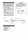
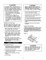
To reduce the chance of "FLASH-BACK" (see
CAUTION on page 3) clean the burner tubes and
burners before fully assembling your gdll. Remove
the cotter pin from the rear underside of each
burner using a pair of long nose pliers. Carefully
lift each burner up and away from the gas valve
odfice, then refer to Figure 1 and perform one of
these three cleaning methods:
1. Bend a stiff wire, (a lightweight coat hanger
works well) into a small hook as shown below.
Run the hook through the burner tube and
inside the burner several times to remove any
debds.
{ '1)
2. Use a bottle brush with a flexible handle. Run
the brush through the burner tube and inside
the burner several times, removing any debris.
3. Use an air hose to force air through each
burner tube. The forced air should pass debris
or obstructions through the burner and out the
pods.
Z WARNING
The location of the burner tube with respect
to the orifice is vital for safe operation.
Check to ensure the edfice is inside of the
burner tube before using your gas gdll. See
Fig. 2. If the burner tube does not fit over
the valve Ddfice, lighting the burner may
cause explosion and/or fire.
Figure 2
GAS VALVE ASSEMBLY
ORIFICE
BURNER TUBE
Figure 1
TO CLEAN BURNER TUBE,
INSERT HOOK HERE
SPARK ELECTRODE
ASSEMBLY
/
BURNER TUBE
GAS COLLECTOR BOX
¢o.......i? ;iiooi ;iio oll
COTTER PIN
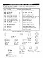
• Size 2 phillips screwdriver
• Size 4 phillips screwdriver
• Adjustable wrench
• Long nose pliers
• Open-end wrench, 11116" size
• Protective work gloves
• Eye protection
4

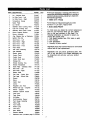
The following table illustrates a breakdown of the hardware pack. It highlights what components are used
in the various stages of assembly.
Ref.
HO05
H001
H002
H003
H005
H005
H005
H005
H012
H009
H004
H015
H008
H013
H014
P8080A
Component Qty. to
1/4"x1/2" Phillips Head Screw 4
3/8" Wheel Bolt 2
Spdng Washer 2
3/8" Nut 2
1/4"x1/2" Phillips Head Screw 8
1/4"x1/2" Phillips Head Screw 4
114"x112"Phillips Head Screw 2
1/4"x1/2" Phillips Head Screw 2
1/4"xl-3/8" Phillips Head Screw 4
1/4" Lock Nut 4
1/4"x3/4" Phillips Head Screw 8
M6 Phillips Head Screw 2
M6 Nut 2
M18xl.5 Nut 1
M8x1.25 Nut 1
AA Battery 1
Use
Purpose of Components
Install Bottom Shelf To Cart Legs
Install Wheels To Cart Legs
Install The Two Braces To Cart
Restdct Drawer From Being Pulled Out Too Far
Install Pressure Cylinder Holder To Cart
Install Tank Guide To Cart
Install Grill Head To Cart
Install Side Shelves To Cart
Install Tool Holder To Side Shelf
Install Pressure Cylinder To Holder
Install Tank Hook To Pressure Cylinder
Install To Electric Ignitor
Actual Size and Quantity of Each Hardware Piece:
3/8" Wheel Bolt
Qty. 2
Ref. # HO01
©
SpringWasher
Qty. 2
Ref. # HO02
1/4"x3/4" Phillips
Head Screw
Qty. 8
Ref, # HO04
1/4"xli'Z' Phillips
Head Screw
Qty. 20
Ref. # H005
AA Battery
Qty. 1
Part # P8080A
M6 Phillips Head Screw
Qty. 2
Ref. # HO15(packed w_th Tool Holder)
1/4"xl-3/8" Phillips Head Screw
Qty. 4
Ref, # H012
M18x1+5 Nut Qty. 1
Ref+ #
HO13(attached to
Pressure Cylinder)
©
MSx1.25 Nut Qty. 1
Ref. # HO14(attached
to Pressure cylinder)
©
3/8" Nut
Qty.2
Ref. # H003
©
114" Lock Nut
Qty. 4
Ref. # H009
©
M6 Nut
Qty. 2
Ref, # HOOS(packed
with Tool Holder)

Remove all components from the packing carton and place within easy reach. Do not throw the shipping carton
away; instead use it as an elevated assembly surface.
45 _" 3
51
16
47
3O
6

REF# DESCRIPTION PART# QTY
1. Lid - Stainless Steel P0149F 1
2. Lid Side Panel - Left P0145B 1
3. Lid Side Panel - Right P0144B 1
4. Temperature Gauge P0615D 1
5. Name Plate P0459A 1
6. Ud Handle P0237D 1
7. Stainless Steel Cooking Rack P1521B 1
8. Cast Iron Cooking Grid P1648B 2
9. Stainless Steel Flame Tamer P1733A 2
10. Burner Support Bracket P2218B 1
11. Burner Assembly P1935A 4
12. Gas Collector Box w/ Electrode P2618A 2
13. Ignition Wire Set P2622A 1
14. Bowl Panel - Left PO751A 1
15. Bowl Panel - Right P0752A 1
16. Bowl Panel - Rear PO732B 1
17. Bowl Panel - Front PO731B 1
18. Heat Shield P2968A 1
19. Gas Valve Assembly P32ClA 4
20. Gas Manifold P5028A 1
21. Electric Ignitor P'2503D 1
22. Control Panel P2957A 1
23. Control Knob P343OA 4
24. Control Knob Seat P3430C 4
25. Storage Bin P1134A 2
26. Grease Draining Tray P2736A 1
27. Grease Receptacle P2717C 1
28. Insert Plate - Stainless Steel P1131B 2
29. Side Shelf- Left Pl131E 1
30. Side Shelf- Right Pl132C 1
31. Bottom Shelf P1048B 1
32. Cart Legs - Castor Side P0937A 1
33. Cart Legs - Wheel Side P0840A 1
34. Drawer P8078B 1
35. Brace P4213A 2
36. Castor Seat P4521A 2
37. Castor P5109A 2
38. Regulator and Hose P3632E 1
39. Wheel Hub Cap - Graphite P5113C 2
40. Wheel - Graphite P5106D 2
41. Pressure Cylinder Holder P4033C 1
42. Tank Hook P4033A 1
43. Tank Guide P4033B !
44. AA Battery P808OA 1
45. Heat-Insulating Spacer P5573A 2
46. Fuel Gauge Assembly P80FgB 1
47. Fixing Ring P80F9C 1
48. Tool Holder P55B6B 1
49. Screw Cover P55B6C 2
50. Tool Hook P55B6D 5
51. Rain Shield P80D5A 4
-- Owner's Manual P4795A 1
-- Hardware Pack (contents page 5)P55D9A 1
If there are damaged or missing parts when you
unpackthis unit fmmthe shipping box, oryou have
questions about assembly, call us 8am- 8pm CST,
Mondaythmugh Fdday
1-888-317-7642
For the repair or replacement parts you need:
Call 6 am - 11 pm CST, 7 days a week
1-800-366-PART
To make sure you obtain the correct replacement
parts for your Kenmore Elite gas grill, please
refer to the part numbers on this page. The
following information is required to assure you
receive the correct parts:
1. Grill Model Number (see CSA label on gdll)
2. Part Number
3. Part Description
4. Quantity of parts needed
Important: Keep this Owner's Manual for convenient
referral and .for part replacement.
Important: Use only Sears authorized parts. The
use of any part that is not Sears authorized can
be dangerous and will also void your product
warranty.
7

Before assembling your gas gdll, use the parts
list to check that all necessary parts have been
included. Inspect gnll and cart parts for damage
as you proceed. Do not assemble or operate your
grill if it appears damaged. If you have questions
during the assembly process, call 8am - 8pro
CST, Monday through Friday,
1-888-317-7642
Remove the white PVC protective film from
stainless steel surfaces before assembly.
CAUTION:
While it is possible for one person to assemble
this gas gdll, obtain assistance from another
person when handling some of the larger, heavier
pieces, especially the grill head.
Remove all cart pads, hardware, and gdll head
from carton. Assemble the gas grill on a protective
work surface, such as the shipping box, to avoid
scratching grilt surfaces. Refer to parts list and
hardware pack illustrations to help you assemble
your grill.
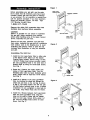
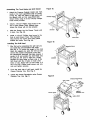
Assembling The Grill Cart
1. Install the Cart Legs-Castor Side to either side
of the Bottom Shelf. Make sure the Drawer
Channel faces inwards. Secure using 2 of the
114"x112" Phillips head screws provided. Install
the Cart Legs-Wheel Side to the other side of
Bottom Shelf by using the same-sized screws.
See Fig. 1.
2. Screw the 2 Castors into Castor Seats (see
bottom of Cart Legs-Castor Side). Tum the
threaded castor stem by hand, clockwise until it
stops. Tighten with an Open-end 11/16" wrench.
See Fig. 2.
3. Install the 2 Wheels to the Cart Legs-Wheel
Side, by inserting the wheel bolt through the
wheel and axle hole on the cart leg as shown
in Fig. 2. Put spring washer and 3/8" nut onto
bolt and tighten securely using a size 4 phillips
screwdriver. Do not overtighten or wheel will not
turn freely. Snap Wheel Hubs onto the wheels.
4. Install the 2 Braces between Cart Legs-Castor
Side and Cart Legs-Wheel Side. Align the
holes on the ends of Brace with the tapped
holes on Cart Legs. Secure firmly using 4 of
the 1/4"xl/2" Phillips head screws for each
Brace. See Fig. 3.
Figure 1
CART LEGS-
CASTOR SIDE
ORAWER CHANNEL
CASTOR
SEAT
BOTTOM SHELF
CART LEGS-
WHEEL SIDE
Figure 2
CASTOR
SEAT
I
CASTOR
HUB
Figure 3
BRACE
BRACE
8

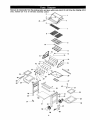
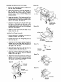
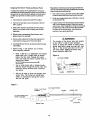
AssemblingTheTankGuideand Grill Drawer
,
Attach the Pressure Cylinder Holder and Tank
Guide to the Cart Legs-Wheel Side as shown
in Fig. 4a. Align the holes of both parts with
the tapped holes on Cart Legs-Wheel Side.
Secure firmly using 4 of the 1/4"x112" Phillips
head screws provided.
2. Install a 1/4"x1/2" Phillips head screw to the
rear of each Drawer Track. Without these
screws the drawer will not stop propedy.
3. Slide the Drawer into the Drawer Tracks until
it stops. See Fig. 4b.
4,
Install a 1/4"x112" Phillips head screw to the
front of each Drawer Track. This important
step prevents the drawer from being pulled
outside the tracks. See Fig. 4b.
installing The Grill Head
.
Now that you've assembled the grill cart you
can install the pre-assembled Gdll Head.
See Fig. 5. To reduce the weight of the Gdll
Head, we suggest you open the Gdll Lid and
remove the packed components. Even with
the components removed, this step requires 2
people to lift and position the Gdll Head onto
the griU cart. Be sure to align the 2 holes
beneath the hang ledge on each side of the
Gdll Head with the 2 holes on each cross
brace of cart. Raise Gdll Lid and insert 4 of
the 1/4"xl-3/8" Phillips head screws and lock
nuts and tighten securely.
2. From the back side of grill head, install the
Grease Draining Tray. See Fig. 5.
3. Center the Grease Receptacle under Grease
Draining Tray. See Fig. 5.
Figure 4a
DRAWER TRACK
DRAWER
PRESSURE
CYLINDER
HOLDER
TANK GUIDE
Figure 4b
J
DRAWER
Figure 5
CROSS BRACE
GREASE RECEPTACLE
GRILL HEAD
i
/
//
GREASE
DRAINING TRAY
HANG LEDGE

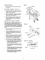
Installing Side Shelves and Tool Holder
1. Remove and discard the protective rubber boots
from the Side Shelf braces,
Figure 6a
2,
Attach Side Shelves to Cart Legs as shown in
Fig. 6a. Align the 4 holes on each Side Shelf
frame with the holes on the Cart Legs. Tighten
securely using 4 of the 1/4"x3/4" Phillips head
screws provided.
SIDE SHELF
SIDE SHELF
3.
Install and slide the 5 Tool Hooks onto the Tool
Holder from the narrow section. For safety's sake,
the Tool Hooks face in the same direction as both
ends of Tool Holder. See Fig. 6b.
4.
Attach the Tool Holder to the left Side Shelf. Align
the holes on Tool Holder with the holes on the
left side of Side Shelf. Secure firmly using 2 of
the M6 Phillips head screws and M6 nuts packed
with the Tool Holder.
5. Slide the 2 screw covers onto both ends of Tool
Holder. See Fig. 6b.
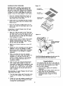
Installing Fuel Gauge Assembly
1. Unscrew the M18x1.5 and M8x1.25 nuts from the
Pressure Cylinder. See Fig. 7a.
2. Unscrew and remove the Fixing Ring from the
Dial. See Fig. 7a.
.
Insert the end with Pressure Cylinder through the
notched hole on right Side Shelf. See Fig. 7b.
Turn the Dial until it matches the notched hole,
and push it into the hole.
NOTCHED HOLE
FOR THE DIAL OF
FUEL GAUGE
Figure 6b
TOOL HOLDER
NARROW SECTION
Figure 7a
4.
5.
6.
Screw the Fixing Ring back to the Dial from the
Pressure Cylinder side. See Fig. 7c,
Insert the Pressure Cylinder into Pressure Cyl-
inder Holder, and secure using the detached
M18xl.5 nut. See Fig. 8.
Attach Tank Hook to the lower thread of Pressure
Cylinder, and secure firmly using the detached
M8x1.25 nut. Once tank is connected, the dial
will indicate amount of gas in tank.
Figure 8
CYLINDER
• ._J
_ANK HCOK
TANK GUIDE
PRESSURE
Figure 7b
DIAL
Figure 7c
FIXING RING
HOLE
PRESSURE
CYLINDER
DiAL
PRESSURE
10 CYLINDER
FIXING RING

Installing Storage Bins Figure 9
1. Place a Storage Bin into each Side Shelf,
See Fig. 9.
Ignitor Battery Installation - See Fig. t0
1.
2.
3.
Unscrew the Ignitor Cap located on the grill
Control Panel and remove the Contact and
Spring from the Ignitor Slot.
Place the manufacturer supplied AA battery
into the Ignitor Slot. Be sure to place the
positive pole facing toward you.
Place the Spring over the AA battery, then
place the Contact on top of the Spring.
Screw the Ignitor Cap back onto the grill
Control Panel.
Electrode Check - Requires an Assistant
Before placing the cooking components into your
gdU, ensure that the Spark Electrode Tip is
propedy positioned within each Gas Collector Box
(a 3-1/4" wide stainless mechanism found at the
front between each set of bumers.) The easiest way
to ensure this is to perform the following Electrode
Check:
1. Be sure all Control Knobs are set to OFF.
Open the Gdll Lid.
2.
Have an assistant stand behind to the dght
of the gdll and look down at each Gas
Collector Box. NEVER put your face inside
the Gdll Head.
3,
,
Press the Ignitor Cap and have the assistant
watch for a small blue spark within each
Gas Collector Box. If a spark is present the
Electrode Tips are propedy positioned.
If no spark is seen the Spark Gap shown in
Fig. 11 needs to be adjusted as follows:
• Using an adjustable wrench, loosen the Inside
Nut just until the Gas Collector Box can be
maneuvered andtumed upward.
• The gap between the Spark Electrode Tip
and the Spark Receiver should be approxi-
mately 3/16".
• Ifthe gap iswider than 3/16" use a pair of long
nose pliers and gently squeeze the Gas Collec-
tor Box until the gap is correct.
• Return the Gas Collector Box to its original
hodzontal position, secure the Inside Nut and
try the Electrode Check again.
STORAGE BIN
Figure 10
/GNITOR SLOT
IGNITOR CAP
AABATTERY
SPRING _
CONTACT
Figure 11 - Side View
GAS COLLECTOR BOX
SPARK ELECTRODE TIP
SPARK
SPARK RECEIVER
11

Installing Cooking Components
Important: Before cooking on your gdll the first
time, wash the cooking grids and warming rack
with warm, soapy water. Rinse and dry thoroughly.
Season with cooking oil regularly. After cooking is
completed, turn grill to HIGH setting for about five
minutes to bum off excess grease or food residue.
Figure t2
SECONDARY
COOKING RACK
CASTIRON
COOKING GRID
1. Place the 2 Stainless Steel Flame Tamers on
the lower ledge above burners. See Fig. 12.
They should meet in the center.
2. Evenly space the reversible Cast Iron Cooking
Gdds on the ledge above the Stainless Steel
Flame Tamers.
3. Place the Secondary Cooking Rack into the
slots on the upper left and upper right of grill
bowl panels.
Connecting A Liquid Propane Gas (LP gas)
Tank To Your Grill
1. Hang your filled gas tank on the Tank Hook.
The lower section of the gas tank will lean on
the Tank Guide. See Fig. 13. Make sure the
LP gas tank valve is in the full OFF position.
(Turn clockwise to close.)
2. Check the tank valve to ensure it has proper
external mating threads to fit the hose &
regulator assembly provided. (Type 1 connec-
tion per ANSI Z21.58a-1998)
3. Make sure all burner valves are in the OFF
position.
4. Inspect the valve connection port and regulator
assembly. Look for any damage or debris,
Remove any debris. Inspect hose for damage.
Never attempt to use damaged or plugged
equipment.
5. When connecting the hose and regulator
assembly to the tank valve, hand tighten nut
clockwise to a full stop. Do Not use a
wrench to tighten because it could damage
the Quick Coupling Nut and result in a
hazardous condition.
6. Open the tank valve fully (counterclockwise).
Use a soapy water solution to check all
connections for leaks before attempting to light
your gdll. See "Checking for LP Gas Leaks"
on page 13. If a leak is found, turn the tank
valve off and do not use your gdll until the
leak is repaired.
Disconnecting A Liquid Propane Gas (LP gas)
Tank From Your Grill
1.
2.
Turn the burner valves and LP gas tank valve
to the full OFF position. (rum clockwise to
close.)
Detach the hose and regulator assembly from
the LP gas tank valve by turning the Quick
Coupling Nut counterclockwise.
12
STAINLESS STEEL
FLAME TAMER
Figure 13
_TANK HOOK
ALREADY CONNECTED
rilE INLET OF GAS
MANIFOLD
TANK GUIDE
QUICK COUPLING
NUT
CAUTION: When the appliance is not in use, the
gas must be turned offat the supply tank.
Congratulations
Your Kenmore Elite gas gdll is now ready for
use. Before the first use and at the beginning
of each season (and whenever the LP gas
tank has been changed):
1. Read all safety, lighting and operating
instructions.
2. Check gas valve orifices, burner tubes and
burner ports for any obstructions.
3. Perform gas leak check according to
instructions found on page 13 of this
manual.

AWARNING
A strong gas smell, or the hissing sound of
gas indicates a serious problem with your gas
gdll or the LP gas tank. Failure to immedi-
ately follow the steps listed below could result
in a fire or explosion that could cause sedous
bodily injury, death, or property damage.
Shut off gas supply to the gas grill.
Turn the control knobs to OFF position.
Put out any flame with a fire extinguisher.
Open gdll lid.
Get away from the LP gas tank.
Do not try to fix the problem yourself.
If odor continues or you have a fire you
cannot extinquish, call your fire department.
Do not call near the LP gas tank because
your telephone is an electrical device and
could create a spark resulting in fire and/or
explosion.
Checking For LP Gas Leaks
Never test for leaks with a flame. Prior to first
use, at the beginning of each season, or every
time your LP gas tank is changed, you must
check for gas leaks. Follow these four steps:
1. Make a soap solution by mixing one part
liquid detergent and one part water.
2, Turn the grill control knobs to the full OFF
position, then turn the gas ON at source.
3. Apply the soap solution to all gas connec-
tions. If bubbles appear in the soap solution
the connections are not properly sealed.
Check each fitting and tighten or repair as
necessary.
4. If you have a gas leak that you cannot
repair, turn off the gas at the source, discon-
nect fuel line from your gdll and cell
1-800-4-MY-HOME or your gas supplier for
repair assistance.
/ WARNING
Failure to open the grill lid during the
lighting procedures could result in a fire
or explosion that could cause serious
bodily injury, death, or property damage.
6. Set control knobs to OFF and open the LP gas
tank valve slowly until 1/4 to 1/2 open.
7. Push and turnthe LEFT control knob to HIGH.
8. Immediately press the electric ignitor for 3-4
seconds to light the burner.
9. If the burner does not light, tum the control knob to
OFF, wait 5 minutes for gas to clear, then retry.
1g. Once the first grill burner isignited, the adjacent
burner can be lit by simply turning its control knob
toHIGH.
11.Adjust controlknobs to your desired cooking
temperature.
Lighting Your Grill by Match
To light your gas grill by match, follow steps I through
6 ofthe Basic LightingProcedures. Then, inserta lit
match throughthe lightinghole on either side ofthe
grill. See Fig. 14. Turn the nearest control knob to the
HIGH settingto release gas. The burner shouldlight
immediately.
Figure 14
_ETING
Basic Lighting Procedures
1. Familiarize yourself with the safety guidelines at
the front ofthis manual. Do not smoke while
lightinggrill or checking gas supply connectP
2. Be sure the LP gas tank is filled.
3. Check that the end of each burner tube is propedy
locatedover each valve orifice.
4. Make sure all gas connections are securely
tightened.
5. Open the gdll lid.
/ WARNING
Never lean over the grill cooking area while
lighting your gas grill. Keep your face and
body a safe distance (at least 18 inches)
from the lighting hole or burners, when
lighting your gdll by match.
13

Ifthe grill fails to light properly:
1. Turngasoffat source and tum the control knobto
OFF. Wait at least five minutes for gas to clear,
then retry.
2. Check gas supply and connections.
3. Repeat lighting procedure. If your grill still fails
to operate properly, turn the gas off at source,
turn the control knobs to OFF, then check the
following:
• Misalignmentofburner tubesover orifices
Correction: Repositionbumertubes over odficas.
• Obstruction ingas line
Correction: Remove fuellinefrom grill.Do not
smoke! Open gas supplyfor one secondtoclear
anyobstructionfrom fuel line. Close offgassupply
atsourceand reconnect fuel linetogrill.
• Pluggedorifice
Correction: Remove burners from grillby pulling
cotter pin(beneath burner) using a screwdriver or
pliers.Carefully lifteach burner up and away from
gasvalve orifice. Removethe odficefrom gas
valve andgently clear any obstructionwith a fine
wire. Then reinstall all odfices, burners, cotter
pins and cookingcomponents.
If an obstructionis suspected in gas valves or
gasvalve bracket, please call for repair service at
1-800-4-MY-HOME.
• Misalignment ofignitoron burner
Correction: Check for proper position ofthe
electrode tip as shown in Figure 11. The gap
betweenthe Spark Electrode Tip and Spark
Receiver shouldbe approximately 3/16". Adjust if
necessary. With the gas supply closed and all
control knobsset to OFF press the electdc
ignitorcap and check for the presence of a spark
at the electrode.
• DisconnectodIgnitionWires
Correction: Inspectthe Ignitorjunctionbox found
behindthe ControlPanel. Connect loose Ignitor
wires tojunction box and tryto lightthe gdll.
• WeakAA battery
Correction: Unscrewthe IgnitorCapand
replace the battery.
.
.
If the grill still does not light you may need
to purge air from the gas line or reset the
regulator excess gas flow device. Note: This
procedure should be done every time a new
LP gas tank is connected to your grill.
To purge air from your gas line and/or
reset the regulator excess gas flow device:
• Turn the control knobs to the OFF position.
• Turn off the gas at the tank valve.
• Disconnect regulator from LP gas tank.
• Let unit stand for 5 minutes.
• Reconnect regulator to the LP gas tank.
• Turn the tank valve on slowly until 114to
1/2 open.
• Open the Gdll Lid or Side Burner Lid.
• Set control knobs to OFF and open the LP
gas tank valve.
• To light grill push and turn the LEFT
control knob to HIGH.
If all checks or corrections have been made and
you still have questions aboutoperating yourgas
gdll, callthe Manufacturer's CustomerSewice
Helpline 8am - 8pm CST, Monday through Friday at
1-888-317-7642.
i WARNING
Should a "FLASH-BACK" fire occur in/or
around the bumer tubes; follow the
instructions below. Failure to comply with
these instructions could result in a fire or
explosion that could cause serious bodily
injury, death, or property damage.
• Shut off gas supply to the gas grill.
• Turn the control knobs to OFF position.
• Put out any flame with a fire extinguisher.
• Open gdll lid.
• Once the griU has cooled down, clean
the burner tubes and burners according
to the cleaning instructions found on
page 16 in this manual.
14

As with all appliances, proper care andmaintenance
willkeep yourgdll intop operating condition and
prolongits life. Byfollowingthese cleaning procedures
on a timely basis, your gdll will stay clean and work
propedywith minimum effort.
CAUTION:
Be sure your gdll is OFF and cool before cleaning.
Take care not to chip or scratch the painted surfaces
because itwillvoid yourwarranty against rusting.
Cleaning The Cooking Grids
Before initial use and periodically we suggest you wash
your cooking grids in a mild soap and warm water
solution. You can use a wash cloth or brass brush to
clean your cooking gdds.
CAUTION:
Take care not to chip orscratch the porcelain finish
because it will void yourwarranty against rusting.
Never tryto clean your cooking gdds unless you are
sure the grids are cool to the touch.
Cleaning The Flame Tamers
Periodically you should wash the Flame Tamers in a
soap and warm water solution. Use a brass brush to
remove stubborn burnt-on cooking residue. Dry the
Flame Tamers thoroughly before you reinstall them into
the cooking bowl.
Cleaning The Grease Tray and Receptacle
To reduce the chance of fire, the Grease Draining Tray
and Grease Receptacle should be visually inspected
before each gdll use. Remove any grease and wash
grease tray and receptacle with a mild soap and warm
watersolution.
Annual Cleaning of The Grill Interior
Burning-off the gdll after every cookoutwill keep it
ready for instant use. However, once a year you
should give the entire gdll a thorough cleaning to keep
it in top operating condition. Follow these steps:
1. Turn all bumervalves tothe full OFF position.
2. Turn the LP gastank valve tothe full OFF position.
3. Detach the LPgas regulator assembly from yourgas
gnll.
4. Remove and clean the flame tamers, cooking gdds
and grill burners.
5. Cover each gasvalve odflcewith aluminum foil.
6. Brushthe inside and bottom ofthe grillwith a stiff
brass brush, and wash with a mild soap and warm
water solution. Rinse thoroughly and let dry.
7. Remove aluminum foil from odticos and check
each orifice for obstruction.
8. Check each spark electrode, adjusting as needed.
The space between the Spark Electrode Tip and
Spark Receiver shouldbe approximately 3/16".
9. Replace the bumem and adjustthe gas collector
box. The edge ofthe collector box should be
overlapping the burner port.
10. Replace flame tamers and the cooking grids.
11. Reconnect the gas source and observe the burner
flame for correct operation.
Cleaning Exterior Surfaces:
Before initial use, and periodically thereafter, we
suggest you wash your gdll using a mild soap and
warm water solution. You can use a wash cloth or
sponge for this process. Do not use a stiff wire or
brass brush that might remove paint during the
cleaning process.
Cleaning Exterior Stainless Steel Surfaces:
Weathering and extreme heat can cause exterior
stainless steel surfaces toturn tan in color. Use a
foam or cream Stainless Steel Cleaner to polish the
stainless steel surfaces of your grill. Never use abra-
sive cleaners or scrubbers because they will scratch
and damage your gdll. Follow these steps for the best
results.
t.
Tumthe LPgastankvalve (clockwise)tothe full OFF
position. Disconnect the regulator and hose assem-
bly from LP gastank. Cover exposed gas tiffingwith
aluminum foil.
2.
3.
Remove dirtorgrease using a soft cloth and polish
stainless surfaces. Wipe with a soft cloth.
Remove aluminum foil from exposed gas tiffing and
allowgdll to air dry before attaching the regulator
and hose to your LP gas tank.
15

CleaningTheBurnerTubesandBurnerPorts
Toreducethechanceof"FLASH-BACK"theproce-
dumbelowshouldbefollowedatleastonceamonthin
latesummerorearlyfallwhenspidersaremostactive
orwhenyourgdllhasnotbeenusedforaperiodof
time.
1. TurnallburnervalvestothefullOFFposition.
2. TurntheLPgastankvalve(clockwise)tothefull
OFFposition.
3. DetachtheregulatorassemblyfromtheLPgas
tankbyturningtheQuickCouplingNutcounter-
clockwise.
4. Removethecookinggrids,flametamers,and
greasetraysfromyourgdll.
5. Remove the cotter pin from the rear underside of
each burner using a pair of long nose pliers.
6. Carefully lift each burner upand away from the gas
valve orifice.
7. Refer to Fig. 1 and perform one of these
three cleaning methods:
Bend a stiff wire, (a lightweight coat hanger
works well) into a small hook as shown
below. Run the hook through the burner
tube and inside the burner several times to
remove any debris.
-)
Use a bottle brush with a flexible handle.
Run the brush through the burner tube and
inside the burner several times, removing
any debris.
Use an air hose to force air through each
burner tube. The forced air should pass
debris or obstructions through the burner
and out the ports,
Regardless ofwhichburner cleaning procedure you
use, we recommend youalsocomplete the following
stepsto help prolongburner life.
1. Use a wire brushto clean the entire outer surface
ofeach burner untilfree offood residue and dirt.
2. Clean any clogged portswith a stiff wire, such as
an open paper clip.
3,
Inspect each burnerfor damage (cracks or holes)
and if such damage isfound, order and install a
new burner. After installation, checkto insure that
the gas valve orifices are correctly placed inside
the ends of the burner tubes. Also checkthe
position of your spark electrode.
WARNING
The location of the burner tube with respect
to the orifice is vital for safe operation.
Check to ensure the orifice is inside of the
burner tube before using your gas gdll. See
Fig. 2. If the burner tube does not fit over
the valve odfice, lighting the burner may
cause explosion and/or fire.
Figure 2
GAS VALVE ASSEMRLy
ORIFICE
BURNER TUBE
Figure 1
TO CLEAN BURNER TUBE,
INSERT HOOK HERE
SPARK ELECTRODE
ASSEMBLY
BURNER TUBE
GAS COLLECTOR BOX
BURNER BURNER PORT
o o o o o o o o o o o o o o o
COTTER PIN
16

Question:Who do I call with questions about gall
assembly or if parts are damaged or missing from my
shippingbox?
Answer: Call the Manufacturer's Customer Service
Helpline 8am - 8pm CST, Monday through Friday, at
1-888-317-7642.
Question: Can I convert my Kenmore Elite gas grill
from one fuel typeto another?
Answer: This Kenmore Elite gasgrillismanufactured to
exact specificationsandisapproved bythe Canadian
StandardsAssociation (CSA) for LP gas useonly. For
yourownsafety,conversionkitsare notavailable and
anyattempt toconvertyourgrillfrom LPgasto Natural
Gas willvoidyourproductwarranty.
Question: Are the serial and model numbers of my
gall listedsomewhere forfuture reference?
Answer: Yes, thisvaluable informationislistedon a
silver labelfound onthe rightsideofyourGAllHead
under the side shelf.
Question: Why doesn'tthe hose and regulatorassem-
bly suppliedwith my newKenmore Elite gallFitthe older
LPgas tank I've used for years?
Answer: The U.S. Govemment regulatesgas appli-
ancesand LP gastanks. Whenever new regulationsare
passedthe LPgastank fittingsare altered. If your
currenttankdoes notfitthe hose and regulator supplied
withyour newgall, the tank isoutdated and must be
replaced.
Question: What can cause gall partsto rest and what
affect does it have onthegall matenals.
Answer: Rustingisa natural oxidation processand
may appear oncast-iren burners, cookinggads and
steel cart parts. Because yourgall ismanufactured with
heavy gauge steel, rustwill notaffect theshortterm
performance of yourgallor affectthetaste of yourfoods.
The manufacturer can not warrantyagainst rustunless
the componentsare completely rustedthrough.
To protectagainstthe natural rustingprocess,your
cooking gddshavea porcelainfinish. However, dropping,
scrapingor scratchingthese items will damage the
porcelainfinish and allowrusti"i _ minimize rustingwe
recommend you "season" the cookinggads regulady--
before andafter each use. Consistentseasoningwill
helpcast-iron resistrusting and will create a non-stick
cookingsurface.
Question: How do I seasoncast-iron?
Answer: Before and aftereach cookout, applya thin
layer ofcooking oil,spray orvegetable shorteningto
each cookinggad and/oroptional cast iron cooking
accessenes. Besureto coat the entire surface including
edges and any areaswith chipped porcelain. Insert the
cookinggads intoyourwarm gallfor 2 to 3 minutes.
Question: What isthe best way to protect my new
Kenmore Elite gas gall from the weather?
Answer: A good qualitygrill cover should be usedto
protect your grillwhen not in use. Also, follow the
cleaningand maintenance instructionsin this owner's
manualon a timely basis,and yournew gdllwill give you
yearsofenjoyment.
Question: Sometimes my gall does not lightwhen I
pushthe ignitor button. Why?
Answer: Refer tothe Lighting Instructionsin this
owner's manual. Also check these common causes.
• IgnitorAA battery may need replacing.
• Ignitorwires may be loose. Remove the AA
battery, inspectthe Ignitorjunction box found behind
the Control Panel, and connect any loosewires.
Question: Where can I buy replacement parts?
Answer: For the repair or replacement pads you need
call 6 am - 11 pm CST, 7 days a week 1-800-366-
PART (1-800-366-7278). Use onlySears authonzed
parts. The use of any part that isnot Sears authoAzed
can bedangerous and will also void your product
warranty,
Question: Sometimes I hear a humming sound
coming from my regulator. What causes this?
Answer: The humming noise isactually the gas
flowingthrough the regulator. A low volume of noiseis
perfectly normal and will not interfere with the opera-
tions ofthe grill. If humming noise isloud and exces-
sive you may need to purge air from the gas line or
resetthe regulator excess gas flow device. Note: This
procedure should bedone every time a new LP gas
tank isconnected to your grill. For help with this
procedure refer to page 14, step 4, or call the
Manufacturer's Customer Service Helpline, 8am - 8pro
CST, Monday through Friday at 1-888-317-7642.
17

Z WARNING
Your grill will get very hot. Never lean
over the cooking area while using your gdlL
Do not touch cooking surfaces, gdll housing,
gdll lid or any other gdll parts while the grill
is in operation, or until the gdll has cooled
down after use.
Failure to comply with these instructions may
result in serious bodily injury.
Bum-off
Before cooking on yourgas grillfor the firsttime, you will
want to "bum off" the gdll to eliminate any odor or
foreign matter. Just ignite the burners, close the lid, and
operate grill onthe HIGH setting for threeto five minutes.
CAUTION:
Operating your grillonthe HIGH settingfor Iongerthan
five minutes may damage certain parts ofyourgall. Do
not leave your grill unattended.
Preheating
To preheat, light your gdll on HIGH, close the lid and
followthistimetable:
• For high temperature cooking, preheat gdll
3 to 5 minutes.
• Forlowtemperature cooking, preheat gdll
3 minutes.
• To slow cook, preheating is not necessary.
Cooking Temperatures
High setting: Only use this setting for fast warm-up,
seadng steaks or chops and for burningfood residue
off the gall after cooking is complete. Never usethe
HIGH settingforextended cooking.
Medium to Low settings: Most recipes specify
medium to low settings, including all smoking, mtis-
sede cooking and for cooking lean cutssuch as fish.
NOTE: Temperature settingswill varywith the amount
ofwind and temperature outsideyour home.
Direct Cooking
The direct cooking method can be used with the
supplied cooking grids, optional gdddle or cooking pan
placed directly over the lit grill burners. Direct cooking
requires the grill lid to be open. This method is
ideal for seadng and whenever you want meat, poultry
or fish to have an open-flame barbecued taste. Deep
frying and smoking are also best cooked in this
manner because they require direct heat.
Indirect Cooking
The indirect cookingmethod can also be used with the
supplied cooking gdds, optional gdddle, or cooking
pan. To cook indirectly, the food should be placed on
the left or dght side of your gdll with the burner lit on
the opposite side. Or place your food on the secondary
cooking rack mounted inside your gall bowl and light
the outer gall burners. Either way, indirect cooking
must be done with the lid down.
Seasoning Cooking Grids and Cast-Iron
Before and after each cookout,applya thinlayer of
cookingoil,sway orvegetable shortening toeach
cooking gad and/oroptionalcast ironcookingacoesso-
des. Besure tocoatthe entiresurface includingedges
and any areaswith chipped porcelain. Insertthe cooking
gddsintoyourwarm grillfor 2 to 3 minutes.
Flare.Ups
The fats andjuices ddpping from galled food can cause
flare-ups. Since flare-ups impartafavorably distinctive
taste and color to food cooked over an open flame,
they should be accepted up to a point. Nevertheless,
uncontrolled fladng can result in a mined meal.
/ WARNING
Do not line the bottom of the grill housing
with aluminum foil, sand or any substance
that will restdct the flow of grease into the
grease draining tray and receptacle.
Failure to comply with these instructions
could result in a fire or explosion that could
cause sedous bodily injury, death, or prop-
erty damage.
CONGRATULATIONS
Your Kenmore Elite gas gdn isnow ready to grill.
Remember to keepthe lid open when cookingdirectly
on the grill. For mostfoods it's best to start gdlling on
high. Once the food is seared, reduce the heat to
medium. Foods marinated with ingredientssuch as
honey may bum because of the high sugar content.
You shouldbegin their cooking on medium. A favorite
on the gdll issausages. Always cook them slowlyand
ifthey're particularlyfatty, it may be bestto partially
boilthem first.
18

GrillingSteakandRibs
Turnthegrillburnersonhigh,closethelid
andpreheatyourgrill3to5minutes.Openlid
andplacethemeatonthecookinggrid
directlyabovethelitburners.Cookthemeat
onbothsidesuntilseared,Reducetheheat
tomediumandcookmeatuntildone.Grilling
times willvary according to meat thickness.
Grilling Hamburger and Sausages
Turn the grill burners on high, close lid and
preheat your grill 3 to 5 minutes. Open lid and
place the meat on the cooking grid directly
above the lit burners. Cook the meat on both
sides until seared. Reduce the heat to
medium and cookthe meat until done.
Gdlling times will vary according to meat
thickness.
Grilling Poultry
Turn the gdll burners on high, close lidand
preheat yourgdU 2 to 3 minutes. Then raise
the lid, reduce heat to medium and cook
poultry directly over lit burners until done.
Poultry skin is fatty so you should expect
some flare-ups when using this direct
method.
To minimize flare-ups, trygrilling poultryusing
the indirect method. Place the poultry on one
side ofthe grillwith the opposing burners on
medium heat, and lowerthe grill lid. Grilling
times will vary based on the size of your
poultry.
Grilling Pork
Turn burners on high and preheat your grnl 3
to 5 minutes with the lid down. Raise lid,
place pork on cooking grid and cook until
seared. Reduce heat to medium and cook
until done. Grilling times will vary according to
meat thickness.
CutofMe_
T-bone steak
Sirloin steak
Beef spare ribs
Porter house steak
New York strip steak
Hamburgers
Sausages
Chicken breast
(cook with bonedown)
Chicken wings
Drumsticks
Wholebird
(cook with breast up)
Pork spare dbs
Chops
Loins
Cutlets
Approximate Cooking Times
Rare: 4-8 minutes
Medium: 10-14 minutes
Well done: 15-20 minutes
Rare: 4-6 minutes
Medium: 8-10 minutes
Well done: 10-15 minutes
Direct method:
approximately 15 minutes
Indirect method:
up to 30 minutes
Indirect method:
approximately I hour
Rare: 4-8 minutes
Medium: 10-14 minutes
Well done: 15-20 minutes
19

Whole Fish and Whole Fillets
Preheat your gdll on HIGH for 2-3 minutes
with the liddown. Raise lid and turn burners
to medium heat. Place fish (skin down) on
gdll and cook over direct heat until done.
Use cooking time as a guide or until fish is
opaque but still moist.
Smaller Fish Fillets and Cubes
Followthe directions from above, using
approximate cooking times shown at right.
Place a small piece of aluminum foil onthe
cooking gdds if the fish pieces are small
enough to drop between the cooking grids.
Cut of Meat
Whole fish
Whole fishfillets
Fishfillets
Boneless cubes
Approximate Cooking Times
10 - 12 minutes per pound or
untilfish isopaque
4 - 5 minutes each side
or until fish is opaque
Prepare yourfruit orvegetables and brushwith butter
or basting sauce if desired. To cook indirectly, the
food should be placed on the left or dght side of your
gdll with the burner lit on the opposite side and the grill
lid down. Or center your food on the secondary
cooking rack and light the outer gdll burners. Either
way, indirect cooking must be done with the lid
down.
In some instances, youmay want to gdll vegetables
and fruit directly over the heat, using the supplied
cooking grids or an optional gdddle. Foods that work
best with direct heat are relatively soft and require a
short cooking time; mushrooms, zucchini, tomatoes
and skewered fruit such as apdcots, peaches,
pineapple, strawberries and kiwis. Remember the grill
lid must remain up when cooking directly.
For very firm vegetables articulady potatoes and
yams, we recommend that you partially boil until
almost cooked, before placing them on the grill.
Cooking times usingthe indirect method with the
hood down will be similar tothose for your kitchen
oven. However, there are many factors suchasoutside
temperature, wind conditionsand location ofgdllthat
affect your gdll performance sowe suggest you watch
the grillthermometer and adjustthe heat accordingly.
Cooking times for foods prepared withthe direct
method willbe much shorter mainly because of the
direct heat sourseand softness ofthe food. Timing will
be comparable to normalpan frying or grilling.
20
Page is loading ...
Page is loading ...
Page is loading ...
Page is loading ...
Page is loading ...
Page is loading ...
Page is loading ...
Page is loading ...
Page is loading ...
Page is loading ...
Page is loading ...
-
 1
1
-
 2
2
-
 3
3
-
 4
4
-
 5
5
-
 6
6
-
 7
7
-
 8
8
-
 9
9
-
 10
10
-
 11
11
-
 12
12
-
 13
13
-
 14
14
-
 15
15
-
 16
16
-
 17
17
-
 18
18
-
 19
19
-
 20
20
-
 21
21
-
 22
22
-
 23
23
-
 24
24
-
 25
25
-
 26
26
-
 27
27
-
 28
28
-
 29
29
-
 30
30
-
 31
31


Kenmore 141.156400 Owner's manual
- Category
- Barbecues & grills
- Type
- Owner's manual
- This manual is also suitable for
Ask a question and I''ll find the answer in the document
Finding information in a document is now easier with AI
Related papers
-
 Kenmore Elite 14117860 User manual
-
Kenmore 141157941 Owner's manual
-
 Kenmore Elite 141.1764 User manual
-
 Kenmore Elite 141166901 Owner's manual
-
 Kenmore Elite 141176801 User manual
-
-
-
-
Nex 122.16118 User manual
-


Other documents
-
Charbroil 463650605 Owner's manual
-
 Baseboarders BB001-60 User manual
-
 HOMZ 05566BKEC.01 Installation guide
-
 Bakers & Chefs 9905TB-LPG Owner's manual
-
Bull 114686 Operating instructions
-
Oakton WD-35434-85 Operating instructions
-
Sunbeam Y0003CW Owner's manual
-
Brinkmann 3300 User manual
-
 Sportsman Series SSPWBS User manual
-
 Grand Hall 5009XBHN Owner's manual


