Baumer FADH 14U4470/IO Operating instructions
- Type
- Operating instructions

Instruction Manual
FADK 14I4470/IO
FADK 14I4470/S35A/IO
FADK 14I4470/S14/IO
FADK 14U4470/IO
FADK 14U4470/S35A/IO
FADK 14U4470/S14/IO
Valid as of version
01-02-11

BA_FADK14IO-Link_V01-02-11_EN.doc 2/18 Baumer Electric AG
04.12.2012 Frauenfeld, Switzerland
Instruction Manual for FADK 14 with IO Link
Contents
1
General Information .................................................................................................................... 3
1.1
About this Document .................................................................................................................... 3
1.2
General Information ...................................................................................................................... 3
2
IO Link Introduction .................................................................................................................... 4
2.1
SIO Mode ...................................................................................................................................... 4
2.2
IO Link Communication Mode ...................................................................................................... 4
2.3
IODD (IO Link Device Description) ............................................................................................... 5
3
Sensor in the SIO Mode ............................................................................................................. 5
4
Sensor in the IO Link Communication Mode ........................................................................... 5
4.1
Process Data ................................................................................................................................ 5
4.1.1
Process Data Structure ................................................................................................................. 5
4.2
Parameters and Commands ......................................................................................................... 6
4.2.1
Product Information ...................................................................................................................... 6
4.2.2
Parameters ................................................................................................................................... 6
4.2.3
Commands .................................................................................................................................... 6
4.2.4
Saving Modifications ..................................................................................................................... 6
5
Explanation of the Sensor Configuration ................................................................................. 7
5.1
Teaching a User-Specific Measuring Range ................................................................................. 7
5.1.1
Parameter ..................................................................................................................................... 7
5.1.2
Commands .................................................................................................................................... 7
5.1.3
Description .................................................................................................................................... 7
5.1.4
Error Handling ............................................................................................................................... 9
5.2
Teaching a User-Specific Switching Window .............................................................................. 10
5.2.1
Parameter ................................................................................................................................... 10
5.2.2
Commands .................................................................................................................................. 10
5.2.3
Description .................................................................................................................................. 10
5.2.4
Hysteresis ................................................................................................................................... 12
5.2.5
Error Handling ............................................................................................................................. 13
5.3
Soiled Lens Indicator .................................................................................................................. 13
5.3.1
Parameter ................................................................................................................................... 13
5.3.2
Description .................................................................................................................................. 13
5.4
Average Value Formation ........................................................................................................... 14
5.4.1
Parameter ................................................................................................................................... 14
5.4.2
Description .................................................................................................................................. 14
5.5
Switching Output Function .......................................................................................................... 14
5.5.1
Parameter ................................................................................................................................... 14
5.5.2
Description .................................................................................................................................. 14
6
Overview of SPDUs .................................................................................................................. 15
6.1
Table of General Information SPDUs ......................................................................................... 15
6.2
Table of Parameter SPDUs ......................................................................................................... 15
6.3
Table of System Commands ....................................................................................................... 16
6.4
Table of Fault Codes ................................................................................................................... 16
6.5
Table of Factory Settings ............................................................................................................ 17

BA_FADK14IO-Link_V01-02-11_EN.doc 3/18 Baumer Electric AG
04.12.2012 Frauenfeld, Switzerland
1 General Information
1.1 About this Document
These instructions contain information related to commissioning and communications with the Baumer Se-
ries 14 photoelectric distance sensor equipped with the IO Link interface. They supplement the installation
instructions, already provided with each sensor.
These instructions apply to the following sensor versions (software version 01-02-11):
FADK 14I4470/IO
FADK 14I4470/S14/IO
FADK 14I4470/S35A/IO
FADK 14U4470/IO
FADK 14U4470/S14/IO
FADK 14U4470/S35A/IO
1.2 General Information
Rules for proper
usage
This product is a precision measuring device which has been designed for the
detection of objects and parts. It generates and provides measured values issued
as electrical signals for following systems. Unless this product has not been spe-
cifically marked it may not be used in hazardous areas.
Set-up
Installation, mounting and adjustment of this product may only be executed by
skilled employees.
Installation
Only mounting devices and accessories specifically provided for this product may
be used for installation. Unused outputs may not be connected. Unused strands
of hard-wired sensors must be isolated. Do not exceed the maximum permissible
bending radius of the cable. Before connecting the product electrically the system
must be powered down. Where screened cables are mandatory, they have to be
used in order to assure EMI protection. When assembling connectors and
screened cables at customer site the screen of the cable must be linked to the
connector housing via a large contact area.

BA_FADK14IO-Link_V01-02-11_EN.doc 4/18 Baumer Electric AG
04.12.2012 Frauenfeld, Switzerland
2 IO Link Introduction
In order to fully understand the various configuration options, these operating instructions describe the most
important aspects of the IO Link interface. More detailed information concerning IO Link, together with all
specifications, are available at www.IO-Link.com.
IO Link is a standard interface for sensors and actuators. Devices (sensors, actuators) are connected to an
IO Link master via point-to-point connections. Communications between the master and the device are bidi-
rectional, via the device switching line. This interface permits measuring values to be recorded. An option to
configure the sensor via the IO Link is also provided. There are two modes of sensor operation: the standard
input/output mode (SIO mode) and the IO Link communication mode.
The master switches the sensor to the IO Link communication mode. In this mode, process data (measure-
ment data) are now continuously transferred from the sensor to the master, while requirement data (parame-
ters, commands) are either written to the device or read from it.
2.1 SIO Mode
After start up, the sensor is automatically in the SIO mode. In this mode, the sensor operates as a standard
switching or measuring sensor. On the master side, the IO Link port is set as a normal digital input. The sen-
sor can be used like a standard sensor without IO Link. However, various functions can only be controlled
with the aid of IO Link.
2.2 IO Link Communication Mode
The sensor is switched to the “communication mode” by means of a so-called “wake up” signal sent by the
master. With this action, the master attempts to locate a connected device by means of a defined signal
transmitted along the switching line. If the sensor responds, communication parameters are exchanged, after
which the cyclic transmission of process data can begin.
The following can be performed in the IO Link communication mode:
• Process data can be received;
• Parameters (SPDUs) can be read from the sensor;
• Parameters (SPDUs) can be written to the sensor;
• Commands can be transmitted to the sensor (e.g., switching point teaching, resets to factory set-
tings, etc.).
The process data contain cyclic data such as measuring value, switch status or quality information which are
transferred to the higher level controller.
The master can exit the IO Link communication mode by using a “fall back”, after which the sensor once
again operates in the SIO mode until it receives the next “wake up”.
The sensor’s behavior in the SIO mode can be adjusted in the IO Link communication mode. This allows the
sensor to be easily adapted to the requirements of corresponding parameters, and to then continue operat-
ing as a “normal” sensor, without the use of IO Link. Alternately, the sensor can also operate continuously in
the IO Link communication mode in order to fully utilize the entire functional scope provided by the process
data.

BA_FADK14IO-Link_V01-02-11_EN.doc 5/18 Baumer Electric AG
04.12.2012 Frauenfeld, Switzerland
2.3 IODD (IO Link Device Description)
The IODD describes the IO Link device, and can be downloaded at www.baumer.com. It comprises a set of
XML and PNG files. An engineering or diagnostic tool reads a sensor’s IODD in order to determine the fol-
lowing:
- Identification (manufacturer, designation, part number, etc.);
- Communication characteristics (communication speed, frame type, etc.);
- Parameters and commands;
- Process data;
- Diagnostic data (events).
The IODD determines who is permitted to review and modify which sensor data. How the data are presented
and how they are manipulated are defined by the sensor manufacturer and are therefore independent of the
sensor itself.
3 Sensor in the SIO Mode
In the SIO mode, the sensor operates in accordance with its factory settings or according to the settings
defined by the user via IO Link. The functional scope in the SIO mode is sensor specific.
4 Sensor in the IO Link Communication Mode
4.1 Process Data
With the sensor in the IO Link communication mode, data are periodically exchanged between the IO Link
master and the device. These data comprise process data and possibly commands and parameters for the
sensor. Process data transfer the current measuring value and status bits such as the switch status, quality
information, etc. to the master. The master does not need to explicitly request these process data.
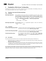
4.1.1 Process Data Structure
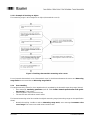
Figure 1 illustrates the structure of process data. The following provides a brief description of the individual
information.
Figure 1: Process data
4.1.1.1 Significance of the Measuring Value
The measuring value (Bit4…Bit15) has a range between 0…4095. The measuring value reflects the sensor’s
current measuring range. If the object being measured lies at the start of the measurement value range (e.g.,
50mm), a measuring value of 0 is output. If the object being measured lies at the end of the measurement
value range (e.g., 400mm) a measuring value of 4095 is output.

BA_FADK14IO-Link_V01-02-11_EN.doc 6/18 Baumer Electric AG
04.12.2012 Frauenfeld, Switzerland
4.1.1.2 Significance of the Status Information
Bit 0: Alarm
The alarm bit indicates whether an object lies within the measurement value range.
Bit0 = 0 → An object lies within the specified measuring range.
Bit0 = 1 → There is no object within the specified measuring range.
Bit 1: Switch bit
In the IO Link communication mode, the switch bit performs the function of a switching output.
Bit1 = 0 → There is no object within the the switching range.
Bit1 = 1 → An object lies within the switching range.
Bit 2: Quality
This bit provides information about the amount of light reflected by the object being measured (soiled lens
indicator).
Bit2 = 0 → The amount of reflected light exceeds the threshold (adequate signal strength).
Bit2 = 1 → The amount of reflected light lies below the threshold (weak signal strength).
Bit3: Not used
4.2 Parameters and Commands
Parameters and commands are either written to the device or read from it using SPDU (Service Protocol
Data Unit) indices. The read and write function is provided by the IO Link master. The user can write a value
to an index, or can have a value read from it.
4.2.1 Product Information
Some parameters contain product information such as the manufacturer’s name, the product name and
number, together with a user-specific sensor designation (refer to Table Fehler! Verweisquelle konnte nicht
gefunden werden., Table of General Information SPDUs).
4.2.2 Parameters
For a description of parameters, refer to Table 6.2, Table of Parameter SPDUs.
4.2.3 Commands
Commands are written to SPDU Index 0x02 (system commands). Refer to Table 6.3 Table of System Com-
mands.
4.2.4 Saving Modifications
If parameters have been modified by either directly writing to them or by a command (this also includes re-
setting to factory settings), the modifications must be permanently saved by means of Save parameters.
Failure to do this will result in the modifications being lost when the sensor is restarted. The sensor will then
use the most recently saved entries.

BA_FADK14IO-Link_V01-02-11_EN.doc 7/18 Baumer Electric AG
04.12.2012 Frauenfeld, Switzerland
5 Explanation of the Sensor Configuration
Parameters and commands can be used to configure the sensor functionalities. The following sections pro-
vide a detailed description of the various configuration options.
5.1 Teaching a User-Specific Measuring Range
5.1.1 Parameter
Measuring range work: This parameter covers the currently used beginning and end values for the
measuring range. The beginning and end values can either be entered directly
into the parameter (numerical teaching), or they can be automatically set via
the interim register to teach an object The parameter comprises two 16 bit
components: Measuring range limit A and Measuring range limit B.
- Unit: 0.1mm
- Factory setting: 50 ... 400mm
Measuring range interim: This parameter serves as a supplemental register to teach the measuring
range for an object.
- Unit: 0.1mm
5.1.2 Commands
Teach-in measuring range limit A: Command used to teach measuring range limit A. The taught value is
transferred to the interim register, Measuring range interim.
Teach-in measuring range limit B: Command used to teach measuring range limit B. The taught value is
transferred to the interim register, Measuring range interim.
Transfer measuring range: The measuring range learned in the interim register, Measuring
range interim, is transferred to the Measuring range work work reg-
ister and is set to active.
5.1.3 Description
There are two methods which the user can employ to adjust the measuring range of the FADK 14:
• Numerical teaching: The beginning and end values of the measuring range are written directly to the
Measuring range work parameter;
• Teaching an object: the beginning and end values of the measuring range are learned for an object
by applying the corresponding measuring commands. If the object lies outside the original measuring
range, the minimum or maximum measuring distance are learned.
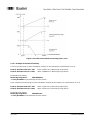
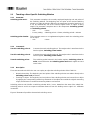
The measuring value between measuring value limits A and B is output as a relative value between 0 and
4095. Measuring value limits A and B are output as absolute distances from the leading sensor edge in 0.1
millimeter increments. Figure 2 illustrates possible characteristic measuring value curves.

BA_FADK14IO-Link_V01-02-11_EN.doc 8/18 Baumer Electric AG
04.12.2012 Frauenfeld, Switzerland
Figure 2: Possible characteristic measuring value curves
5.1.3.1 Example of Numerical Teaching:
1) The measuring range is to be set between 150mm (A) and 300mm (B) (characteristic curve 2).
Point A, absolute value in 0.1 mm: 1500 05DC hex (= Measuring range limit A)
Point B, absolute value in 0.1 mm: 3000 0BB8 hex (= Measuring range limit B)
Parameter to be written:
Measuring range work: 05DC0BB8 hex
Save parameters to permanently store the values!
2) An inverted measuring range is to be set between 200mm (B) and 400mm (A) (characteristic curve 3).
Point A, absolute value in 0.1 mm: 4000 0FA0 hex (= Measuring range limit A)
Point B, absolute value in 0.1 mm: 2000 07D0 hex (= Measuring range limit B)
Parameter to be written:
Measuring range work: 0FA007D0 hex
Save parameters to permanently store the values!

BA_FADK14IO-Link_V01-02-11_EN.doc 9/18 Baumer Electric AG
04.12.2012 Frauenfeld, Switzerland
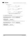
5.1.3.2 Example of Teaching an Object
The measuring range is to be taught for an object (characteristic curve 2).
Figure 3: Teaching characteristic measuring value curves
For an inverted characteristic curve (characteristic curve 3), the distance between the sensor and Measuring
range limit A must exceed that to Measuring range limit B.
5.1.4 Error Handling
The taught measuring values lie closer together than is permitted by the learnable measuring range (20mm):
• Error message: Interfering parameter (refer to: Table Fehler! Verweisquelle konnte nicht gefun-
den werden., Fault codes);
• Interim register is set to FFFF FFFF hex;
• The most recent valid values remain active.
The learned measuring value lies outside the original measuring range (measuring range on the specification
sheet):
• Numerical teaching: Unable to write to Measuring range work; error message: Parameter value
out of range. The most recent valid values remain active.

BA_FADK14IO-Link_V01-02-11_EN.doc 10/18 Baumer Electric AG
04.12.2012 Frauenfeld, Switzerland
5.2
Teaching a User-Specific Switching Window
5.2.1 Parameter
Switching points work: This parameter comprises the currently employed beginning and end points of
the switching window. The beginning and end point of the desired switching
window can either be directly defined in the parameter (numerical teaching), or
it can be automatically set via the interim register when an object is being
taught. The parameter comprises two 16 bit components: Switching point A
and Switching point B.
- Unit: 0.1mm
- Factory setting: Switching point A = 50mm; switching point B = 400mm
Switching points interim: This parameter serves as a supplemental register to teach the switching points
for an object.
- Unit: 0.1mm
5.2.2 Commands
Teach-in switching point A: Command to teach switching point A. The taught value is transferred to the
interim register, Switching points interim.
Teach-in switching point B: Command to teach switching point B. The taught value is transferred to the
interim register, Switching points interim.
Transfer switching points: The switching points learned in the interim register, Switching points in-
terim, are transferred to the Switching points work work register and and
set to active.
5.2.3 Description
There are two methods which the user can employ to adjust the switching window of the FADK 14:
• Numerical teaching: The beginning and end points of the switching window are written directly to the
Switching points work parameter;
• Teaching an object: The beginning and end points of the switching window are learned for an object
by applying the corresponding measuring commands. If the object lies outside the original measuring
range, the minimum or maximum measuring distance are learned.
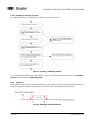
Switching points A and B define a switching window which, in turn, determines the state of the switch bits.
Switching points A and B are output as absolute distances from the leading sensor edge in 0.1 millimeter
increments.
Figure 4 illustrates all possible characteristic switching curves.

BA_FADK14IO-Link_V01-02-11_EN.doc 11/18 Baumer Electric AG
04.12.2012 Frauenfeld, Switzerland
Figure 4: Possible characteristic switching curves
5.2.3.1 Example of Numerical Teaching:
1) A switching window is to be set between 150mm (A) and 300mm (B) (characteristic curve 2).
Point A, absolute value in 0.1 mm: 1500 05DC hex (= Switching point A)
Point B, absolute value in 0.1 mm: 3000 0BB8 hex (= Switching point B)
Parameter to be written:
Switching points work: 05DC0BB8 hex
Save parameters to permanently store the values!
2) An inverted switching window is to be set between 200mm (B) and 400mm (A) (characteristic curve 3).
Point A, absolute value in 0.1 mm: 4000 0FA0 hex (= Switching point A)
Point B, absolute value in 0.1 mm: 2000 07D0 hex ( = Switching point B)
Parameter to be written:
Switching points work: 0FA007D0 hex
Save parameters to permanently store the values!

BA_FADK14IO-Link_V01-02-11_EN.doc 12/18 Baumer Electric AG
04.12.2012 Frauenfeld, Switzerland
5.2.3.2 Example of Teaching an Object
The switching window is to be taught for an object (characteristic curve 2).
Figure 5: Teaching a switching window
For an inverted switching window (characteristic curve 3), the distance between the sensor and Switching
point A must exceed that to Switching point B.
5.2.4 Hysteresis
In the approach direction to the switching window, the sensor switches at the precisely the learned switching
points. If the switching window is then exited, a hysteresis value is then added (refer to Figure 6).
Figure 6: Switching window hysteresis

BA_FADK14IO-Link_V01-02-11_EN.doc 13/18 Baumer Electric AG
04.12.2012 Frauenfeld, Switzerland
5.2.5 Error Handling
The learned switching points lie closer together than permitted in the minimum teachable switching window
(10mm):
• Error message: Interfering parameter (refer to: Table Fehler! Verweisquelle konnte nicht gefun-
den werden., Fault codes);
• Interim register is set to FFFF FFFF hex;
• The most recent valid values remain active.
The learned switching points lie outside the original measuring range (measuring range on the specification
sheet):
• Numerical teaching: Unable to write to Switching points work, error message: Parameter value
out of range. The most recent valid values remain active.
5.3 Soiled Lens Indicator
5.3.1 Parameter
Nominal value
Quality parameter: Limit value for assessing the receiving signal quality. If the received amount of
light falls below this adjustable limit, the process data quality bit is set.
- Value range: 1-8
- Factory setting: 7
Quality parameter: Actual reception quality.
5.3.2 Description
The sensor’s illumination controller allows a determination of whether adequate signal reserves still exist, in
order to provide reliable measurements. This signal reserve is indicated quantitatively by the Quality pa-
rameter. Should the Quality parameter drop below the value specified in the Nominal value quality pa-
rameter, this is displayed in the quality bit of the process data.
Application example:
When setting up an application, reading the Quality parameter on a regular basis can help determine what
its lowest value is. The threshold of the Nominal value quality parameter can then be defined 1-2 steps
lower. If, during actual operation, the Quality parameter drops below this threshold value for whatever rea-
son, a signal is output. At this point, the application continues to operate normally, the sensor should, howev-
er, be inspected as soon as feasible. Some reasons why the Quality parameter is activated include the
following:
Sensor dirty Sensor must be cleaned;
Sensor incorrectly adjusted Sensor must be readjusted;
Some factor in the application may have changed, e.g., an alteration to the object’s surface
features Sensor (Nominal value quality parameter) needs to be readjusted.
This function helps prevent the failure of the sensor by permitting appropriate countermeasures to be taken.
Important: The sensor will still continue to provide problem-free operation, even at a Quality parameter
of only 1. As high as possible a value does not necessarily need to be set!

BA_FADK14IO-Link_V01-02-11_EN.doc 14/18 Baumer Electric AG
04.12.2012 Frauenfeld, Switzerland
5.4 Average Value Formation
5.4.1 Parameter
Average: Number of measurements for which an average is formed.
- Value range: 0, 2, 4, 8, 16
- Factory setting: 0 (no average value formation)
5.4.2 Description
Forming an average of an adjustable number of measuring values helps to reduce measurement noise, and
thus increase the sensor’s reproducibility and resolution. This reduces the response speed, but the measur-
ing speed remains unaltered.
Floating average algorithm (average value sliding in one direction)
x-order average value: Y_n = (Yn + Yn-1 + Yn-2 +...+ Yn-x)/x
5.5 Switching Output Function
5.5.1 Parameter
Output function
switching output: The function carried out on the switching output in the SIO-Mode can be defined.
- Value range: 0, 1, 2
- Factory setting: 0 (Alarm)
5.5.2 Description
Process data status bits (alarm, switch bit, quality) can be applied to the sensor’s switching output. This al-
lows, for example, a soiled lens indicator to be utilized in the SIO mode. The factory setting at the switching
output indicates when the object lies outside the measurement range.

BA_FADK14IO-Link_V01-02-11_EN.doc 15/18 Baumer Electric AG
04.12.2012 Frauenfeld, Switzerland
6 Overview of SPDUs
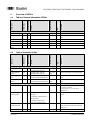
6.1
Table of General Information SPDUs
SPDU name
SPDU index
Number of Bytes
Format
Range of values
R/W
Comments
General information on sensors
Vendor Name 0X10 18 String ASCII R “Baumer Electric AG“ for all sensors
Product Name 0X12 22 String ASCII R Corresponds with Baumer article descrip-
tion
Product ID 0X13 8 String ASCII R Corresponds with Baumer article number
Serial Number 0X15 4 String ASCII R Baumer P-Code
Firmware Revision 0X17 8 String ASCII R Baumer Firmware Revision
Application Specific
Name
0X18 8 - - R/W 8 Byte at customer disposal
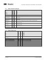
6.2 Table of Parameter SPDUs
SPDU name
SPDU index
Number of Bytes
Format
Range of values
R/W
Comments
Measuring range and switching points
Switching points
work
0X40 4 Switching point A (HB, LB)
Switching point B (HB, LB)
500…4000 R/W Distance information on switching points
Switching points
interim
0X41 4 Switching point A (HB, LB)
Switching point B (HB, LB)
500…4000,
65535
R Distance information on switching points
Measuring range
work
0X42 4 Measuring range limit A (HB, LB)
Measuring range limit B (HB, LB)
500…4000 R/W Distance information on measuring range
limits
Measuring range
interim
0X43 4 Measuring range limit A (HB, LB)
Measuring range limit B (HB, LB)
500…4000,
65535
R Distance information on measuring range
limits
Sensor functions
Average 0X50 1 - 0,1,2,4,8,
16
R/W Number of measuring cycles across which
an average is formed.
Average value = 0 or 1: Average is
switched off.
Output function
switching output
0X62 1 0 = ON, if there is no valid signal
within MB
1 = Switching output defined by
switching points
2 = ON if signal falls below
excess gain signal threshold
0,1,2 R/W Indicates what function is available on the
output.
Nominal value
quality parameter
0X65 1 1..8 R/W Provided the internal quality parameter
drops below this threshold, the switching
output is set.
Quality parameter 0X66 1 1..8 or 255 R

BA_FADK14IO-Link_V01-02-11_EN.doc 16/18 Baumer Electric AG
04.12.2012 Frauenfeld, Switzerland
6.3 Table of System Commands
Name of Com-
mand
SPDU Index
CMD Value
Comments
Restore factory setting 0X02 0X82 Restores all original factory settings of the sensor
Teach-in
switching point A
0X02 0XA0 Teach-in of switching point A. The measured distance is written into the interim switching
points register.
Teach-in
switching point B
0X02 0XA1 Teach-in of switching point B. The measured distance is written into the interim switching
points register.
Transfer
switching points
0X02 0XA2 Transfer of the switching points from the interim register to the working register.
Teach-in measuring
range limit A
0X02 0XA3 Teach-in of measuring range limit A. The measured distance is written into the measuring
range interim register
Teach-in measuring
range limit B
0X02 0XA4 Teach-in of measuring range limit B. The measured distance is written into the measuring
range interim register.
Transfer
measuring range
0X02 0XA5 Transfer of the measuring range from the interim register to the working register
Save parameters 0X02 0XE0 Save all parameters in Flash memory
6.4 Table of Fault Codes
Error Case
Error Code 1
Error Code 2
Description of
Error Codes
Communication error
(Checksum, …)
0x10 0x00 Communication error, No details
Length of written SPDU is wrong 0x10 0x00 Communication error, No details
Reading an unimplemented SPDU 0x80 0x11 Device error, Index not available
Writing to an unimplemented SPDU 0x80 0x11 Device error, Index not available
Reading Index 2 0x80 0x23 Device error, Access denied
Writing to a read only SPDU 0x80 0x23 Device error, Access denied
Writing an unimplemented System Command 0x80 0x23 Device error, Access denied
Distance between two taught points too small 0x80 0x40 Device error, Interfering parameter
Written parameter out of defined range 0x80 0x30 Device error, Parameter value out of range

BA_FADK14IO-Link_V01-02-11_EN.doc 17/18 Baumer Electric AG
04.12.2012 Frauenfeld, Switzerland
6.5 Table of Factory Settings
SPDU name
SPDU index
Default value
Application Specific Name 0X18 empty
Switching points work 0X40 Switching point A: 50mm
Switching point B: 400mm
Measuring range work 0X42 Measuring range limit A: 50mm
Measuring range limit B: 400mm
Average 0X50 0 (no average value formation)
Output function switching output 0X62 0 (Alarm)
Nominal value
quality parameter
0X65 7

BA_FADK14IO-Link_V01-02-11_EN.doc 18/18 Baumer Electric AG
04.12.2012 Frauenfeld, Switzerland
Baumer worldwide
Braz
il
Baumer do Brasil Ltda
BR-04726-001 São Paulo-Capital
Phone +55 11 56410204
Canada
Baumer Inc.
CA-Burlington, ON L7M 4B9
Phone +1 (1)905 335-8444
China
Baumer (China) Co., Ltd.
CN-201612 Shanghai
Phone +86 (0)21 6768 7095
Denmark
Baumer A/S
DK-8210 Aarhus V
Phone +45 (0)8931 7611
France
Baumer SAS
FR-74250 Fillinges
Phone +33 (0)450 392 466
Germany / Austria
Baumer GmbH
DE-61169 Friedberg
Phone +49 (0)6031 60 070
India
Baumer India Private Ltd.
IN-411038 Pune
Phone +91 (0)20 2528 6833
Italy
Baumer Italia S.r.l.
IT-20090 Assago, MI
Phone +39 (0)245 70 60 65
USA
Baumer Ltd.
US-Southington , CT 06489
Phone +1 (1)860 621-2121
United Kingdom
Baumer Ltd.
GB-Watchfield, Swindon, SN6 8TZ
Phone +44 (0)1793 783 839
Singapore
Baumer (Singapore) Pte. Ltd.
SG-339412 Singapore
Phone +65 6396 4131
Sweden
Baumer A/S
SE-56122 Huskvarna
Phone +46 (0)36 13 94 30
Switzerland
Baumer Electric AG
CH-8501 Frauenfeld
Phone +41 (0)52 728 1122
Headquarters
Baumer Electric AG
CH-8501 Frauenfeld
Phone +41 (0)52 728 1122
www.baumer.com/worldwide
Technische Änderungen und Irrtum vorbehalten.
Technical data has been fully checked, but accuracy of printed matter not guaranteed.
-
 1
1
-
 2
2
-
 3
3
-
 4
4
-
 5
5
-
 6
6
-
 7
7
-
 8
8
-
 9
9
-
 10
10
-
 11
11
-
 12
12
-
 13
13
-
 14
14
-
 15
15
-
 16
16
-
 17
17
-
 18
18


Baumer FADH 14U4470/IO Operating instructions
- Type
- Operating instructions
Ask a question and I''ll find the answer in the document
Finding information in a document is now easier with AI
Related papers
-
Baumer FADK 14U4470/S14/IO Operating instructions
-
Baumer UNCK 09G8914/KS35A/IO Operating instructions
-
Baumer FNDK 14G6904/IO Operating instructions
-
Baumer IR18.D08L-Q60.UAME.7BF Operating instructions
-
Baumer OM70-L0250.HH0240.VI Operating instructions
-
Baumer O300.GP-GW1J.72N/E022 Operating instructions
-
Baumer PFMH User guide
-
Baumer PF20S Operating instructions
-
Baumer IR18.D03K-F60.IA1E.7FO/B015 Operating instructions
-
Baumer LBFH Operating instructions
Other documents
-
APC 200KVA PDU w/ 480 PRI 208/120 SEC K 13 XMER Installation guide
-
Panasonic HG-C1000L Series User manual
-
 Sunx FX-302 Operating instructions
-
Beckhoff EP6228 Documentation
-
SIMARINE CARAVAN SPDU-52 User manual
-
APC PD300G6FK1 Specification
-
Continental G12N400G1 User manual
-
SICK DT50-2 PRO Distance sensor Operating instructions
-
-
