Air Handler
01/15
711247A
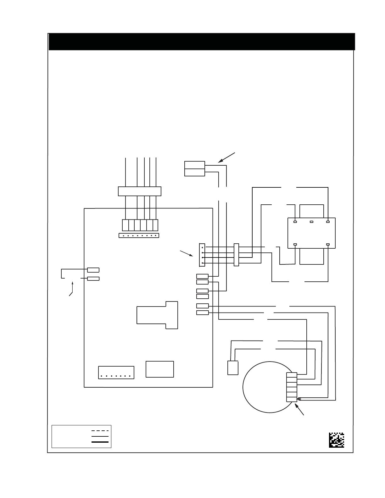
NOTES:
1. The blower motor speed tapconnection may not be as shown.
See the Installation Instructions.
2. Disconnect all power beforeservicing.
3. Transformer may have a dual voltage primary tap.
Match the tap position with the supply voltage used.
4. If the internal wiring is replaced, use only 105°C
copper wire of the same gauge.
Remarques
1. Le connecteur de vitesse du moteur du ventilateur peut
différer de l’illustration. Consultez les Instructions
d’installation.
2. Débranchez toutes les sources d’alimentation avant
l’entretien.
3. Le transformateur peut avoir un robinet principal à
double tension. Agencez la position du robinet au type
de tension de l’installation.
4. Si le câblage interne est remplacé, utilisez seulement un
fil de cuivre 105° C du même gabarit.
WIRING DIAGRAM
FIELD WIRING
LEGEND:
LOW VOLTAGE
HIGH VOLTAGE
(Replaces 7112470)
CAP.
1
3
5
2
1
2
4
6
HEATER PLUG
RELAY
Y
L2
W
G
R
C
R
C
L2
L1
-
7 6 5 4 3 2 1
1=COM
2=CAP.
3=CAP.
4=HI
5=MED
6=LOW
240
24 V
208 COM
TRANSFORMER
R
C
LOCATION OF
“T” CONNECTOR
MOTOR
3-SPEED
4-PIN PLUG (18)
L1
EAC
COOL
HEAT
RELAY
CUT WIRES TO REMOVE PLUG HOUSING
WHEN HEATER KIT NOT INSTALLED
BLACK
RED
WHITE
BROWN
BROWN
BLACK
RED
YELLOW
WHITE
GREEN
GRAY
RED
RED
BLACK
BLW DTC
R
BLACK
IF BOARD
EQUIPPED
WITH
BLWDTC
TERMINAL
WHITE
GRAY
