
“4069ERT” Service and Parts Manual March 2014
Page 5-1
Section 5
S
CHEMATICS
C
ONTENTS
P
AGE
Hydraulic Schematics Table . . . . . . . . . . . . . . . . . . . . . . . . . . . . . . . . . . . . . . . 5-2
Hydraulic Schematic . . . . . . . . . . . . . . . . . . . . . . . . . . . . . . . . . . . . . . . . . . . . 5-3
Electrical Schematics . . . . . . . . . . . . . . . . . . . . . . . . . . . . . . . . . . . . . . . . . . . . 5-5
F
IGURES
P
AGE
Hydraulic Schematic . . . . . . . . . . . . . . . . . . . . . . . . . . . . . . . . . . . . . . . . . . . . 5-3
Functions Manifold . . . . . . . . . . . . . . . . . . . . . . . . . . . . . . . . . . . . . . . . . . . . . . 5-4
Electrical Schematic, 1 of 3 . . . . . . . . . . . . . . . . . . . . . . . . . . . . . . . . . . . . . . . 5-5
Electrical Schematic, 2 of 3 . . . . . . . . . . . . . . . . . . . . . . . . . . . . . . . . . . . . . . . 5-6
Electrical Schematic, 3 of 3 . . . . . . . . . . . . . . . . . . . . . . . . . . . . . . . . . . . . . . . 5-7

“4069ERT” Service and Parts ManualMarch 2014
Page 5-2
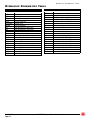
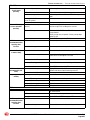
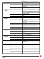
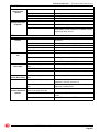
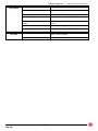
HYDRAULIC SCHEMATICS TABLE -
H
YDRAULIC
S
CHEMATICS
T
ABLE
Callout Description
CBV1, CBV2 Counterbalance Valve, Drive
CV1 Check Valve
CV2 Check Valve
CV4 Check Valve
CYL1 Cylinder, Upper Lift
CYL2 Cylinder, Lower Lift
CYL3-CYL4 Cylinder, Steer
CYL5-8 Cylinder, Outrigger
EP1 Pilot Operated Valve, Mid Speed
EP2 Pilot Operated Valve, Low Speed
FD1 Flow Divider, Drive Mid & Low
FD2 Flow Divider, Drive Mid & Low
FR1 Flow Regulator Valve, Brake Apply
HLS1 Shuttle Valve, Brake Release
HP1 Hand Pump, Brake Release
MLF Motor, Left Front
MLR Motor, Left Rear
MP1 Manual Operated Valve, Brake Release
MRF Motor, Right Front
MRR Motor, Right Rear
ORF1 Orifice, Steer Speed .063
ORF3 Orifice, Flow Divider Bypass.025
ORF4 Orifice, Flow Divider Bypass.025
ORF5 Orifice, Bypass Control .060
P1 Pump
PD1 Pilot Operated Valve, High Torque Shift
PD2 Pilot Operated Valve, Mid Range Shift
PD3 Pilot Operated Valve, High Torque Shift
RV1 Relief Valve, Main
RV2 Relief Valve, Lift
SV1 Solenoid Valve, High Speed
SV10-SV17 Solenoid Valve, Outrigger
SV18 Solenoid Valve, Down Valve, Upper Lift Cyl
SV2 Solenoid Valve, High Torque
SV3 Solenoid Valve, Outrigger Directional
SV4 Solenoid Valve, Rear Wheel Bypass
SV5 Solenoid Valve, Rear Wheel Bypass
SV6 Solenoid Valve, Steer Directional
SV7 Solenoid Valve, Platform Lift
SV8 Solenoid Valve, Rear Wheel Bypass
SV9 Solenoid Valve, Down Valve, Lower Lift Cyl
SVCL1 Solenoid Valve, Drive Forward
SVCL2 Solenoid Valve, Drive Reverse
Callout Description

“4069ERT” Service and Parts Manual March 2014
Page 5-3
HYDRAULIC SCHEMATIC -
H
YDRAULIC
S
CHEMATIC
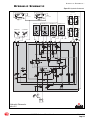
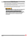
Figure 5-1: Hydraulic Schematic
ART_4508
Hydraulic Schematic
4069 ERT
RIGHT SIDE
STEER CYLINDER
LEFT SIDE
STEER CYLINDER
LEFT FRONT
WHEEL MOTOR/BRAKE
RIGHT REAR
WHEEL MOTOR/BRAKE
RIGHT FRONT
WHEEL MOTOR/BRAKE
LEFT REAR
WHEEL MOTOR/BRAKE
ø.047
LOWER
LIFT CYLINDER
UPPER
LIFT CYLINDER
ø.073
LF
RR
LR
RF
A B
A
B
AB
A
B
SV10
SV12
SV11
SV13
SV14
SV16
SV15
SV17
SV18
SV9
OUTRIGGERS
RV3
2500 PSI
CYL1
CYL1
CYL2
CYL2
CYL3
CYL3
CYL4
CYL4
CYL8
CYL8
CYL6
CYL6
CYL7
CYL7
CYL5
CYL5
MRR
MRR
MLF
MLF
MRF
MRF
MLR
MLR
P1
P1

“4069ERT” Service and Parts ManualMarch 2014
Page 5-4
HYDRAULIC SCHEMATIC -
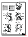
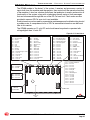
Figure 5-2: Functions Manifold
ART_4471
Functions Manifold
4069
Left Side
Of Machine
Front
Of Machine
Center
Of Machine
Rear
Of Machine
SOLENOID VALVE – DRIVE FORWARD
PILOT OP. VALVE – MID SPEED
RELIEF VALVE – MAIN
RELIEF VALVE – PLATFORM LIFT
FLOW REGULATING VALVE- BRAKE APPLY
SHUTTLE VALVE – BRAKE RELEASE
ORIFICE – STEER SPEED CONTROL
ORIFICE – FLOW DIVDER BYPASS
PILOT OP. VALVE – HIGH TORQUE SHIFT
SOLENOID VALVE – DRIVE REVERSE
PILOT OP. VALVE – LOW SPEED
ORIFICE – FLOW DIVDER BYPASS
PILOT OP. VALVE – HIGH TORQUE SHIFT
PILOT OP. VALVE – MID RANGE SHIFT
COUNTERBALANCE VALVE – DRIVE
COUNTERBALANCE VALVE – DRIVE
ORIFICE – BYPASS CONTROL
SOLENOID VALVE – OUTRIGGER DIRECTIONAL
SOLENOID VALVE – HIGH TORQUE
SOLENOID VALVE – REAR WHEEL BYPASS
SOLENOID VALVE – HIGH SPEED
FLOW DIVIDER VALVE – DRIVE MID & LOW
MANUAL OP. VALVE – BRAKE EMR. RELEASE
COIL #10
COIL # 8
CHECK VALVE - ANTI CAVITATION
HAND PUMP – BRAKE RELEASE
CHECK VALVE - ANTI CAVITATION
CHECK VALVE - ANTI CAVITATION
SOLENOID VALVE – REAR WHEEL BYPASS
SOLENOID VALVE – STEER DIRECTIONAL
SOLENOID VALVE – PLATFORM LIFT
FLOW DIVIDER VALVE – DRIVE MID & LOW
SOLENOID VALVE – REAR WHEEL BYPASS

“4069ERT” Service and Parts Manual March 2014
Page 5-5
HYDRAULIC SCHEMATIC -
N
OTES
:

“4069ERT” Service and Parts ManualMarch 2014
Page 5-6
ELECTRICAL SCHEMATICS -
E
LECTRICAL
S
CHEMATICS
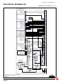
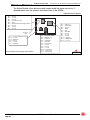
Figure 5-3: Electrical Schematic, 1 of 3
ART_4509
Electrical Schematic, 1 of 3
4069ERT
/2:(5&21752/%2;
02'8/(7%0
7(50,1$/%/2&.
%
%
83
'2:1
6(/(&7
%$6(3/$7)250
+2850(7(5
$66(0%/<
'2:1',2'(
(6723
'2:1
(0(5*(1&<
%5($.(5
$
$/$50
3
3
3
3
3
3
$//&,5&8,76921/<
0,&52352&(6625
*3
*5281'
&$1%86/2
&$1%86+,
3
3
3
3
3
3
3
3
3
+2850(7(5
+,*+63(('
+,*+72548(
$/$50
'5,9(5(9(56(
'5,9()25:$5'
67((5/()7
67((55,*+7
/,)79$/9(
0$1,)2/'0,6&
3
3
3
3
3
3
3
/)2875,**(5'2:1
5)2875,**(5'2:1
/52875,**(583
552875,**(583
/)2875,**(583
5)2875,**(583
3
3
3
3
3
'2:16:,7&+
3/$7)2506(/(&7('
836:,7&+
%$6(6(/(&7('
9$/9(6833/<
*5281'
*5281'
*5281'
7%0$1$/2*,1
35(6685(75$16'8&(5
&((/(9$7,21
(/(9$7,2175$16'8&(5
3
3
%$6(/2:(5&21752/6
3
3
/2$'6(16(&(
3
3
3
3
3
3
3
3
'2:19$/9(
/,1(&217$&725
5($5:+((/%<3$669$/
/56:,7&+,1387
2875,**(56:,7&+(6
3
3
3
3
3
556:,7&+,1387
5)6:,7&+,1387
/)6:,7&+,1387
552875,**(5'2:1 3
3
/52875,**(5'2:1
32875,*(;7(1'9$/
3
2875,*5(75$&79$/
1
2
3
4
LOWER CONTROL
BOX DOOR
404
405
00
00
15
105
5
105
414
413
412
417
20
5
204
107
108
111
110
313
213
411
168
169
63
61
65
67
62
60
64
66
1
405
406
404
409
43
407
42
15
15
15
75
76
77
78
411
37
37
117
117
92/70(7(5
516
000
105 000
516
415
416
OUTPUTS
15
REAR WHEEL BYPASS VAL P4-3
BEACON, CE OPTION P6-8
J1
DEUTSCH
70 PIN
J2
DEUTSCH
4 PIN
126
126
106
106
15
405
416
404
1

“4069ERT” Service and Parts Manual March 2014
Page 5-7
ELECTRICAL SCHEMATICS -
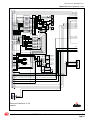
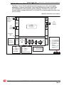
Figure 5-4: Electrical Schematic, 2 of 3
ART_4510
Electrical Schematic, 2 of 3
4069ERT
0$,10$1,)2/'
1
2
12
1
2
1
2
1
2
1
2
OUTRIGGER
CYLINDERS
1
2
12
J6
J5
1
2
3
4
HEIGHT 2
(CE ONLY)
DEUTSCH
12 PIN
DEUTSCH
12 PIN
DEUTSCH
6 PIN
DEUTSCH
6 PIN
OUTRIGGER
SWITCHES
RF
LF
RR
LR
DOWN VALVES
62
60
64
66
65
67
61
63
15
15
RF DOWN
LF DOWN
RR DOWN
LR DOWN
RR UP
LR UP
LF UP
RF UP
LIFT
STEER RT
STEER LT
FORWARD
REVERSE
TORQUE
SPEED
43
42
407
1
15
105
15
J7
J4
516
404
405
416
000
GROUND
BUSS 1
73
WHEEL BYPASS
WHEEL BYPASS
(BRN)
(BLK)
(BLU)
21
2
1
OUTRIGGER EXT
OUTRIGGER RET
1
2
3
ANGLE
TRANSDUCER
HEIGH 1
1
2
3
PRESSURE
TRANSDUCER
(CE ONLY)
1
2
3
ANGLE
TRANSDUCER
78
15
A
B
C
A
B
C
A
B
C
A
B
C
A
B
C
1
2
1
2
ANSI BEACON
CE BEACON
WHEEL BYPASS
BEACON CONNECTION
PIN A. FOR ANSI
PIN B. FOR CE
J1
DEUTSCH
70 PIN
J2
DEUTSCH
4 PIN
126
106
15
000
516
15
516
15
408
408
408
405
404
416
48V
48V
20
15
416

“4069ERT” Service and Parts ManualMarch 2014
Page 5-8
ELECTRICAL SCHEMATICS -
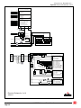
Figure 5-5: Electrical Schematic, 3 of 3
ART_4511
Electrical Schematic, 3 of 3
4069ERT
%51
%/8 <(/
25*
%/.
%$5(
5('
$
%$776:,7&+
DEUTSCH
6 PIN
J4
P600
PUMP MOTOR CONTROLLER
48V D/C TO 12V CONVERTER
P6-1 CAN BUS HI
P6
P6-2 CAN BUS LO
P6-3 GROUND
P7-1 CAN BUS HI P7
P7-2 CAN BUS LO
P7-3 GROUND
P8-1 48V INPUT
P8
P8-2 48V INPUT
P1-1 12 VOLT SYSTEM POWER
P1
P1-2 12 VOLT SYSTEM POWER
P1-3 12 VOLT SYSTEM POWER
P1-4 BASE SELECTED
P1-5 PLATFORM SELECTED
P1-6 12 VOLT E-STOP CIRCUIT
MB+
B-
M
1
2
92/76 92/76 92/76 92/76
92/76
92/76 92/76
92/76
-
--
-
-
-
-
-
+
+
+
+
++
+
+
48 VOLTS BATTERY PACK
$
$
CHARGER
DEUTSCH
2 PIN
CHARGER
INTERLOCK
BATTERY
8 HP
MOTOR
CONTACTOR
408
408
408
405
404
416
48V
48V
DEUTSCH
2 PIN
HORN
LIFT/DRIVE
TILT IND LIGHT
7,/7$/$50
DRIVE ENABLE
ENABLE
ST RIGHT
ST LEFT
REV/UP
FWD/DWN
POT
OVERLOAD
P3
P3-1
P3-2
P3-4
P3-5
DRIVE
LIFT
SWITCH COMMON
SWITCH COMMON
P2-4
P2-5
P2-10
P2-11
P2-12
P2
ENABLE BAR
POT CENTER
POTENTIOMETER
POTENTIOMETER
P4-4
P4-5
P4
TILT IND. LAMP
TILT ALARM
P1
P1-1
SWITCH POWER
12 VOLT + INPUT
CAN BUS H
GROUND
CAN BUS L
P1-3
P1-4
P1-6
P2-6
GP400 MATRIX MODULE
P2-3
P2-2
P2-1
P4-6
DRIVE ENABLE
P3-10
P3-11
OUTRIGGERS UP
OUTRIGGERS DOWN
FORWARD/DOWN
REVERSE/ UP
STEER LEFT
STEER RIGHT
P4-7
OVERLOAD IND.
C
D
E
F
G
H
EMERG
STOP
AUTO LEVEL
OUTRIGGERS
SPEED
DEUTSCH
6 PIN
J8
ON/OFF SWITCH
000000
516516
15
20
15
408
408
408
405
404
416
48V
48V
J9
+251
15
73

“4069ERT” Service and Parts Manual March 2014
Page 4-3
TROUBLESHOOTING -- GENERAL TROUBLESHOOTING TIPS
G
ENERAL
T
ROUBLESHOOTING
T
IPS
H
YDRAULIC
F
LUID
P
UMP
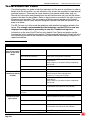
This machine operates on a “Motor Control” theory in which fluid flow volume is
controlled by varying the speed of the DC electric motor driving a tandem fixed
displacement pump. 100% of the fluid produced by the pump goes to the selected
function.
Common Causes of Electrical System Malfunctions:
• Battery connections are loose or corroded
• Battery is not fully charged.
• Emergency Stop buttons are pushed (OFF position).
• Circuit breaker is in the tripped (OFF position).
Common Causes of Hydraulic System Malfunctions:
• Hydraulic fluid level is too low.
• Mixed incompatible hydraulic fluids, destroying the additives and causing varnish build-up
and sticking valves.
• Water in the hydraulic fluid due to damp climate.
• Improper hydraulic fluid. Viscosity too high in cold climates. Viscosity too low in warm cli-
mates.
• Hydraulic fluid contaminated with debris--filter change interval neglected, or debris intro-
duced into the hydraulic system.
In machines equipped with the optional cold climate package, MEC uses a
multiple viscosity fluid that is light enough for cold climates and resists
thinning in warm climates. Use only the recommended hydraulic fluid.
Substituting with a lower grade fluid will result in pump failure. Refer to
Section 1 of this manual.
Contamination always causes failure in any hydraulic system. It is very
important to be careful not to introduce any contamination into hydraulic
system during the assembly procedures. Please make sure all ports and
cavities of the manifold and cylinders are properly capped or plugged
during maintenance activities.

“4069ERT” Service and Parts ManualMarch 2014
Page 4-4
TROUBLESHOOTING -- ELECTRICAL SYSTEM TROUBLESHOOTING
E
LECTRICAL
S
YSTEM
T
ROUBLESHOOTING
The electronic control system used on this machine was designed for low maintenance
and long trouble free operation. The system consists of two microprocessor based
modules; The Matrix Module and the GP400 Processor. They communicate through a
low voltage digital signal called Can-Bus communication.
To protect against part failure or incorrect plug connections, the modules are fully short
circuit and reverse polarity protected. All electrical plug connections are waterproof to
promote longer trouble free operation and to increase terminal life.
NEVER ATTEMPT TO SUPPLY BATTERY POWER, OR VOLTAGE HIGHER
THAN 12 VOLTS TO ANY PART OR MODULE IN THIS SYSTEM, AS
CATASTROPHIC FAILURE OF THE MODULES MAY RESULT.
USE OF HIGH PRESSURE WASHING EQUIPMENT DIRECTLY ON THE
MODULES CAN FORCE WATER INTO SEALED CONNECTION AND CAN
CAUSE A TEMPORARY SYSTEM SHUT-DOWN. HIGH PRESSURE
WASHING WITHIN THE VICINITY OF THE MODULES IS HIGHLY
DISCOURAGED.

“4069ERT” Service and Parts Manual March 2014
Page 4-5
TROUBLESHOOTING -- ELECTRICAL SYSTEM TROUBLESHOOTING
GP400 M
ODULE
The GP400 module is “the brains” of the system. It receives and processes a variety of
inputs both from the machine and the operator, then controls all the operative functions
of the machine. It also has a feature that allows the technician to access and monitor all
functionality of the system, along with a technician-friendly series of fault messages
that can be accessed through the use of the EZ-Cal scan tool. Flash codes are also
provided in case an EZ-Cal scan tool is not available.
Such information can be used for preventative maintenance and troubleshooting should
a problem arise. A comprehensive list of EZ-Cal accessible information can be found
later in this section.
The GP400 operates on 12 volts DC and should never be probed or operated with
voltage higher than 14 volts DC
Figure 4a-1: GP400 Module
ART_3185
1
3
13
15
13
10 12
1
3
13
15
1
3
13
15
1
3
13
15
1
3
1
3
1314
13
15
Diagnostic
LED
EZ-Cal
Connection
P1-1 — CAN BUS H
P1-2 — CAN BUS L
P1-3 — Ground
P2-1 — not used
P2-2 — not used
P2-3 — not used
P5-1 — Lift Valve
P5-2 — Steer Right
P5-3 — Steer Left
P5-4 — Drive Forward
P5-5 — Drive Reverse
P5-6 — Alarm
P5-7 — High Torque
P5-8 — High Speed
P5-9 — Hour Meter
P5-10 — not used
P5-11 — not used
P5-12 — not used
P5-13 — not used
P5-14 — Start Inhibit Warn
P5-15 — not used
OUTRIGGER VALVES
P6-1 — Back Pitchin
g Valve
P6-2 — Front Pitching Valve
P6-3 — Right Pitching Valve
P6-4 — Left Pitching Valve
P6-5 — not used
P6-6 — not used
P6-7 — not used
P6-8 — not used
P6-9 — not used
P6-10 — not used
P6-11 — not used
P6-12 — not used
P6-13 — Axle Lock
P6-14 — not used
P6-15 — Generator
BASE & LOWER CONTROLS
P7-1 — Valve Supply
P7-2 — Base Selected
P7-3 — UP - Base
P7-4 — Platform Selected
P7-5 — not used
P7-6 — not used
P7-7 — DOWN - Base
P7-8 — not
used
P7-9 — not used
P7-10 — Choke/Preheat
P7-11 — not used
P7-12 — Start
P7-13 — Oil Pressure Switch
P7-14 — not used
P7-15 — not used
P4-1 — Choke/Preheat
P4-2 — Starter
P4-3 — not used
P4-4 — Throttle
P4-5 — Fuel
P4-6 — Fuel
P4-7 — Alt Exciter
P4-8 — Ignition
P4-9 — not used
P4-10 — Rear Wheel Bypass Valve
P4-11 — not used
P4-12 — Proportional
P4-13 — not used
P4-14 — Down Valve 1
P4-15 — not used
P8-1 — Elevation Transducer
P8-2 — not used
P8-3 — not used
P8-4 — not used
P8-5 — CE Elevation
P8-6 — Analog IN
P8-7 — not used
P8-8 — TBM Analog IN
P8-9 — not used
P8-10 — not used
P8-11 — not used
P8-12 — not used
P8-13 — Ground
P8-14 — Ground
P8-15 — Ground
NOT USED

“4069ERT” Service and Parts ManualMarch 2014
Page 4-6
TROUBLESHOOTING -- ELECTRICAL SYSTEM TROUBLESHOOTING
M
ATRIX
M
ODULE
The Matrix Module is the remote module located inside the upper control box. It
received inputs from the operator and relays them to the GP400.
Figure 4a-2: Matrix Module
ART_3159
Matrix Module (inside Upper Control Box)
1
10
3
13
46
12
1
10
3
12
1
7
3
9
Diagnostic
LED
P4-1 — not used
P4-2 — not used
P4-3 — not used
P4-4 — Level Indicator Lamp
P4-5 — Alarm
P4-6 — DriveEnabled Lamp (Outriggers Option)
P4-7 — not used
P4-8 — not used
P4-9 — not used
P3-1 — High Speed
P3-2 — Switch Supply
P3-3 — not used
P3-4 — DRIVE
P3-5 — LIFT
P3-6 — NOT USED
P3-7 — not used
P3-8 — not used
P3-9 — not used
P3-10 — UP Switch
P3-11 — DOWN Switch
P3-12 — not used
P1-1 — 12 Volts DC INPUT: Power-up
P1-2 — not used
P1-3 — CAN BUS H
P1-4 — Ground
P1-5 — not used
P1-6 — CAN BUS L
P2-1 — FORWARD / DOWN
P2-2 — REVERSE / UP
P2-3 — STEER Left
P2-4 — STEER Right
P2-5 — Enable Bar
P2-6 — Potentiometer
P2-7 — not used
P2-8 — not used
P2-9 — not used
P2-10 — Potentiometer
P2-11 — Potentiometer
P2-12 — Switch Supply

“4069ERT” Service and Parts Manual March 2014
Page 4-7
TROUBLESHOOTING -- ELECTRICAL SYSTEM TROUBLESHOOTING
P600 M
OTOR
C
ONTROL
M
ODULE
The Motor Control Module operates the electric pump motor with varied speeds
depending on operator commands. Pulse-width Modulation provides smooth and
controlled operation with maximum battery efficiency. The Motor Controller also
converts battery voltage (48 volts DC) to 12 volts DC for use throughout the rest of the
control system.
Figure 4b-3: P600 Motor Control Module
P 600
CMEC 48V RT
21 510 601
s/n: 2071200014
P1
P8
P7
to Upper Controls
to GP400
EZ-Cal
Connection
P6
P5
To :
Pump
Motor
To :
Battery
Disconnect
Switch
To :
Battery
Ground
B+
B–
Diagnostic
LED
13
13
13
14
12
P1-1 — 12 Volts DC OUTPUT
P1-2 — 12 Volts DC OUTPUT
P1-3 — 12 Volts DC OUTPUT
P1-4 — BASE Selected
P1-5 — PLATFORM Selected
P1-6 — Output to
EMERGENCY STOP
Circuit for Module
Activation
P7-1 — CAN BUS H
P7-2 — CAN BUS L
P7-3 — Ground
P6-1 — CAN BUS H
P6-2 — CAN BUS L
P6-3 — Ground
P8-1 — 48 Volts DC INPUT
P8-2 — 48 Volts DC INPUT
ART_2572

“4069ERT” Service and Parts ManualMarch 2014
Page 4-8
TROUBLESHOOTING -- ELECTRICAL SYSTEM TROUBLESHOOTING
T
ERMINAL
B
LOCK
M
ODULE
(TBM)
Figure 4a-4: Terminal Block Module (TBM)
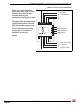
There is a module inside the
lower control box, called a TBM
(Terminal Block Module) that
provides terminal point
connections for both positive and
ground circuits. A signal from the
Emergency Stop circuit activates
a load-reduction relay within the
TBM that provides ample power
to the B+ (positive) terminal strip.
This arrangement protects the
system against voltage drop
conditions that can be
detrimental to the electrical
system.
GROUND
(B−) Connection
PLATFORM Selected
BASE Selected
ANALOG (AMP)
COMMON B+
POSITIVE OUTPUT
(B+) Supply
To various circuits
ART_3186

“4069ERT” Service and Parts Manual March 2014
Page 4-9
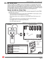
TROUBLESHOOTING -- EZ-CAL SCAN TOOL
EZ-C
AL
S
CAN
T
OOL
The EZ-Cal (MEC part # 90888; not part of the machine) is a hand-held scan tool that
interfaces with the system to provide various information and adjustments. The EZ-cal
receives its power from the GP400 when connected. The system must be powered up by
closing the Battery disconnect switch and pulling both emergency stop switches. You must
also select Base or Platform depending on the station you will operate from.
U
SING
THE
EZ-
CAL
S
CAN
T
OOL
To operate the EZ-cal, plug the cable into the 4-terminal receptacle P9 on the GP400
and power the system up.
• The EZ-Cal display will illuminate and read “HELP: PRESS ENTER”. From this point, use the
right and left arrows to scroll through the base menus.
• Once the desired base menu is obtained (i.e. ADJUSTMENTS) press Enter to access sub
menus.
• Use the right and left arrows to scroll through sub menus, press Enter again.
• The up/down arrows are used to change settings only.
• Press ESC to back up one level.
Figure 4a-5: EZ-Cal Scan Tool Connections - GP400 Module
ART_3154
SYMBOL KEY FUNCTIONS
ESC/ENTER BUTTONS
To move back and forth between menu and sub-menu
LEFT/RIGHT BUTTONS
Select menus and setting to be adjusted
UP/DOWN BUTTONS
Adjust setting values
GP400 Control Module
Calibrator
MEC P/N 90888
13
13
15
13
10 12
13
10 12
13
13
15
13
13
15
13
13
15
13
1
3
1
3
1
4
13
15
LED
GP400
Module
Diagnostic LED
Lower Controls
Terminal
Block
Module

“4069ERT” Service and Parts ManualMarch 2014
Page 4-10
TROUBLESHOOTING -- EZ-CAL SCAN TOOL
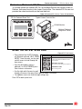
O
PTIONAL
O
NBOARD
EZ-C
AL
To use and operate the onboard EZ-Cal, set the Base/Platform Key switch to Base or
Platform, then open the door to the Lower Controls Box. The onboard EZ-Cal scan tool
provides the same functionality as the hand-held unit.
Figure 4-6: Onboard EZ-Cal Scan Tool & GP400 Module
U
SING
THE
EZ-C
AL
S
CAN
T
OOL
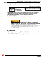
Figure 4-7: EZ-Cal Buttons
• Once, powered up, the EZ-Cal display
will illuminate and read “HELP: PRESS
ENTER”. From this point, use the right
and left arrows to scroll through the
base menus.
• Once the desired base menu is
obtained (i.e. ADJUSTMENTS) press
Enter to access sub menus.
• Use the right and left arrows to scroll
through sub menus, then press Enter again to choose a sub menu.
• The up/down arrows are used to change settings only.
Press ESC to back up one level.
ART_4164
EZ Cal Onboard Scan Tool
GP400 Module
Optional Onboard
Diagnostic Center
Ty pi cal Lower Controls Box
ART_3710
SYMBOL KEY FUNCTIONS
ESC/ENTER BUTTONS
To move back and forth between menu
and sub-menu
LEFT/RIGHT BUTTONS
Select menus and setting to be adjusted
UP/DOWN BUTTONS
Adjust setting values

“4069ERT” Service and Parts Manual March 2014
Page 4-11
TROUBLESHOOTING -- USING THE EZ-CAL WITH THE FLOW CHARTS
U
SING
THE
EZ-C
AL
WITH
THE
F
LOW
C
HARTS
Use the EZ-cal Flow Charts as a guide to locate diagnostic information and make adjust-
ments. Each box in the flow chart will have 3 bits of information.
Figure 4-8: EZ-Cal Display Example
The IDENTIFIER (5c2): – Used to locate this specific personality in the informational
charts. Here you can obtain specific information on the individual personalities.
The PERSONALITY (Up Max): – Identifies the individual personalities.
The DEFAULT SETTING: – The factory setting. If adjustments are made, they must be
returned to default setting.
ACCESS LEVEL 1 PROVIDES ACCESS TO CHANGE PERSONALITIES
NORMALLY PRESET AT THE FACTORY TO PROVIDE PROPER MACHINE
MOVEMENT AT SAFE SPEEDS. PERSONALITIES MUST NOT BE
CHANGED WITHOUT PRIOR AUTHORIZATION FROM MEC AND MAY ONLY
BE RETURNED TO FACTORY SPECIFICATION AS LISTED IN THE
FOLLOWING TABLES.
F
LASH
C
ODES
Flash Codes, provided from the GP400 red LED, will also assist in the event an EZ-cal
is not available. However, the EZ-cal yields considerably more relevant information.
Refer to "EZ-Cal HELP Messages" on page 4-18 for flash coded error messages.
UP MAX
75%
5C-2
Identification Number
Personality
Default Setting
to match with information tables, this number
will not appear on the EZ-Cal display
ART_3183

“4069ERT” Service and Parts ManualMarch 2014
Page 4-12
TROUBLESHOOTING -- USING THE EZ-CAL WITH THE FLOW CHARTS
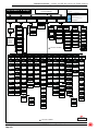
Figure 4-9: EZ-Cal Flow Chart: Adjustments and Setup
ART_4512
Adjustments & Setups
69 ELECTRIC SERIES
EZ-CAL MENU
SYMBOL KEY FUNCTIONS
EZ-Cal Flow Chart
Chart 1 of 2
ESC/ENTER BUTTONS
To move back and forth between
Menu and sub-menu
LEFT/RIGHT BUTTONS
Select menus and setting to be adjusted
UP/DOWN BUTTONS
Adjust setting values
HELP
PRESS ENTER
1
DIAGNOSTICS
2
ACCESS LEVEL
3
ADJUSTMENTS
4
SETUPS
5
ENTER
ERROR
MESSAGE
ENTER
LOGGED
MESSAGES
PRESS RT & LT
ARROWS TO VIEW
PREVIOUS
ERRORS &
MESSAGES
ENTER
SYSTEM
2A
PLATFORM
2B
GROUND
2C
INPUTS
2D
ANALOGS
2E
SEE
CHART
# 2
ACCESS LEVEL
2 FOR
CALIBRATIONS
ACCESS LEVEL
1 FOR
ADJUSTMENTS
ENTER
ENTER
OUTPUTS
2F
SPEED
37%
4D-1
4D-2
4D-3
ELEV DRIVE
COMP
10%
4D-4
EXCEL
0.2 SEC
4D-5
DRIVE
4A 4B 4C
STEER
4D 4E
OUTRIGGERS
OPTIONAL
4F
TILT
4J
ALARMS
4M
UP MIN
5%
4C-1
UP MAX
65%
4C-2
DOWN MIN
0%
4C-3
DOWN MAX
0%
4C-4
ACCEL
3 SEC
4C-5
DECEL
1.0
4C-6
FWD MIN
1%
4A-1
FWD MAX
90%
4A-2
REV MIN
1%
4A-3
REV MAX
90%
4A-4
ACCEL
2.0 SEC
4A-5
DECEL
0.5 SEC
4A-6
STOP DECEL
1.0 SEC
4A-7
FWD MIN
1%
4B-1
FWD MID
25%
4B-2
FWD MAX
55%
4B-3
REV MIN
1%
4B-4
REV MID
21%
4B-5
REV MAX
55%
4B-6
OUT MIN
20%
4E-1
OUT MAX
100%
4E-2
IN MIN
20%
4E-3
IN MAX
100%
4E-4
ACCEL
3.0 SEC
4E-5
DECEL
3.0 SEC
4E-6
OUTRIGGERS
0= NO or
3= DRV RET
4F-1
EXTEND
60%
4F-2
LEVEL
20%
4F-3
RETRACT
60%
4F-4
DEBOUNCE
0.10 SEC
4F-5
INITIAL
0.1 SEC
4F-6
X TRIP
5.0°
4J-1
Y TRIP
3.0°
4J-2
DELAY TRIP
2.0 SEC
4J-3
DELAY CLEAR
0.5 SEC
4J-5
DRIVE
SELECT AS
NEEDED
4M-1
LIFT
2= DOWN +
SELECT AS
NEEDED
4M-2
ENTER ENTERENTER ENTER ENTER ENTER ENTER
ENTER
CHANGE
DEFAULTS
5A
TILT
SETUPS
5B
HEIGHT
SETUPS
5C
LOAD
SETUPS
5D
INTERLOCKS
5E
CALIBRATE LEVEL
SEE INSTRUCTIONS
5B-1
TILT SHUTDOWN
0= NEVER
5B-2
ELEVATED TILT
SHUTDOWN
1=LIFT & DRIVE
5B-3
5C-1
ELEVATION @
8%
5C-2
CALIBRATE HEIGHT
SEE INSTRUCTIONS
5C-5
TILT CORRECTION
1= X+
5C-4
SAMPLES@
0.30 SEC
5C-6
SLOW DOWN
10%
5A-1
5A-2
CUSTOMER
15= 4069ES
5E-1
TRIGGER ONLY
10.0 SEC
5E-5
STARTER DELAY
10.0 SEC
5E-2
5E-3
5D-1
CALIBRATE LOAD
SEE INSTRUCTIONS
5D-2
FAULTY LOAD
-100%
5D-3
DYNAMIC SCALE
.95
ENTER
ENTER
ENTER
ENTER ENTER
ENTER
5C-3
MIN LIFT
1.0 SEC
5D-4
DELAY UP
0.0 SEC
5D-5
DELAY DOWN
0.0 SEC
= DO NOT CHANGE
= DO NOT CHANGE
PRE- LEVEL
1.4 SEC
4F-7
4F-8
OVERLOAD
4K
TRIP @
0% ANSI
110% CE
4K-1
LAMP @
0%
4K-2
ALARM @
0%
4K-3
@ HEIGHT
8%
4K-4
SAFE DOWN
20%
4K-5
DELAY TRIP
1.5 SEC
4K-6
DELAY CLEAR
1.5 SEC
4K-7
ENTER
5E-4
TRIGGER WAIT
0.0 SEC
FUNCTION HOLD
0.2 SEC
THROTTLE
DELAY
0.0 SEC
RUN SYSTEM
TESTS
DRIVE
ELEVATED
LIFT
5E-6
BRAKE DELAY
0.5 SEC
SC +
15%
SC X
0%
DECK
4F-9
4F-10
X TILT TARGET
0.2 DEG
Y TILT TARGET
0.2 DEG
TILT SLACK
0.3 DEG
4G
ENTER
4G-1
4G-2
4G-3
4G-4
4G-5
4G-6
UP
65%
DOWN
0%
OUT
50%
IN
50%
ACCEL
3.0 SEC
DECEL
1.0 SEC
GROUND
MODE
4H
AIRTRAX
(NOT USED)
4H-1
4H-2
4H-3
4H-4
4H-5
4H-6
4H-7
4H-8
HI MIN
HI BREAK
HIGH MAX
HI BREAK @
LO MIN
LO BREAK
LO MAX
LO BREAK @
ENTER
ENTER
TILT #2
4J-6
@ HEIGHT
80%
4J-6a
X TRIP 2
5.0 DEG
4J-6b
Y TRIP 2
0.5 DEG
4J-6c
HEIGHTS
4N
ELEVATION@
8%
4N-1
TILT
1= WHEN
ELEVATED
4M-3
4N-2
4N-3
4N-4
4N-5
4N-6
4N-7
4N-8
MAX DRIVE
101%
ARMGUARD
101% ANSI
9% CE
MAX LIFT
98%
OVERLOAD
0% ANSI
8% CE
SAFE-DOWN
20%
OVERLOAD 2
101%
TILT 2
80%
NO USER
INTERFACE
LOG
2G
MAX HEIGHT
98%
4C-7
ARM GUARD
4C-8
DELAY
BELOW ELEV
0.0 ANSI
2.0 SEC -CE
4C-9
TIME
0.0 ANSI
2.0 CE
4C-8a
@ HEIGHT
101% ANSI
9% CE
4C-8b
ENTER
ENTER
OVERLOAD 2
4K-8
@ HEIGHT
101%
4K-8a
SCALE
100%
4K-8b
POTHOLE
101%
4N-9
MODEL
16= 4069ES US
17= 4069ES CE
MAX HEIGHT
101%
4A-8
ACCEL
6.0 SEC
4B-7
DECEL
2.0 SEC
4B-8
DECEL
0.2 SEC
4D-6
TILT FILTER
4
4F-8

“4069ERT” Service and Parts Manual March 2014
Page 4-13
TROUBLESHOOTING -- USING THE EZ-CAL WITH THE FLOW CHARTS
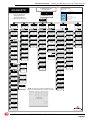
Figure 4-10: EZ-Cal Flow Chart: Diagnostics
ART_4513
SYSTEM
2A
MODE
PRESS ENTER
FOR MESSAGES
2A-1
SUPPLY
2A-2
ON/OFF
2A-3
MOTOR VOLTS
ACTUAL
2A-4
MOTOR AMPS
ACTUAL
2A-5
TEMPERATURE
OF P600
CONTROLLER
2A-6
TILT
2A-7
DIAGNOSTIC
Use in conjunction with
Diagnostic tables for
Thorough explanation
Of personalities and values
69 SERIES ELECTRIC
EZ-CAL MENU
2
DIAGNOSTICS
ENTER
TILT FILTERED
NOT USED
2A-7A
TILT LOCAL
ACTUAL IN
DEGREES LEVEL
2A-7B
TILTED
YES WHEN PAST 3
DEG.
2A-8
ENTER
ENTER
ENTER
SUPPLY
12 VOLTS DC
2A-2A
SUPPLY
CAP BANK
2A-2B
OUTRIGGERS
RETRACTED
2A-15
HEIGHT
ACTUAL IN %
2A-9
LOAD
OVERLOAD
PROTECTION ONLY
2A-10
OVERLOADED
YES or NO
2A-11
LAST MOVED
NOT USED
2A-12
ELEVATED
YES or NO
2A-13
OUTRIGGERS
EXTENDED
2A-14
SYMBOL KEY FUNCTIONS
EZ-Cal Flow Chart
Chart 2 of 2
ESC/ENTER BUTTONS
To move back and forth between
Menu and sub-menu
LEFT/RIGHT BUTTONS
Select menus and setting to be adjusted
UP/DOWN BUTTONS
Adjust setting values
PLATFORM
2B
ENTER
TRIGGER
ON/OFF
2B-1
DLD
ACTUAL
2B-2
JOYSTICK
ACTUAL DEG OF
MOVEMENT
2B-3
FWD / UP
FWD JOYSTCK
MOVEMENT
2B-4
REV / UP
REV JOYSTICK
MOVEMENT
2B-5
LEFT(STEER)
ON/OFF
2B-6
RIGHT (STEER)
ON/OFF
2B-7
GROUND
2C
UP
ON/OFF
2C-1
DOWN
ON/OFF
2C-2
ENTER
INPUTS
2D
ENTER
P7-1
12 V SUPPLY
2D-1
P7-2
BASE SELECTED
2D-2
ANALOGS
2E
ENTER
OUTPUTS
2F
CALDATE
DATE OF
CALIBRATION
2G-1
SOFTWARE
SOFTWARE
VERSION NUMBER
2G-2
MAX BATTERY
HIGHEST BATT
VOLTAGE
2G-4
BOOM GP400
ALL CIRCUITS 12V ONLY
ENTER
VALVE SUPPLY
OUT
NOT USED
2C-3
IN
NOT USED
2C-4
P7-3
UP
SELECTED
2D-3
P7-4
PLATFORM
SELECTED
2D-4
P7-7
DOWN SELECTED
2D-7
OUTRIGGERS
STATUS
2A-16
M2-6
POTENTIOMETER
2E-2A
ENTER
MATRIX
ANALOGS
UPPER CONTROL
2E-2
P4-10
REAR WHEEL
BYPASS VALVE
2F-2
P4-12
LINE
CONTACTOR
2F-3
P4-14
DOWN VALVE
2F-4
P5-2
STEER RIGHT
2F-6
P5-3
STEER LEFT
2F-7
P5-4
DRIVE FORWARD
2F-8
P5-5
DRIVE REVERSE
2F-9
P5-6
ALARM
2F-10
P5-7
HIGH TORQUE
2F-11
P5-9
HOUR METER)
2F-10
P5-10
OUTRIGGER
EXTEND VALVE
2F-11
P5-11
OUTRIGGER
RETRACT VALVE
2F-12
P6-1
OUTRIGGER
R/F UP
2F-14
P6-2
OUTRIGGER
L/F UP
2F-15
P6-3
OUTRIGGER
R/R UP
2F-16
LOG
2G
ENTER
POWERED
ACCUMULATED
HRS ON GP400
2G-3
P8-2
ANGLE
TRANSDUCER 1
2E-1A
P15-5
O/R PRESSURE
SWITCH
2D-8
P15-6
O/R PRESSURE
SWITCH
2D-9
P15-7
O/R PRESSURE
SWITCH
2D-10
P15-8
O/R PRESSURE
SWITCH
2D-11
P8-5
ANGLE
TRANSDUCER 2
CE ONLY
2E-1B
P8-6
PRESSURE
TRANSDUCER
CE ONLY
2E-1C
P8-9
TBM IN
2E-1D
P6-4
OUTRIGGER
L/R UP
2F-17
P6-5
OUTRIGGER
R/F DOWN
2F-18
P6-6
OUTRIGGER
L/F DOWN
2F-19
P6-7
OUTRIGGER
R/R DOWN
2F-21
P6-8
AMBER BEACON
2F-22
P6-10
OUTRIGGER
L/R DOWN
2F-23
NOTE: All other plug numbers that appear on the
EZ-cal but not listed here are not used on this model
TILTED MORE
YES or NO
2A-8A
ENTER
OUTRIGGERS
AUTO-RETRACT
2A-17
P4-3
REAR WHEEL
BYPASS VALVE
2F-1
P5-1
LIFT VALVE
2F-5

“4069ERT” Service and Parts ManualMarch 2014
Page 4-14
TROUBLESHOOTING -- EZ-CAL ADJUSTMENTS
EZ-C
AL
A
DJUSTMENTS
Refer to "Using the EZ-Cal Scan Tool" on page 4-10.
Adjustments are possible only in Access Level 1.
Before changing personalities, ensure that the Correct Customer and Model have been
selected in the SETUPS menu. Any changes to settings will be lost when the model or
customer is changed.
To reach ADJUSTMENTS, first access Level 1, then press --> for ADJUSTMENTS.
Press Enter, then press --> to scroll through the sub-menus.
Once the desired sub-menu is found, press Enter again, then --> to scroll through the
personalities. Press the Up or Down arrows to change the personality. Press ESC to go
back one or more levels to reach other sub-menus.
EZ-C
AL
S
ETUP
Only authorized personnel may have access to and may make changes to
personalities.
The Setups Menu is where machine and model settings may be changed. It is also the
location where calibrations are performed.
Refer to "Using the EZ-Cal Scan Tool" on page 4-10.
EZ-C
AL
D
IAGNOSTICS
The EZ-Cal Diagnostics menu provides the ability to view and test individual circuits for
irregularities. Whether diagnosing a failure or testing functions during preventative mainte-
nance, the Diagnostics Menu provides a quick view at the inputs and outputs as registered
by the GP400 Control Module in real time.
To reach DIAGNOSTICS menu from HELP;
• Press the right arrow and scroll to DIAGNOSTICS and press ENTER.
• Locate the desired sub menu and press ENTER.
• Press the right arrow to scroll through the test points.
NOTE: The ID number will not appear on the EZ-Cal display. It is shown in the Diagnostics Menu for reference only.
Press ESC to go back one level (necessary to change selection).
Page is loading ...
Page is loading ...
Page is loading ...
Page is loading ...
Page is loading ...
Page is loading ...
Page is loading ...
Page is loading ...
Page is loading ...
Page is loading ...
Page is loading ...
Page is loading ...
Page is loading ...
Page is loading ...
-
 1
1
-
 2
2
-
 3
3
-
 4
4
-
 5
5
-
 6
6
-
 7
7
-
 8
8
-
 9
9
-
 10
10
-
 11
11
-
 12
12
-
 13
13
-
 14
14
-
 15
15
-
 16
16
-
 17
17
-
 18
18
-
 19
19
-
 20
20
-
 21
21
-
 22
22
-
 23
23
-
 24
24
-
 25
25
-
 26
26
-
 27
27
-
 28
28
-
 29
29
-
 30
30
-
 31
31
-
 32
32
-
 33
33
-
 34
34


Mec 4069ERT - A92.6 Schematic Diagram
- Type
- Schematic Diagram
- This manual is also suitable for
Ask a question and I''ll find the answer in the document
Finding information in a document is now easier with AI
Related papers
-
Mec 4069ERT - CE Schematic Diagram
-
-
-
-
-
-
-
-
-
Other documents
-
Husqvarna DXR300 User manual
-
Maxon SMARTLINK® MRV Operating instructions
-
Falcon FS 108Z vario User manual
-
Terex Gyro 4020 User manual
-
Skyjack SJ9250 RT User manual
-
-
Yamaha SV12 User manual
-
Genie GS-3384 User manual
-
JLG T500J Service And Maintenance Manual
-
 Wipo 04.020.010.0129 Datasheet
