
JACOBSEN
Service
Manual
E-Plex II
Product Code: 898853, 898854
JACOBSEN
WARNING: If incorrectly used this machine can cause severe injury. Those
who use and maintain this machine should be trained in its proper use,
warned of its dangers and should read the entire manual before attempting to
set up, operate, adjust or service the machine.
GBGB
GBGB
GB
Part No. 24419G Rev 01(RJ 50 102000)


1
2
3
4
5
6
7
8
9
10
11
12
13
14
INTRODUCTION
CONTROLS
ENGINE
DRIVE CHAIN
BRAKE SYSTEM
STEERING
WHEELS & TYRES
HYDRAULICS
CHASSIS
ELECTRICAL SYSTEM
PREVENTATIVE MAINTENANCE
ATTACHMENTS
OPTIONS
MISCELLANEOUS
NOTES
INDEX
15


1
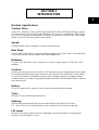
SECTION 1
INTRODUCTION
Machine Specifications
Traction Drive
Motor: G.E. 48 volt DC, shunt wound, totally enclosed 2.6 kW (at 2300 rpm) directly coupled
to a Cushman 15.67:1 ratio worm gear differential. The motor is controlled by a PMC control-
ler. There is a separately excited motor controller (Microprocessor-based), with a half bridge
design, using a Closed loop speed control system.
Speed
Cutting speed 6.4 km/h maximum. Transport Speed 12 km/h
Reel Drive
0.5hp (0.4KW) 48 Volt direct coupled, permanent magnet DC electric motor. Solid State Reel
Control Unit Current-sensing outputs with overload protection.
Batteries
8 Trojan T 105 with up to 3 hour’s operation on one full charge. Option of T 125 and T 145
batteries.
Controls
Electronic motor speed control; Lestronic II 25-amp self charger, integrated raise/lower pedal;
foot operated on/off mowing switch; manual rocker switch for reel raise/lower, rocker switch
for reel on/off selection; reel and lift actuators have overload protection; headlights; battery
condition meter; hour meter: foot pedal forward/reverse With infinite variable speed; regenera-
tive speed control.
Brakes
15 cm (6”) diameter disc brakes on each wheel, mechanically foot actuated.
Tyres
20 x 10-10, 2 ply 0.68 bar ground pressure.
Steering
380 mm steering wheel with cable to rear wheel requiring 5kg effort on concrete.
2.5 turns lock to lock, available electric power steering < 5% range loss expected.
Lift Lower
48 volt linear actuator (Warner Electric) Adjustable internal limit switches, Independently
selected , manual up down control.


9
SECTION 9
CHASSIS
New Locating
Pin
Locating Pin
To Secure In
Work
Locking
Pin Three
Positions
Cutting Units
Quick Detach Units

Cutting Unit Maintenance
The cylinder to Bottom Blade adjustment on the E-Plex is of the utmost importance.
The drag felt on the motor caused by an incorrect adjusted cylinder will greatly reduce the
performance of the machine.

10
10-1
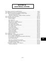
SECTION 10
ELECTRICAL SYSTEM
10A. Repair, Service Tools and Materials ............................................................. 10A-3
10B. Batteries Performance/ Charging/Maintenance........................................... .10B-5
10C. Layout Of Components(Batteries, Traction Motor) ........................................10C-7
Layout Of Components (RCU) .................................................................10C-8
Layout Of Components ( Cutting Unit Motor,Controllers)...........................10C-9
10D. Electrical Circuit Description.....................................................................10D-10
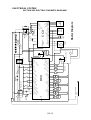
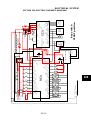
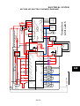
10E. Schematic diagrams..................................................................................10E-14
Master Diagram .................................................................................... 10E-14
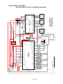
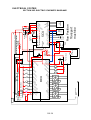
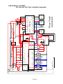
Key Switch Off ....................................................................................... 10E-15
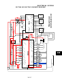
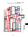
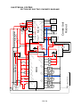
Key Switch 1st Position ........................................................................ 10E-16
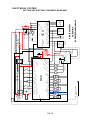
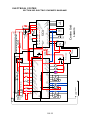
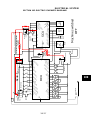
Manual Lower Switch Depressed .......................................................... 10E-17
Limit Switch Activates ........................................................................... 10E-18
Key Switch Start Position ...................................................................... 10E-19
Run Position Transport Machine ........................................................... 10E-20
Run Position Mow.................................................................................. 10E-21
CentreUnits Lowers ...............................................................................10E-22
Centre Unit Limit Switch ........................................................................ 10E-23
Raise Pedal Depressed........................................................................ 10E-24
Centre Unit Raises ................................................................................ 10E-25
Centre Unit Raised ................................................................................ 10E-26
Machine Switched Off............................................................................ 10E-27
10F. Programmer Terms.................................................................................... 10F-28
10G. Fault finding - Locating wire connections....................................................10G-30
RCU Controller voltage tests..................................................................10G-31
RCU Actuator Circuit testing (limit switches and wiring) .........................10G-34
RCU actuator motor test ........................................................................10G-35
Main Contactor output ...........................................................................10G-36
Main reel contactor/electronic throttle .....................................................10G-37
Mow speed pot testing, seat switch testing ............................................10G-38
Solenoid contactor testing .....................................................................10G-39
Curtis PMC Controller - LED Diagnosis.....................................................10G-40
Trouble shooting chart ...........................................................................10G-41


10A
ELECTRICAL SYSTEM
SECTION 10A. REPAIR, SERVICE TOOLS AND MATERIALS
10A-3
Tools required: Digital Multimeter
Jumper wires
60 amp Ammeter
Battery Tester
Cleaning Materials: Baking soda and water
Water repellent (WD40)
Other service items: Electrical insulation compound


10B
ELECTRICAL SYSTEM
SECTION 10B. BATTERIES PERFORMANCE CHARGING MAINTENANCE
10B-5
Batteries
8 x 48 Volt battery pack. Trojan T 105 T 125 or T 145 batteries, available with a removable lift out
battery pack.
Minutes @ Minutes @20 Hour Weight
Volts 25 Amps 75 Amps Rate (KGs)
Trojan T-105 6 419 115 217 28.18
Trojan T-125 6 477 132 235 30.00
Trojan T-145 6 530 145 244 32.72
Total battery pack weight = 225.44 kg minimum 261,76 kg maximum
Note: The 20 hr rate is a rate used by the U.S. to calculate battery running time at a particular amp
draw.
Performance /Charging /Maintenance
The battery performance on the E-Plex is greatly affected by the adjustment of the cutting units and
the batteries working performance will be greatly reduced. Specially by dull unsharpened cylinders,
to this end a regular maintenance program should be enforced (see cutting unit section). Tyre pres-
sures should also be checked regularly.
Before any charging procedure takes place assure that the electrolyte level in the cells, it should be
above the plates. If the electrolyte consumption is excessive it indicates one of the following:
Overcharging
High temperature operation
The battery is at the end of its service life
The battery pack is only as good as the worst battery in the pack, so take regular specific gravity
readings of all batteries. If low readings are found on any one battery try charging the battery out of
the pack and check condition. A normal reading will be between 1.250 and 1.280. If low readings
are found across the pack check that the charger is operating correctly.
Avoid the top up charge, traction battery’s life is measured in cycles every time you charge the
battery removes a cycle from its life. Remember batteries supplied are not pre-conditioned so a
period of conditioning is required.
Do not allow discharged batteries to stored for an extended period of time. Check Chart below:
Below 4 degrees C Charge every 6 months
Between 4 and 15 degrees C Charge every 2 months
Above 15 degrees C Charge once a month
It cannot be stressed enough the importance of a proper battery maintenance program especially on
Demo units.


10C
ELECTRICAL SYSTEM
SECTION 10C. LAYOUT OF COMPONENTS
10C-7
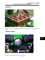
Electric’s
Eight Six Volt Trojan T105 Batteries as Standard, Showing lift out point for quick change
of pack
Traction Motor
48 Volt D.C. Motor showing sensor for speed control.

ELECTRICAL SYSTEM
SECTION 10C. LAYOUT OF COMPONENTS
10C-8

10C
ELECTRICAL SYSTEM
SECTION 10C. LAYOUT OF COMPONENTS
10C-9
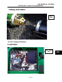
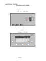
Cutting Unit Motor
0.5 H.P Cutting Unit Motor
Controllers
Motor
0.5hp
Reel Control
Unit


SECTION 10D. ELECTRICAL CIRCUITS DESCRIPTION
ELECTRICAL SYSTEM
10D-11
10D
ELECTRICAL CIRCUITS
(Use wiring diagrams with the following descriptions)
General Description
Power for the E-Plex II is supplied by eight six-volt traction batteries. The 48V DC circuit has two
separate controllers, the RCU (Reel Control Unit) for the cutting, lift and lower circuits and the SCU
(Speed Control Unit) for the traction circuit.
The traction motor is a 48V DC shunt wound motor, a speed control chip and sensor allow the
machine to be driven in the same way as hydraulic powered units.
The cutting unit motors are 48V DC motors. The cutting unit motors are protected from damage by
potted circuit breakers.
The48V DC worm drive actuators serve as lift arms, limit switches ensure that the arms can float, lift
and lower correctly.
System Description
Stage One Key Position
The machine has a Service Position this allows for service work to be carried out on the machine
without drive to the traction system.
Power is supplied to the key switch through a 12.5A circuit breaker. In the first key position the
connectors ACC and IGN are connected.
Power is supplied to the control switches. Individual function of the switches is described below.
Manual Lift/Lower
Power is fed to the manual lift/lower switch from IGN position on the key switch. To select lift the
operator pushes the switch this sends an impulse to the RCU on the lift side. Depending on the
position of the three enable switches, one two or three units can be lifted.
With the switch in the enable position an impulse is sent to the RCU. With the actuator in the lowered
position the down limit switch closed. An impulse to the RCU allows the actuator to be raised.
When fully raised the (up limit) switch closes which again sends an impulse to the RCU disengaging
the power to the actuator.
The adjustment of the limit switches is important and is covered in Section ———— of this manual.
Note: No Reel Drive is available when in the Service Position.

SECTION 10D. ELECTRICAL CIRCUITS DESCRIPTION
ELECTRICAL SYSTEM
10D-12
Stage 2 Key Position (Start)
To start the machine, the key is turned to the ST (start) position. In order to start the machine the lift/
lower pedal must be in the raised position and the operator must be sat in the seat. If either switch is
not in the correct position the RCU will not allow the machine to start.
A feed is sent from the RCU to the coil of the Traction Contactor, closing the contactor allowing a
connection to B+ on the SCU. Feeds also input the SCU at the interlock and the coil return.
From the ST position a feed is sent to the start position on the RCU which transfers control from the
manual lift/lower switch to the raise/lower foot-pedal. The Green light illuminates indicating that the
machine is ready for operation.
Transport and Mow Speed
With the Transport/Mow switch in the transport position the machine can be driven at the maximum
speed of 12km/h .The electronic throttle connected to the drive pedal sends a signal to the SCU.
The position of the throttle sets a resistance, which is sensed by the SCU, this resistance figure
changes the speed. A more detailed description can be found in the Section on the SCU later in this
manual.
Power is sent to the motor’s armature from the B+ (positive side of battery) position on the SCU.
Within the controller a connection is made from B+ to F1 the motors field coil. Return connections
are made from A2 (armature) F2 (field coil) and B- negative side of battery. These connections set
up the magnetic field, which drives the motor.
A sensor on the motor ‘again in simple terms’ monitors the speed the motor is turning. The SCU
then adjusts the voltage control according to the speed. The SCU works by switching the DC
voltage on and off (mark speed ratio). If an overrun situation occurs for example ‘descending a
slope’ the speed the motor is turning is faster than the SCU outputs are set, in this situation the motor
is turned into a generator by the SCU in a so called regenerative speed, this load slows the motor.
This braking action occurs as long as the outputs do not match the motor speed.
The sensor is a magnet and a chip, which can be found at the front of the motor.
In the mow position the switch on the control panel is switched to the mow position, a signal is sent
from the switch to the SCU. The SCU then senses the position of the mow potentiometer this
changes the resistance figure slowing the motor, by changing the mark speed ratio. At the same time
a signal is sent to the RCU from the drive motor sensor this tells the RCU that the machine is in the
mow position. It is only possible to run the reels when the machine is in the mow position.
Page is loading ...
Page is loading ...
Page is loading ...
Page is loading ...
Page is loading ...
Page is loading ...
Page is loading ...
Page is loading ...
Page is loading ...
Page is loading ...
Page is loading ...
Page is loading ...
Page is loading ...
Page is loading ...
Page is loading ...
Page is loading ...
Page is loading ...
Page is loading ...
Page is loading ...
Page is loading ...
Page is loading ...
Page is loading ...
Page is loading ...
Page is loading ...
Page is loading ...
Page is loading ...
Page is loading ...
Page is loading ...
Page is loading ...
Page is loading ...
Page is loading ...
Page is loading ...
Page is loading ...
Page is loading ...
Page is loading ...
Page is loading ...
Page is loading ...
Page is loading ...
Page is loading ...
Page is loading ...
Page is loading ...
Page is loading ...
Page is loading ...
Page is loading ...
Page is loading ...
Page is loading ...
Page is loading ...
Page is loading ...
Page is loading ...
Page is loading ...
Page is loading ...
Page is loading ...
-
 1
1
-
 2
2
-
 3
3
-
 4
4
-
 5
5
-
 6
6
-
 7
7
-
 8
8
-
 9
9
-
 10
10
-
 11
11
-
 12
12
-
 13
13
-
 14
14
-
 15
15
-
 16
16
-
 17
17
-
 18
18
-
 19
19
-
 20
20
-
 21
21
-
 22
22
-
 23
23
-
 24
24
-
 25
25
-
 26
26
-
 27
27
-
 28
28
-
 29
29
-
 30
30
-
 31
31
-
 32
32
-
 33
33
-
 34
34
-
 35
35
-
 36
36
-
 37
37
-
 38
38
-
 39
39
-
 40
40
-
 41
41
-
 42
42
-
 43
43
-
 44
44
-
 45
45
-
 46
46
-
 47
47
-
 48
48
-
 49
49
-
 50
50
-
 51
51
-
 52
52
-
 53
53
-
 54
54
-
 55
55
-
 56
56
-
 57
57
-
 58
58
-
 59
59
-
 60
60
-
 61
61
-
 62
62
-
 63
63
-
 64
64
-
 65
65
-
 66
66
-
 67
67
-
 68
68
-
 69
69
-
 70
70
-
 71
71
-
 72
72


Ransomes 24419G User manual
- Type
- User manual
- This manual is also suitable for
Ask a question and I''ll find the answer in the document
Finding information in a document is now easier with AI
Related papers
-
Ransomes 4171648 User manual
-
Ransomes 62853 Owner's manual
-
-
-
Ransomes Eclipse 322 62803 User manual
-
-
-
-
-
Ransomes 24794 Accessories Manual
Other documents
-
Actron CP7677 Specification
-
Energizer HDL33A2E User manual
-
Energizer Pro 4 User manual
-
Blaupunkt B10RD Datasheet
-
 AES e-LOOP In-ground Operating instructions
-
FSR K-10D Owner's manual
-
Blaupunkt BT 10 Operating instructions
-
GE IC3645SP4U400N3 User manual
-
Curtis 1268-5403 Pre-Installation Instructions
-
andrews HIflo Flue Damper Kit Fitting Instructions
