Page is loading ...

Riva Open Log Burning
Convector Fireboxes
16", 22", 24", 26" & 28" Standard and Low models
PM219 - Issue 1 (June 2008)
Instructions for Use,
Installation and Servicing
For use in Great Britain and Republic of Ireland.
IMPORTANT
This appliance will become hot whilst in operation, it is therefore recommended that a suitable guard should be used for the
protection of young children, the elderly or infirm. Do not attempt to burn rubbish in this appliance.
Please read these Instructions carefully before installation or use.
Keep them in a safe place for future reference and when servicing the fire.
The commissioning sheet found on page 3 of these instructions should be completed by the Installer.
This appliance has been certified for use in countries other than those stated. To install this appliance in these countries, it is essential to obtain the translated
instructions and in some cases the appliance will require modification. Contact Stovax for further information.

2
COVERING THE FOLLOWING MODELS:
8610/8611/8604/8605/8606/8607/8608/8609/8673
COMMISSIONING 27
MAINTENANCE & SERVICING 28
Annual Service 28
Removal of Flue Damper 28
SERVICE RECORDS 30
EC DECLARATION OF CONFORMITY 31
APPLIANCE COMMISSIONING CHECKLIST 3
USER INSTRUCTIONS 4
General Points 4
Using the Appliance for the first time 5
Recommended Fuels 5
Lighting the appliance 6
Running the appliance 6
Burning Tips 7
Ash Removal 8
Extended burning 9
Over-Firing 9
Chimney Fire 9
General Cleaning 9
Cleaning Glass 9
Chimney Sweeping 10
Care of Stove 10
Seasonal Use 10
Troubleshooting Tips 10
INSTALLATION INSTRUCTIONS 11
Technical Specifications 11
Standard Features 11
Packing List 11
Dimensions 12
SITE REQUIREMENTS 14
Flue & Chimney 14
Flue output positions 15
Hearth Dimensions 15
Builders Opening 16
Fire Surround Clearances 16
PRE-INSTALLATION 17
Ventilation 17
Additional Ventilation 18
INSTALLATION 19
Legal Requirements 19
Installing the Appliance 19
Fitting of fuel kits - Log 20
Fitting of fuel kits - Multi-fuel 20
Fitting of Frames 21
Removable Bottom Frame Plate 23
Fitting of Optional Flue Gather 24
Installing Cast Iron Convector 24
Fitting & Removal of Flue Damper 25
Damper Arm Adjustment 25
Fitting & Removal of Traditional Sparkguard 26
Fitting & Removal of Contemporary Steel Frame Sparkguard 26
This appliance has been approved by HETAS Ltd.

3
APPLIANCE COMMISSIONING CHECKLIST
Dealer appliance was purchased from
Name: .....................................................................................................................................................................................
Address: ..................................................................................................................................................................................
................................................................................................................................................................................................
Telephone number: ................................................................................................................................................
Essential information - MUST be completed
Date installed: .........................................................................................................................................................................
Model description: ..................................................................................................................................................................
Serial number: .......................................................................................................................................................
Installation Engineer
Company name: .....................................................................................................................................................................
Address: .................................................................................................................................................................................
...............................................................................................................................................................................................
Telephone number: ................................................................................................................................................................
Commissioning Checks (to be completed and signed)
Is flue system correct for the appliance YES NO
Flue swept and soundness test complete YES NO
Appliance sealed to opening YES NO
Smoke test completed on installed appliance YES NO
Spillage test completed YES NO
Use of appliance and operation of controls explained YES NO
Instruction book handed to customer YES NO
Signature: ....................................................................................... Print name: ...............................................................
To assist us in any guarantee claim please complete the following information:-

4
1. GENERAL POINTS
1.1 Before use of this appliance please read these
instructions fully.
1.2 All local regulations, including those referring to national
and European Standards need to be complied with when
installing the appliance.
1.3 Only use for domestic heating in accordance with these
operating instructions.
1.4 You must burn only approved fuels. Do not use with liquid
fuels or as an incinerator.
1.5 Appliance surfaces become very hot when in use. Use a
suitable fireguard if young children, elderly or infirm persons
are present.
Stovax offer firescreens, sparkguards and hearthgate systems
for protection*. Your Stovax dealer can advise you about
these products.
1.6 Do not place photographs, TV’s, paintings, porcelain or
other combustible items on the wall or near the appliance.
Exposure to hot temperatures will cause damage.
1.7 Extractor fans or cooker hoods must not be placed in the
same room or space as this can cause appliance to emit
fumes into the room.
1.8 Do not obstruct inside or outside ventilation required for
the safe use of this appliance.
1.9 Do not make unauthorised changes to the appliance.
1.10 The chimney must be swept at least once a year.
See Section 12
1.11 Do not connect, or share, the same flue or chimney
system with another appliance.
SERIAL NUMBER
This number will be required when ordering spare parts or
making any warranty claims. It is found on the Data plate.
PRODUCT:
MODEL No.
SERIAL No.
PR8001
Base Plate
1.12 To access the data plate:
If a Contemporary Steel Frame is fitted, lift the frame off,
see Installation Instructions Section 3 Fitting Of Frames.
If fitted remove multi-fuel kit or log tray before lifting out
the base plate, see Installation Instructions Section 2 Fitting
Of Fuel Kits.
•Liftoutthebaseplate,diagram1
AIR CONTROLS
Convection principle
Convector boxes convert more of the potential heat in fuel
than an open hearth.
1) Air is drawn in below the firebox
2) It is heated in the convection chambers on both sides
and below the firebox.
3) Warm air passes out into the room giving additional
radiated heat.
For Damper Controls, See Diagram 3
To operate: Move the Damper Control using the tool provided
DO NOT OPERATE WITH BARE HANDS
PR8068
Open
Close
*In the U.K: These products must conform to BS 6539,
Fireguards for use with solid fuel appliances.
If appliance is operating unattended they must conform to
BS 3248
USER INSTRUCTIONS

5
WARNING
Properly installed operated and maintained this
appliance will not emit fumes into the room.
Occasional fumes from de-ashing and refuelling may occur.
Persistent fume emission is potentially dangerous and
must not be tolerated.
If fume emission does persist:
•Opendoorsandwindowstoventilatetheroom
•Allowfiretoburnoutorsafelydisposeoffuelfromthe
appliance
•Checkforchimneyblockageandcleanifrequired
•Donotattempttorelightuntilthecauseoftheemission
has been identified and corrected
If necessary seek expert advice.
2. USING THE APPLIANCE FOR THE FIRST
TIME
2.1 To allow the appliance to settle and fixing glues and paint
to fully cure:
•Operatetheapplianceatalowoutputforfirstfewdays
2.2 Do not touch the paint during the first period of use.
2.3 During this time the appliance may give off some
unpleasant odours:
•Keeptheroomwellventilatedtoavoidabuild-upof
fumes.
3. RECOMMENDED FUELS
3.1 Wood Logs:
•Burnonlyseasonedtimberwithamoisturecontentofless
than 20%
Wood Length
Appliance Wood Length
Riva Open 16" 290mm
Riva Open 22" 440mm
Riva Open 24" 490mm
Riva Open 26" 540mm
Riva Open 28" 590mm
•Drycutwoodfor12to18monthsbeforeuse
Poor quality timber:
— Causes low combustion efficiency
— Produces harmful condensation
— Reduces effectiveness of the airwash and life of the
appliance
Do not burn construction timber, painted, impregnated
/ treated wood, manufactured board products or pallet
wood.
3.2 Solid fuel:
•Burnonlyanthraciteormanufacturedbriquettesmokeless
fuels listed as suitable for use with open heating appliances
Do not burn bituminous coal, ‘petro-coke’ or other
petroleum based fuels as this will invalidate the product
guarantee.
3.3 Fuel consumption.
As tested at nominal heat output to the requirements of
EN13229: 2001 for intermittent operation:
Description
Fuel Consumption
Kg/hour
Wood
Kg/hour
Briquette
Smokeless fuel
Riva Open 16" 3.8 1.3
Riva Open 22" 4.0 1.7
Riva Open 24" 4.2 2.1
Riva Open 26" 4.7 2.1
Riva Open 28" 5.2 2.1
3.4 For advice on suitable solid fuels:*
•Contactyourlocalapprovedcoalmerchant
A number of factors can affect the performance of the appliance.
See Section 6 for details.
*In the U.K:
•RingtheSolidFuelAssociationadvicelineon
0845 601 4406 for details
•Visittheirwebsiteatwww.solidfuel.co.uk
USER INSTRUCTIONS

6
4. LIGHTING THE APPLIANCE
4.1 For best results:
•Setdampercontrols,SeeDiagram6
PR8068
Open
Close
•Placefirelightersorpaperanddrykindlingwoodonthe
base of the firebox
•Lightthepaperorfirelighters,SeeDiagram7
•Addlargerpiecesofwood
Too many logs may smother the fire.
Do not load fuel above the log guard and the secondary
combustion inlets at the back of the firebox.
See Diagram 8
Secondary
Combustion
inlets
Log Guard
PR8069
5. RUNNING THE APPLIANCE
5.1 Burning Wood:
To burn wood it is required to fit a log box as listed:
Riva Open
Cassette
16" 22" 24" 26" 28"
Product Code Std
Product Code Low
8610/
8611
8604/
8605
8606/
8607
8608/
8609
8673
Holyrood Black 8627 8628 8629 8630
Holyrood Polished 8627P 8628P 8629P 8630P
Castle 8623 8624 8625
Portcullis 8678 8666 8667 8668 8669
Contemporary
log box
8706 8711 8721
•Woodburnsbestonabedofash
•Raketheembersevenlyoverthefirebedandopenthe
Damper control (Diagram 6) fully for a few minutes before
re-fuelling
5.2 Burn new logs at high output for a few minutes before
adjusting the Air Damper control if required. Refuel little
and often for clean, efficient burning.
5.3 Experience establishes settings to suit personal preferences.
5.4 Do not burn large amounts of fuel with the Air Damper
control closed for long periods of time. This reduces the
build up of tar and creosote in the appliance and flue
system.
5.5 When in use, burning the appliance at high output for a
short period also reduces tars and creosote.
5.6 Burning Solid fuel:
To burn smokeless fuels it is required to fit a multi-fuel kit/
cast basket as listed:
Phoenix
Cassette
Product Code Multi-fuel
kit code
Cast Basket
Code
16" 8610/8611 8705 8686
22" 8604/8605 8710 8687
24" 8606/8607
-
8687
26" 8608/8609 8720 8688
28" 8673
-
8688
USER INSTRUCTIONS

7
The multi-fuel kit is fitted as shown:
Note that this kit must only be used with the appropriate
Steel frame, Diagram 10.
PR8070
•SetPrimary Air Control, see Diagram 11
PR8071 - ClosedPR8071 - Open
PR8071 - ClosedPR8071 - Open
*Note: Frame not shown for clarity
OPEN (+)
(-) CLOSED
The Primary Air Control must be either fully open or fully
closed.
The Cast basket is fitted as shown:
PR8072
•Setairdampercontrols,SeeDiagram6
5.7 De-ash the fire bed before re-fuelling, See Section 7 Ash
Removal
•Burnnewfuelathighoutputforafewminutesbefore
adjusting the Air Damper control* to the desired setting
•Refuellittleandoftenforclean,efficientburning.
5.8 Experience establishes control settings to suit personal
preferences
5.9 Do not burn large amounts of fuel with the Air Damper
Control* on low settings for long periods of time. This
reduces the build up of tar and creosote in the appliance
and flue system.
5.10 When in use, burning the appliance at high output for a
short period also reduces tars and creosote.
5.11 You must burn only anthracite or smokeless fuels
suitable for use in open appliances.
5.12 Do not burn bituminous coal, ‘petro-coke’ or other
petroleum based fuels as this invalidates the product
guarantee.
Do not load fuel above the log guard or front of cast
baskets and the bend at the back of the firebox.
See Diagram 8
* and Primary Air Control in the case of Multi-fuel kits
6. BURNING TIPS
6.1 Fuel Quality (Wood)
Use wood with a moisture content of less than 20%.
Seasoned logs have the bark beginning to lift and peel away
and cracks radiating from the centre. They feel lighter than
fresh cut wood of a similar size and sound hollow when
struck against each other. Logs should not feel damp or
have moss and fungal growths.
Symptoms related to wet wood:
— Difficulty starting and keeping a fire burning well
— Smoke and small flames
— Rapid creosote build-up in the chimney
— Low heat output
— Short burn times, excessive fuel consumption and
blue/grey smoke from the chimney
•Burn at high output for a short period to avoid large
build-ups of tars and creosote within the appliance and the
flue system
•Use Stovax Protector chimney cleaner to reduce this
problem
6.2 Fuel Quality (Solid Fuel)
•Use recommended solid fuels approved for use with open
appliances.
Symptoms related to unsuitable fuels include:
— Difficulty starting and keeping a fire burning well
USER INSTRUCTIONS

8
— Smoke and small flames
— Short life span for grate
6.3 Flue Draught
The chimney has two main functions:
1) To safely remove the smoke, gases and fumes from the
house.
2) To provide a sufficient amount of draught (suction) in the
appliance ensuring the fire keeps burning.
Draught is caused by the rising hot air in the chimney when
the appliance is lit.
Symptoms of poor performance related to flue draught
include:
— Excessive fuel consumption (high flue draught)
— Poor burning control, overheating (high flue draught)
— Wind noise from air controls (high flue draught)
— Difficulty getting a fire going and keeping it burning well
(low flue draught)
— Low heat output (low flue draught)
— Smoke entering room when doors opened (low flue
draught)
The construction, position, size and height of the chimney
all affect the performance of the flue draught.
Other factors effecting the flue draught include:
— Trees or other buildings nearby causing turbulence
— High and gusty winds
— Outside temperature
— Outside weather conditions
— Incorrect additional ventilation to building
— Blocked flue / chimney
For advice on the correction of persistent flue problems
consult a qualified solid fuel heating engineer before
continuing to use the appliance.
6.54 Weather conditions
The weather conditions outside the building can effect the
burning performance of the appliance. These could include:
Weather Conditions Problem Effect
Windy days
Buildings/Obstacles
cause turbulent air
around chimney.
Smoky Appliance
Calm days
Oversized Chimney. Smoky Appliance
Damp / Rainy days
Flue temperature
not hot enough.
Rain water inside
chimney.
Lighting and
burning problems
To reduce these problems:
•Usegoodqualitykindlingwoodtostartthefire
•Burninitiallyatahightemperatureforashortperiod
•Fitaraincowltothechimney
Your installer should advise you on possible solutions.
If the appliance emits smoke into the room continuously:
•Allowtheappliancetogoout
•Ventilatetheroomtoclearthefumes
Do not re-light the appliance until the problem is solved.
7. ASH REMOVAL
Do not allow ash to build up in the appliance as it will
not burn properly and may cause damage.
7.1 Wood:
Regular cleaning:
•De-ashatleastonceaweekbyremovingashfromthelog
box whilst located in the appliance
•Leaveathinlayerofashtostartthenewfireon
Thorough cleaning:
•RemovetheLogbar/frontbyliftingvertically
Where a Steel frame is fitted the removable bottom frame
plate must be removed prior to lifting out the log box,
Installation Instructions 3A.
•LifttheLogboxabovethebottomlipoftheframe
opening
•Cleanthelogboxandanyashontheappliancebase
plate
PR8073
Log Bar
Log Box
7.2 Multi-fuel:
De-ash the appliance before filling with new fuel. Do not
allow ash to build up on the underside of the grate as this
can cause premature failure.
•Riddle,withapoker,SeeDiagram15
USER INSTRUCTIONS

PR8074
Poker
7.3 Remove components carefully. Heat can remain long after
use, See Diagram 16
PR8076PR8075
Multi-fuel Kit Cast Basket
Ashpan
Ashpan
Grate
Damper/
Multi-fuel
tool
Where a steel frame is fitted on the multi-fuel kit version:
•Removethelogbarandbottomframeplatebefore
removing the grates (Using the tool supplied) and Multi-fuel
box ashpan, see Installation Section 2 & 3
Once the bottom frame plate is removed access can be
gained to ash build up on the base plate with a vacuum
cleaner
7.4 Use gloves, or place the ash into a Stovax Ash Caddy
(Stovax Part No. 4227)
7.5 Do not place hot ash in a bin made from plastic or any
other combustible material.
8. EXTENDED BURNING
8.1 It is possible to lengthen the re-fuelling period.
In order to do this:
•De-ashpriortorefuelling
•SetAirDampercontrol(Primaryifmulti-fuelkitfitted)to
low combustion setting
•Usesmokelessfuelorsmall,thicklogsdependingonfuel
desired
9. OVER-FIRING
9.1 Do not over-fill with fuel or use at maximum output for
long periods or over-firing can occur. If the flue pipe, flue
collar or top plate glow red the appliance is over-firing:
•Close the Air Damper (Primary if multi-fuel kit fitted)
control to reduce the output
9.2 Over-firing can cause permanent damage to the appliance.
10. CHIMNEY FIRE
10.1 If a chimney fire occurs:
•Shut all Air Damper and Multi-fuel controls immediately
•Evacuate the building
•Call the fire brigade
•Do not re-enter the building until it is confirmed safe
10.2 Do not use the appliance after a chimney fire until:
a) It has been inspected by a registered installer,
confirming the appliance is safe to use*
b) The chimney system inspected and swept by a chimney
sweep, confirming the system is structurally sound and free
from obstruction before re-use.**
c) It is repaired as required before re-use. Use only
genuine Stovax replacement parts to keep your appliance in
safe and efficient working order.
11. GENERAL CLEANING
11.1 Allow appliance to cool thoroughly to avoid risk of burns:
•Cleanregularly,accordingtothelevelofuse
•Giveattentiontothedampersystem,fluewaysand
removing ash
Regular cleaning and maintenance will help give many years
of safe use.
•CleanmattblackappliancesusingStovaxCollodialblack
or Stovax Grate Polish
To refresh painted finishes use Stovax Thermolac paint.
•Cleanfinishesusingwarmsoapywaterandasoftclean
cloth
†
•Donotuseaerosolspraysnearanoperatingappliance
Wipe dry with a soft clean cloth
†
before re-lighting. Do not
leave unit without drying, as this may cause rust.
Do not use abrasive cleaner or cleaning pads.
9
USER INSTRUCTIONS
In the U.K:
* registered with HETAS (GB only)/INFO (Republic of
Ireland only)
** This should be done by a NACS registered (UK only)/
INFO registered (Eire only) chimney sweep, who will issue
you with a certificate.
† Note: It is recommended to use a lint free cloth when cleaning
this appliance

10
13. CHIMNEY SWEEPING
13.1 To maintain safe and efficient use of the appliance the
chimney/flue must be inspected and swept at least once a
year by a qualified chimney sweep.*
If the appliance is used continuously throughout the year
or it is used to burn wood or smokeless fuel, more frequent
sweeping is recommended.
The best time to have the chimney swept is at the start of
the heating season.
The above applies even if burning smokeless fuels.
13.2 The chimney, any connecting flue pipe and the appliance
flue ways if incorporated, must be regularly cleaned.
13.3 Ensure adequate access to cleaning doors where it is not
possible to sweep through the chimney.
13.4 If the appliance is believe to have previously served an
open fire the chimney must be swept a second time within
a month of regular use after installation.
14. CARE OF STOVE
Stovax has a range of cleaning and maintenance products and
accessories to keep your appliance in good working condition.
Your Stovax retailer can provide full details but here is a brief list of
useful items:
Product Code Description
3047 Extra long matches
5039 Gas lighter
4052 Log basket
3048 Wood sling - for easy carrying of logs
3016 Log tongs
4027 Extra long protective gloves
5038 Hearthgate - 5 section (for areas 1780x610mm
5044 Hearthgate - 7 section (for areas 1780x405mm)
4227 Ash caddy - 382x102x306mm
4228 Ash caddy - 446x102x306mm
4229 Ash caddy - 382x102x459mm
4230 Ash caddy - 637x127x408mm
4231 Ash caddy - 306x178x459mm
2091 Ashclean vacuum cleaner attachment
4232 Steel brush
Your retailer can provide genuine spare parts when required. An
annual service by a competent engineer is recommended to keep
your appliance in best possible condition.
15. SEASONAL USE
15.1 Clean and service the appliance if it is not used during the
warmer periods of the year as detailed in the Maintenance
and Servicing section
15.2 Set the Air Damper control 50% open to keep the
appliance ventilated and stop the build-up of any moisture
inside.
15.3 Before re-lighting the appliance:
•Clear any debris that may have accumulated
•Check the flue is clear of any blockages
16. TROUBLESHOOTING TIPS
16.1 Appliance is producing tar:
This is identified by:
•Averystrongpungentsmellshortlyaftertheapplianceis
lit and heats up
•Thick,brownandstickytaroozesfromthepipejoints
This is caused by burning damp wood and burning your
appliance at too low a temperature;
•Usewellseasonedwoodandoperatetheapplianceinthe
ideal temperature range
Tar is a major cause of chimney fires - if you experience
problems with tar build up consult a chimney sweep before
continued use of your appliance.
USER INSTRUCTIONS
In the U.K:
* This should be done by a NACS registered (UK only)/
INFO registered (Eire only) chimney sweep, who will issue
you with a certificate.

RIVA OPEN
TECHNICAL SPECIFICATION
1. STANDARD FEATURES
•DamperControl
•Primaryair(undergrateairforfullmulti-fueluse)*
* Multi-fuel kits 8705, 8710, 8720 only
2. PACKING LIST
•Instructions
•Guaranteecard
•Pairofgloves
•Damper/Multi-fuelgrateTool
•Poker
Model
Nominal Heat Output
Wood kW
4 6.5 8 9 10
Solid Fuel kW
3 4 5 5 5
Flue Draught at Nominal Heat All Fuels
mm
1.25 1.25 1.25 1.25 1.25
inch Wg
0.05 0.05 0.05 0.05 0.05
Flue Gas Mass Flow
Wood g/s
39.1 45.0 52.8 53.0 54.1
Solid Fuel g/s
27.8 30.0 75.1 45.0 49.5
Flue Gas Temperature at Spigot/Socket
Wood °C
200 155 165 180 220
Solid Fuel °C
110 125 120 150 150
Flue Outlet Size
mm
2x(120x102) 3x(105x105) 3x(122x105) 3x(138x105) 3x(138x105)
inch
2x(4
3
/
4
x4) 3x(4
1
/
8
x4
1
/
8
) 3x(4
13
/
16
x4
1
/
8
) 3x(5
7
/
16
x4
1
/
8
) 3x(5
7
/
16
x4
1
/
8
)
Weight Std kg 62 83 86 89 97
Low kg 59 76 81 86 -
Recommended Fuel
Wood Seasoned wood (less than 20% moisture content)
Solid Fuel
Briquette smokeless fuel suitable for open appliances
(Homefire - Supertherm)
As tested to the requirements of EN 13229:2001 for intermittent operation
16" Riva
Open
22" Riva
Open
24" Riva
Open
26" Riva
Open
28" Riva
Open
11

TECHNICAL SPECIFICATION
16" Low 22" Low 24" Low 26" Low 28"
A 474 474 624 624 674 674 724 724 774
B 592 542 652 592 652 592 652 592 652
C 348 348 348 348 348 348 348 348 348
D 550 500 610 550 610 550 610 550 610
E 400 400 550 550 600 600 650 650 700
F 489 489 639 639 689 689 739 739 789
G 595 545 655 595 655 595 655 595 655
H 16 16 16 16 16 16 16 16 16
J 481 - - - - - - - -
K 595 - - - - - - - -
L 32 - - - - - - - -
M Square - - 765 - - - 865 - -
M Rectangular 850 - 1280 - - - 1380 - -
N Square - - 700 - - - 800 - -
N Rectangular 637 - 700 - - - 720 - -
P 33 - 33 - - - 33 - -
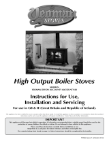
RIVA OPEN DIMENSIONS
12
PR8100
A
B
C
E
D

13
16" 22" 24" 26" 28"
Profil Brass -
standard height
8633 8635 8637 8639 8626
Profil Brass -
low lintel
8674 8636 8638 8640 -
Profil Brushed
Stainless -
standard height
8633BS 8635BS 8637BS 8639 8626BS
Profil Brushed
Stainless -
low lintel
8674BS 8636BS 8638BS 8640BS -
16" 22" 24" 26" 28"
Steel Frame -
Rectangular
8730 8732 - 8736 -
Steel Frame -
Frame
- 8733 - 8737 -
16" 22" 24" 26" 28"
Arts Frame 8700 - - - -
RIVA OPEN DIMENSIONS
TECHNICAL SPECIFICATION
PROFIL
STEEL
ARTS
PR8100
G
F
H
J
L
P
M SQUARE/RECTANGULAR
PROFIL ARTS
STEEL SQUARE/RECTANGULAR
N
SQUARE/RECTANGULAR
K

14
1. FLUE OR CHIMNEY
1.1 The flue or chimney system must be in good condition.
It must be inspected by a competent person and passed for
use with the appliance before installation
Products of combustion entering the room can cause
serious health risks.
1.2 You must check the following:
— The construction of the masonry chimneys, flue block
chimneys and connecting flue pipe system must meet the
requirements of the Building Regulations†
— A flexible flue liner system can be used if certified for
use with solid fuel systems and installation complies with
manufacturer’s instructions and Building Regulations.
The flue liner must be replaced when an appliance is
replaced unless proven to be recently installed and in good
condition.
— If it is necessary to fit a register plate it must conform to
the Building Regulations†
— The minimum height of the flue or chimney must
be 4.5m from the hearth to the top of the flue, with no
horizontal sections, a maximum of 4 bends with angles of
less than 45 degrees
— Enure the connecting flue pipe is kept a suitable
distance from any combustible material and does not form
part of the supporting structure of the building
— Make provision to remove the appliance without the
need to dismantle the chimney
— Any existing flue must be confirmed as suitable for the
new intended use as defined in the Building Regulations
— The flue or chimney systems must be inspected and
swept to confirm the system is structurally sound and free
from obstructions**
— If the appliance is believe to have previously served an
open fire the chimney must be swept a second time within
a month of regular use after installation to clear any soots
falls that may occurred due to difference in combustion
levels.
— The flue exit from the building must comply with local
building control rules.†
— Do not connect or share the flue or chimney system
with another heating appliance
1.3 Do not connect to systems containing large voids or over
230mm square.
1.4 You must provide suitable access to enable the collection
and removal of debris.
1.5 You must sweep and inspect the flue when the appliance is
installed.
1.6 You must check the flue draught with all windows and
doors closed and any extraction fans in this or adjoining
rooms running at maximum speed. (See next section for
additional ventilation requirements)
Max. Draught = 2.0mm Wg
Min. Draught = 1.0mm Wg
In the U.K:
*BS 6461: Part 1, and the requirements of Building
Regulations
**This should be done by a NACS registered (UK only)/
INFO registered (Eire only) chimney sweep, who will issue
you with a certificate.
† Building Regulations Document J
Flue Plate:
Where a hearth, fireplace, flue or chimney is provided
or extended (including cases where a flue is provided
as part of refurbishment work), information essential
to the correct appliance and use of these should be
permanently posted in the building, to meet Requirement
J4 of the Building Regulations (England and Wales), F3.12
(Scotland).
† Building Regulations Document J
Additional:
A new factory made system that complies to EN 1856; Part 1
can be used providing installation is to the requirements of:
i) BS 7566 Parts 1 -4
ii) the manufacturer's instructions
iii) Building Regulations.
For a guide containing information on Chimneys and Flues
contact:
The British Flue & Chimney Manufacturers’ Association,
FETA
2 Waltham Court
Milley Lane
Hare Hatch
Reading
Berkshire RG10 9TH
Tel: 0118 9403416 e-mail: [email protected]
SITE REQUIREMENTS

SITE REQUIREMENTS
15
3.1 The appliance must stand on a non-combustible
constructional hearth which is at least 125mm thick with
the minimum dimensions as shown in diagram. If it is to be
fitted in a raised setting consideration may need to be given
to extending the depth of the hearth to safely containing
any falling logs or embers.
3.2 The building must have a suitable load-bearing capacity for
the hearth and appliance.
•Consultastructuralengineerforadvicebefore
proceeding
3.3 When fitting into an existing hearth check:
•Thattheappliancecomplieswithcurrentconstruction
regulations and is at least the minimum sizes shown
3.4 If there is no existing fireplace or chimney it is possible to
construct a suitable non-combustible housing and hearth
setting. The flue must be installed in accordance with all
local and national regulations and current rules in force.
•Checkifaddinganewchimneytoyourpropertyrequires
planning permission
3.5 Some houses are built using a timber frame construction
with high levels of thermal insulation. Isolate the appliance
from combustible materials, and provide sufficient
ventilation to maintain the heating efficiency.
3. MINIMUM DIMENSIONS - HEARTH
Dimension A
16"
720
22"
870
24"
920
26"
970
28"
1020
1
150
150
225
500
A
Superimposed Hearth
(or area to be free of
combustible material)
Constructional
Hearth
Position On Roof Minimum Clearances
A
On ridge or within 600mm 600mm above ridge
B
Elsewhere on roof 2300mm horizontally from roof surface and:
a) 1000mm above highest point of flue exit from roof or b) as high as the ridge
C
On pitched, within 2300mm horizontally to
openable window, dormer
1000mm above top of opening
D
Within 2300mm of another building 600mm above top of building
2. FLUE OUTLET POSITIONS
150mm
max
Vertical
Measurement
Terminal
Insulation
Flue
Horizontal
Measurement
Adjacent
Building
The vertical measurement is the lowest from either the
point of discharge or 150mm above insulation.
IMPORTANT: Seek specialist
advice if installing in a dwelling
with a thatched roof

SITE REQUIREMENTS
16
4. BUILDERS OPENING
To make installation easier make the opening larger than
the minimum requirements where possible.
B
A
FRONT
C
Appliance Dim A Dim B Dim C
16" 420 560 360
22" 570 620 360
24" 620 620 360
26" 670 620 360
28" 720 620 360
Appliance Dim A Dim B Dim C
16" 420 510 360
22" 570 560 360
24" 620 560 360
26" 670 560 360
Standard Height
Low Lintel
Many fireplace openings have a supporting lintel. Remove
the covering plaster to identify it's position before starting any
constructive work. Do not remove constructional lintels without
making provision to support the remaining structure of the
building.
The appliance must not form any part of the supporting
structure.
4.1 The chimney/flue must have a sealed connection to the
appliance flue spigot.
4.2 The structure of the builders opening will reach high
temperatures. Use insulating blockwork to reduce the heat
transfer to the external walls, in particular the area of the
chimney breast above the opening.
4.3 Take care when finishing the chimney breast and
surrounding area. The conducted and convected heat
emitted by the appliance could be high enough to crack
normal plaster. Use a high temperature plaster, or face
the area with a suitable high temperature plasterboard.
New plaster should be fully dried before the appliance is
used, or cracking could occur.
If you are in any doubt about your ability to produce a
safe opening contact your Stovax dealer for professional
advice.
5. FIRE SURROUND CLEARANCES
If the appliance is to be fitted with a fire surround, use
the minimum clearances, see Diagram below, between
any point of the appliance and any combustible material.
Stovax produce a selection of surrounds and details can be
obtained from your local supplier.
150mm
300mm
150mm
PR8105
5.1 We recommend you obtain expert advice before
proceeding with work of this nature.
5.2 Some finishes may discolour with heat and some lower
quality products may distort, or crack, when in use.
If stone / granite / marble or any other natural material
is used to construct the fire surround, or any part of it,
provision should be made for expansion and movement
of the parts due to heating and cooling.
If you are in any doubt about the installation
requirements, or suitablity of fire surrounds contact your
Stovax dealer.
5.3 All fire surrounds should be suitable for use with solid fuel
heating products.

PRE-INSTALLATION CHECKS
Model
Flue/Chimney Size
Without liner system (round)
minimum dimension (diameter.)
mm 200 200 200 200 200
inch 8 8 8 8 8
Without liner system (square)
minimum dimension
mm 185 185 185 185 185
inch 7 1/4 7 1/4 7 1/4 7 1/4 7 1/4
Liner or factory made system
(diameter.)
installed in accordance with manufacturers instructions
mm 200 200 200 200 200
inch 8 8 8 8 8
Do not connect to systems containing large voids or over 9" (230mm) square/round
Flue/Chimney
minimum height*
All Products
m 4.5 4.5 4.5 4.5 4.5
feet 15 15 15 15 15
* When measured from the top of the appliance to the top of the flue, with no horizontal sections
and a maximum of 4 bends with angles of less than 45°
16" Riva
Open
22" Riva
Open
24" Riva
Open
26" Riva
Open
28" Riva
Open
17
1.1 This appliance requires ventilation to supply combustion air.
Any room containing the appliance must have a permanent
air vent opening with a total free area of at least 550mm
2
per kW of appliance rated output above 5kW.
1.2 Increase air supply provisions where a room contains
multiple appliances.
1.3 If vents open into adjoining rooms or spaces there must be
an air vent of at least the same size direct to the outside.
1.4 Permanent air vents should be non-adjustable and
positioned where they are unlikely to become blocked.
1.5 Site the vents where cold draught is unlikely to cause
discomfort. This can be avoided by placing vents near
ceilings or close to the appliance, see Diagram opposite.
1. VENTILATION

2.2 Extractor fans or cooker hoods should not be placed in the
same room or space as the appliance.
2.3 If any of these checks reveal problems do not proceed
with the fitting of the appliance until they have been
rectified.
2.1 Open appliances require additional ventilation to comply
with the requirements of the Building Regulations. This
should be provided using a permanently open air vent, of
the size listed, which is positioned so that it is not liable to
be blocked both inside and outside the building.
Model
Additional Ventilation
mm
2
14400 16538 19215 21735 21735
cm
2
144 165 192 217 217
in2
22.32 25.63 29.78 33.69 33.69
16" Riva
Open
22" Riva
Open
24" Riva
Open
26" Riva
Open
28" Riva
Open
2. ADDITIONAL VENTILATION
PRE-INSTALLATION CHECKS
18

LEGAL REQUIREMENTS
Before installation of this product please read these
instructions fully.
It is very important to understand the requirements of the national
Building Regulations* and standards**, along with any local
regulations and working practices that may apply. Should any
conflict occur between these instructions and these regulations
then the regulations must apply.
Your local Building Control Office can advise regarding the
requirements of the regulations.
The appliance must be fitted by a registered installer†, or approved
by your local building control officer.
Works must be carried out with care to meet the requirements of
Health and Safety and comply with the Health and Safety rules,
and any new regulations introduced during the lifetime of these
instructions. Particular attention should be drawn to:
•Handling: The appliance is heavy. Adequate facilities
must be available for loading, unloading and site handling.
•Fire Cement: Some fire cement is caustic and must not
come into contact with the skin. Protective gloves must be
worn. Wash hands thoroughly with plenty of water after
contact with skin.
•Asbestos: This appliance contains no asbestos. If there
is the possibility of disturbing any asbestos in the course of
installation seek specialist guidance and use appropriate
equipment.
•Metal Parts: Take care when installing or servicing the
appliance to avoid personal injury.
A faulty installation can cause danger to the inhabitants and
structure of the building.
For users of this appliance:
Your building insurance company may require you to inform them
that you have installed a new heating appliance. Check that your
cover is still valid after installing the appliance.
1. INSTALLING THE APPLIANCE
To make the fitting of the appliance easier, gain better access to
the flue connection and protect paintwork from damage. The base
plate may be removed on the appliance, Diagram 3.
1.1 To get the best output from the appliance the rear and side
must be well insulated, Diagram 1.
1
Additional insulation may be required if the recess sizes are
larger than shown.
1.2 Any non-combustible insulation will be acceptable such
as vermiculite or Perlite. Poor insulators, such as lime or
rubble, should only be used after a good insulator has been
installed around the firebox.
1.3 Decide whether the insulation is to be positioned before
or after the installation of the firebox (vermiculite can be
poured through the flue-ways into the recess after the
appliance has been installed).
• Lifttheapplianceintoposition,Diagram2
• Pushbackuntilthefireboxflangessitflatagainstthe
fireplace opening
2
Insulation
Infill
Plan
Firebox Flange
Fireplace
Opening
1.4 No fixing is required but if the front face of the opening is
rough, such as natural stone, it will be necessary to seal the
flanges using fire cement
1.5 Ensure the box sits squarely and does not rock in any
direction.
1.6 Install the base plate by sliding it over the side and rear
ledges, Diagram 3
INSTALLATION INSTRUCTIONS
19
In the U.K:
*•EnglandandWales–DocumentJ/Scotland-PartF,
Building Regulations, 1997 Technical Guidance Document
J Heat Producing Appliances (Republic of Ireland only)
**•Registeredbody:HETAS(GBonly)/INFO(Eire)

3
PR8079
2A. FITTING OF FUEL KITS - LOG
2.1 Install the relevant fuel box.
4
PR8080
2.2 Fit the Log Retainer (Holyrood, Castle, Portcullis),
Diagram 5.
Note: the Holyrood retainer has a specially curved log-
burning tray.
5
PR8081
Back of Log
Retainer
Retaining clips
• Fit retaining clips over the front lip of Log Box
2.3 Fit the Contemporary Log Box, Diagram 6
INSTALLATION INSTRUCTIONS
20
• Liftoverframe
6
PR8073
2.4 Fit the Contemporary Log Bar, Diagram 7
• Slideintochannelsinfrontofthelogbox
The removable frame plate is not shown for clarity but must
be in place before the Log Bar is fitted, See Section 3A.
7
PR8082
2B. FITTING OF FUEL KITS -
MULTI-FUEL
2.5 Slide the Cast Basket and Ashpan on to the base plate,
diagram 8
8
PR8083
/