Page is loading ...

MultiLink ML1600/ML2400
Ethernet Communications Switch
Quickstart Guide
Firmware Revision 2.1x
Manual P/N: 1601-9026-A2
Manual Order Code: GEK-113393A
Copyright © 2008 GE Multilin
GE Multilin
215 Anderson Avenue, Markham, Ontario
Canada L6E 1B3
Tel: (905) 294-6222 Fax: (905) 201-2098
Internet: http://www.GEmultilin.com
*1601-0220-A2*
I
ISO9001:2000
G
E
M
U
L
T
I
L
I
N
R
E
G
I
S
T
E
R
E
D
GE Multilin's Quality
Management System is
registered to ISO9001:2000
QMI # 005094
UL # A3775
GE Consumer & Industrial
Multilin

These instructions do not purport to cover all details or variations in equipment nor provide
for every possible contingency to be met in connection with installation, operation, or
maintenance. Should further information be desired or should particular problems arise
which are not covered sufficiently for the purchaser’s purpose, the matter should be referred
to the General Electric Company.
To the extent required the products described herein meet applicable ANSI, IEEE, and NEMA
standards; but no such assurance is given with respect to local codes and ordinances
because they vary greatly.
© 2008 GE Multilin Incorporated. All rights reserved.
GE Multilin Multilink ML1600/2400 Quickstart Guide for revision 2.1.x.
Multilink ML1600/2400 is a registered trademark of GE Multilin Inc.
The contents of this manual are the property of GE Multilin Inc. This documentation is
furnished on license and may not be reproduced in whole or in part without the permission
of GE Multilin. The content of this manual is for informational use only and is subject to
change without notice.
Part numbers contained in this manual are subject to change without notice, and should
therefore be verified by GE Multilin before ordering.
Part number: 1601-9026-A2 (March 2008)

TABLE OF CONTENTS
MULTILINK ML1600/2400 ETHERNET COMMUNICATIONS SWITCH – QUICKSTART GUIDE TOC–I
Table of Contents
INTRODUCTION TO TWISTED PAIR AND FIBER OPTIC ETHERNET LANS ............QS-1
E
THERNET PHYSICAL LAYER: TWISTED PAIR COPPER VS FIBER OPTIC ........................ QS-1
Twisted Pair copper cable ............................................................................. QS-2
Fiber ......................................................................................................................... QS-2
SUPPORTED NETWORK TOPOLOGIES ................................................................................ QS-3
Star Architecture ................................................................................................ QS-3
Mesh Architecture ............................................................................................. QS-3
Ring Architecture ............................................................................................... QS-3
10BASE T AND 100BASET MEDIA ..................................................................................QS-4
Unshielded Twisted Pair cable: ................................................................... QS-4
Ethernet: Unshielded Twisted Pair ............................................................. QS-4
HUBS AND SWITCHES ......................................................................................................QS-7
F
IBER OPTIC ETHERNET: ..................................................................................................... QS-7
Wavelengths of light ........................................................................................ QS-7
SINGLE AND MULTI-MODE CABLE ..................................................................................... QS-8
Fiber Cable Cross Section and Physical Specifications ................... QS-8
Single mode fiber - Less attenuation per unit distance .................. QS-9
OPTICAL POWER BUDGET ..............................................................................................QS-10
A
SSIGNING AN IP ADDRESS TO THE MULTILIN SWITCH ................................................. QS-11
A
SSIGNING A STATIC IP ADDRESS TO A PERSONNEL COMPUTER .................................. QS-18
C
ONFIGURING THE SWITCH PORTS FOR UR REDUNDANT OPERATION ........................ QS-23
TAGGED VLAN’S .................................................................................................................QS-27
Background: ......................................................................................................... QS-27
CONFIGURING TAGGED VLANS ........................................................................................ QS-28
Configuring a VLAN within the switch ..................................................... QS-28
CONFIGURING THE MULTILINK SWITCH FOR RING ONLY MODE .................................. QS-38
ML1600/2400 FIRMWARE UPDATES ............................................................................QS-49
U
PDATING MULTILINK FIRMWARE .................................................................................... QS-49
S
ELECTING THE PROPER VERSION .................................................................................... QS-49
U
PGRADING USING A SERIAL CONNECTION- COMMAND LINE INTERFACE ................ QS-49
U
PDATING USING THE ENERVISTA WEB INTERFACE SOFTWARE ................................. QS-54
Using FTP ............................................................................................................... QS-55
Using TFTP ............................................................................................................. QS-56

TOC–II MULTILINK ML1600/2400 ETHERNET COMMUNICATIONS SWITCH – QUICKSTART GUIDE
TABLE OF CONTENTS

MULTILINK ML1600/2400 ETHERNET COMMUNICATIONS SWITCH – QUICKSTART GUIDE QS–1
Multilink ML1600/2400
Ethernet Communications Switch
Quick Start Guide
GE Consumer & Industrial
Multilin
Quick Start Guide
QS.1 Introduction to Twisted Pair and Fiber Optic Ethernet
LANs
This section will provide a brief review of modern Ethernet media before covering the steps
to correctly configure the Multilink switch for typical protective relaying applications. For
this discussion the range of IP addresses that will be used are within the range of
3.94.247.1 to 3.94.247.254 using a subnet mask of 255.255.255.0. This same range of
addresses can be used for testing purposes but you should contact your IT support group
for a valid range of addresses to be used for your particular application.
QS.1.1 Ethernet Physical Layer: Twisted Pair Copper vs Fiber Optic
Today, the two most popular physical layer standards for Ethernet are twisted pair copper
cable and fiber optic cable. Twisted pair copper is easier to terminate, has lower
installation costs but is susceptible to electrical noise and a single run of twisted pair cable
is distance limited.
Fiber optic media typically is able to be applied over much longer distances, is immune to
electrical noise and while being more difficult to terminate the availability of per-
fabricated cables has reduced the complexity of the installation within the substation
dramatically.

QS–2 MULTILINK ML1600/2400 ETHERNET COMMUNICATIONS SWITCH – QUICKSTART GUIDE
QUICK START GUIDE
Twisted Pair copper cable
• Easy to Terminate
• Low installation costs
• Susceptible to noise interference
• Limited by 100m distance
• Either shielded or unshielded (UTP)
Fiber
• Longer distances possible, limited only by attenuation
• Immune to electrical noise
• More difficult termination and splicing
• Slightly higher cost for cable
• Two categories:
• multi-mode
• single-mode

QUICK START GUIDE
MULTILINK ML1600/2400 ETHERNET COMMUNICATIONS SWITCH – QUICKSTART GUIDE QS–3
QS.1.2 Supported Network Topologies
With either media supported topologies include: star, mesh and ring. The port that
connects one switch to another is often called the uplink port and with many switches the
uplink port can operate at much higher baud rates than the standard ports. The link
formed by the connection of of several switches higher speed uplink ports is often referred
to as a backbone.
Star Architecture
• Single Point of failure before loss of communications
• Additional Ethernet switches Required
• Network Recovery in approximately 6 ms per Ethernet switch
Mesh Architecture
• Multiple Points of failure required before loss of communications
• Additional Fiber Cables required
Ring Architecture
• Full Network Redundancy
• Allows for Fastest Network Recovery
*
• Most Cost Effective Solution
Ring
Mesh
Star
* RO mode has typical recovery time of ≤ 5 ms/hop.

QS–4 MULTILINK ML1600/2400 ETHERNET COMMUNICATIONS SWITCH – QUICKSTART GUIDE
QUICK START GUIDE
QS.2 10BASE T and 100BaseT Media
10 Base T and 100 Base T are the two most common twisted pair copper media standards.
There are also several popular fiber optic media standards which we will review later in
this section. With respect to 10 or 100 Base T, the 10 or 100 designation indicates a baud
rate of either 10 or 100 megabits per second. Base stands for baseband while the T stands
for "twisted pair."
Since many twisted pair interfaces can work at either baud rate, the designation 10/100
Base T has evolved to show this capability. The cable can be ether unshielded twisted pair
(UTP) or shielded twisted pair (STP).
We recommend category 5e UTP for applications of up to 100 Mbs
Unshielded Twisted Pair cable:
• Category 1: Used for telephone communications; not suitable for transmitting
data.
• Category 2: Capable of transmitting data at speeds of up to 4 Mbps.
• Category 3: Can be used in 10BASE-T networks; can transmit data at speeds up to
10 Mbps.
• Category 4: Used in Token Ring networks; can transmit data at speeds up to 16
Mbps.
• Category 5: Capable of transmitting data at speeds up to 100 Mbps.
• Category 5e*: Used in networks running at speeds up to 1000 Mbps (1 Gbps).
• Category 6: Consists of four pairs of 24-gauge copper wires, which can transmit
data at speeds of up to 1000 Mbps.
* Recommended
Ethernet: Unshielded Twisted Pair
:
100 metres max.

QUICK START GUIDE
MULTILINK ML1600/2400 ETHERNET COMMUNICATIONS SWITCH – QUICKSTART GUIDE QS–5
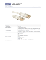
FIGURE QS–1: Pin Layout for a RJ45 Ethernet Straight-through Cable
The cable itself consists of four pairs of wires terminated in RJ45 connectors. The
maximum permitted cable length is 100 meters. The cable pin connections can be one of
two configurations. The first is called a "straight-through" cable and the second is called
either a "crossover" or a "patch" cable. Whether the cable is straight-through or crossover
as per standard* each of the wires within the cable has the following color code:
For the first twisted wire pair or wire pair #1: one wire is White with Blue bands while the
other wire is Blue.
For the second twisted wire pair one wire is White with orange bands while the other wire
is orange.
The third twisted wire pair #3 consists of a white wire with green bands and a second wire
that is green.
The final wire pair, wire pair #4 consists of a white wire with brown bands while the other
wire is Brown.
* The Electronic Industry Association (EIA) / Telecommunications Industry Association's (TIA)
Standard 568B

QS–6 MULTILINK ML1600/2400 ETHERNET COMMUNICATIONS SWITCH – QUICKSTART GUIDE
QUICK START GUIDE
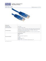
The pin and wire configuration of a patch or crossover cable used to connect or establish a
point-to-point Ethernet LAN between two Ethernet devices is shown here.
FIGURE QS–2: Pin Layout for RJ45 Ethernet Crossover (Patch) Cable
100 metres max length
RJ45 Connectors

QUICK START GUIDE
MULTILINK ML1600/2400 ETHERNET COMMUNICATIONS SWITCH – QUICKSTART GUIDE QS–7
QS.3 Hubs and Switches
Two of the major Ethernet LAN components are "hubs" and "switches." There are many
advantages of a switch over a hub. Hubs just transfer information from one port to all
other ports. Since a hub has no way of handling media contention, collisions can occur
requiring all segments connected to a hub to work in a half duplex mode. Switches on the
other hand have the capability of buffering messages allowing full duplex operation. A
switch will also learn the MAC addresses of devices connected to each of it’s ports and will
then route messages to just the port to which the destination device is connected, thereby
reducing data traffic on the network. Switches that have configuration firmware to
customize the switch and traffic are called “managed switches”. Switches that have fixed
configurations are referred to as “unmanaged switches”.
QS.3.1 Fiber Optic Ethernet:
Fiber optic Ethernet is rapidly becoming the medium of choice in applications where longer
distances and immunity to EMI are of importance, such as power system applications.
However, the higher cost and the difficulty of terminating fiber cables allows twisted pair
to continue to play a roll were appropriate.
The wavelengths of light used in fiber optic communication are 820, 1300 and 1550
nanometers (nm) because it has been found that these wavelengths of light are
attenuated the least as they travel through the fiber optic medium. Compatible ports must
operate at the same wavelength of light and be linked with appropriate fiber. There are
two categories of fiber optic cable: "multi-mode" and "single-mode." Note that until
recently, the cable used with 820nm wavelength light was offered only in multi-mode while
1300nm wavelength light uses both single and multi-mode compatible cable. Cable
compatible with 1550nm wavelength light is offered only in single mode.
Wavelengths of light
Note that both devices must use the same wavelength of light.
Multi-Mode Single-Mode
820nm X X
1300nm X X
1550nm N/A X

QS–8 MULTILINK ML1600/2400 ETHERNET COMMUNICATIONS SWITCH – QUICKSTART GUIDE
QUICK START GUIDE
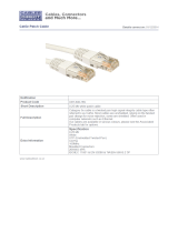
QS.3.2 Single and Multi-mode cable
Fiber Cable Cross Section and Physical Specifications
Multi Mode
• 62.5/125 µm
• 50/125 µm*
Single Mode
• 9/125 µm
* Will become more popular as baud rate goes up
This is a scaled drawing of both a 62.5/ 125 μm multi mode fiber and 9/125 µm single
mode fiber. The outer clad of both is 125 micrometers in diameter. The multi-mode core, at
62.5 micrometers, is a little bit thinner than the average human hair. The core of the 9/125
125µm
62.5µm
CORE
CLAD
8 µm
125 µm
CORE
CLAD

QUICK START GUIDE
MULTILINK ML1600/2400 ETHERNET COMMUNICATIONS SWITCH – QUICKSTART GUIDE QS–9
micrometer fiber is 8 microns in diameter (almost an eighth of that of the Multi-Mode fiber)
surrounded by a second outer clad. This clad can pass a light signal, so for this reason the
fiber is referred to as 9 by 125 micrometer fiber.
FIGURE QS–3: Differences between Multi-Mode and Single-Mode Cable
Single mode fiber - Less attenuation per unit distance
The difference between multi-mode and single mode cable can be best described as
follows:
With multi-mode fiber the index of refraction at the surface between the core and the
cladding is such that there is total internal reflection of the light being transmitted down
the core. Picture this by imagining that the clad is a tube whose interior surface is polished
so smooth, it is like a mirror. Light shinning at one end of the tube will either travel straight
down the tube or will travel down the tube by reflecting of the inner mirrored surface.
Single mode fiber can be described as an elongated lens that is continuously focusing the
light into the centre of the fiber. Using these two analogies it can be imagined that in the
single mode fiber more light travels through far less fiber medium resulting in far less
attenuation per unit distance than it does in multi-mode fiber. As a result, for a given
wavelength of light, single mode fiber typically has less attenuation per unit distance than
multi-mode fiber.

QS–10 MULTILINK ML1600/2400 ETHERNET COMMUNICATIONS SWITCH – QUICKSTART GUIDE
QUICK START GUIDE
QS.4 Optical Power Budget
Inevitably the question that arises is “What is the maximum practical communication
distance when using a fiber optic cable?”. The answer isn’t straightforward, but must be
calculated as follows:
• First the "Optical Power Budget" is determined by subtracting the receiver’s rated
sensitivity from the transmitter’s rated power, both of which are defined in
decibels of light intensity. For example if a particular transmitter is rated at
minus15 db and the receiver’s sensitivity is rated at minus 31 db, the difference of
16 db is the "Optical Power Budget."
Xmt Output Pwr - Rcv Sens = OPB: Optical power budget
Magnum: ( -15.0 dB ) - (- 31.0dB)= -16 dB OPB
The Optical Power Budget can be thought of as the maximum permitted
attenuation of the light signal as it travels from the transmitter to the receiver,
while still permitting reliable communication.
• The next step is to calculate the worst case Optical Power Budget by subtracting
from the Optical Power Budget, 1 dB for LED aging and 1 dB for each pair of
connectors (referred to as "insertion loss").
Worst Case OPB = OPB - 1dB (for LED aging) – 1dB (insertion loss for
each pair of connectors) x number of pairs
The final step is to divide the calculated result by the rated cable loss per kilometer
to determine the maximum distance.
For costly installations it is recommended that you always measure the actual cable loss
before and immediately after the installation to verify that the cable was installed
correctly. To avoid damaging the receiver, ensure that the maximum optical input power of
the receiver isn’t exceeded.
• Worst case distance = {Worst case OPB, in dB} / [Cable Loss, in dB/Km]
where the “typical cable loss” for:
• 62.5/125 and 50/125ìm (M.m) is 2.8 dB/km
• 100/140 (Multi-mode, 850nm) is 3.3 dB/km,
• 9/125 (Single-mode, 1310nm) is 0.5 dB/km (a worst case industry number)
• 9/125 (Single-mode, 1310nm) is 0.4 dB/km ( LXSC25)
• 9/125 (Single-mode 1550nm) is 0.25 dB/km (ZXSC40, SSCX)
• 9/125 (Single-mode 1550nm) is 0.2 dB/km (ZXSC70) and
• 9/125 (Single-mode 1550nm) is 0.22 dB/km (ZXSC120)
These are typical cable losses. There will be deviations depending on the manufacturer.
Always measure the loss before installation.

QUICK START GUIDE
MULTILINK ML1600/2400 ETHERNET COMMUNICATIONS SWITCH – QUICKSTART GUIDE QS–11
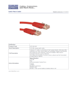
Several styles of connector are used to terminate the attached to the end of the fiber
cable. The ST and SC connectors shown below, are among the more popular. Ensures that
the UR CPU, switch, and cable have compatible connectors.
FIGURE QS–4: Common Fiber Optic Connectors
QS.4.1 Assigning an IP address to the Multilin Switch
The easiest way to configure the switch is through the WEB interface. The switch has been
shipped with a default IP address of 192.168.1.2 and a subnet mask of 255.255.255.0.
Consult your network administrator to determine if the IP address, subnet mask or default
gateway needs to be modified. In our example test network the valid rang of IP addresses
is from 3.94.247.1 to 3.94.247.254.
The easiest way to assign an IP address and subnet mask is through the switches console
serial port. A diagram of the required cable’s pin-out is shown above. Note that both ends
of the cable are terminated in a DB9 pin female connector. Pins 5 of this cable are
DB9 Female to DB9 Female
Cable Pin-out
Pin 2 Pin 2
Pin 3 Pin 3
Pin 5 Pin 5

QS–12 MULTILINK ML1600/2400 ETHERNET COMMUNICATIONS SWITCH – QUICKSTART GUIDE
QUICK START GUIDE
connected together while pin 2 at one end is connected to pin 3 at the other end. Once you
have obtained a cable with this pin configuration, connect one end to the computer’s
serial port and the other to the Multilink switch port.
The Hyperterminal utility application is a convenient standard firmware tool that will be
used to configure the switch. This program is found on most windows based operating
systems under programs > accessories > communications > Hyperterminal.
Z Once the HyperTerminal application is launched you will need to
cancel HyperTerminal’s dial sequence by left mouse clicking on the
Cancel pushbutton. This will allow you to access Hyperterminal’s
configuration menus.

QUICK START GUIDE
MULTILINK ML1600/2400 ETHERNET COMMUNICATIONS SWITCH – QUICKSTART GUIDE QS–13
Z Select an icon and name to use for saving the new Hyperterminal
configuration.

QS–14 MULTILINK ML1600/2400 ETHERNET COMMUNICATIONS SWITCH – QUICKSTART GUIDE
QUICK START GUIDE
Z Select the computer’s serial port that is connected to the Multilink
switch.
Z Select OK.
Z In the next window set the baud rate to 38400, data bits to 8, no
parity, one stop bit and set the flow control to none.
Z Left mouse click on the OK icon to attempt communication to the
Multilink switch.

QUICK START GUIDE
MULTILINK ML1600/2400 ETHERNET COMMUNICATIONS SWITCH – QUICKSTART GUIDE QS–15
Z Press the Enter key until the message Hit <Enter> to log into
ML1600/2400 system is displayed.
Z Press the Enter key one more time to get the login prompt.
Z Enter the login name manager and the default password
manager.
Once you are successfully logged in, the prompt will change to the
model number of the switch you are connected to, followed by the
pound (#) sign, indicating a successful login.

QS–16 MULTILINK ML1600/2400 ETHERNET COMMUNICATIONS SWITCH – QUICKSTART GUIDE
QUICK START GUIDE
In this example the switch that the computer is connected to is a Multilink ML1600.
The instruction manual for the MultiLink provides a list of all instructions. A valid IP address
and subnet mask can be programmed into the switch using the IP config command as
follows:
Z Type ipconfig ip=, then enter the IP address (in our example we will
use a unique address between 3.94.244.1 and 3.94.244.254),
followed by a space.
Z Type mask=
Z Enter the mask (in our example system we would use
255.255.252.0).
Z If a default gateway is also required enter a space and type dgw=
Z Enter the ip address of the gateway.
/