
T874G Thermostats
and Q674F,J Subbases
for Heat Pump Systems
J.H. • Rev. 7-94 • • ©Honeywell Inc. 1994 • Form Number 69-0435—10
TRADELINE
®
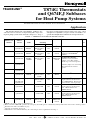
TABLE 1—THERMOSTAT/SUBBASE SPECIFICATIONS.
Application
The T874G Thermostats and Q674F,J Subbases pro-
vide 24 to 30 Vac control of 2-stage heating and 1-stage cool-
ing heat pump systems with automatic changeover. Stage 1
heat and cool anticipation is fixed voltage type; stage 2 heat
anticipation is adjustable (except as noted). See Table 1 for
specific T874G/Q674F,J combinations and specifications.
Installation Instructions for the Trained Service Technician.
Thermostat/
Subbase
Thermostat/
Subbase
Model LED
Switching
See
Package Numbers Indication
System Fan Changeover Comments
Fig.
Y594G1252 T874G1246/
Q674F1212
AUX.HT.,
EM.HT.
a
EM.HT.-OFF-
HEAT-AUTO-
COOL
AUTO-
ON
AUTO,
COOL
TRADELINE
®
5
— T874G1246/
Q674F1410
AUX.HT.,
EM.HT.
a
EM.HT.
b
-OFF-
HEAT-AUTO-
COOL
AUTO-
ON
AUTO,
COOL
Separate W1 and Y1
terminals; TRADELINE
®
subbase.
6
Y594G1419 T874G1642/
Q674F1444
AUX.HT.,
EM.HT.,
CHECK
OFF-EM.HT.-
HEAT-AUTO-
COOL
AUTO-
ON
AUTO,
HEAT OR
COOL
SUPER TRADELINE
®
;
includes factory-installed
jumper across W1 and Y1;
fixed stage 2 heat anticipation.
7
Y594G1476
c
T874G1741/
Q674F1477
Isolated CHECK LED
includes jumper for connecting
X2 terminal to X or R for
power.
Y594G1534
d
T874G1824/
Q674F1477
Y594G1526 T874G1626/
Q674F1436
AUX.HT.,
EM.HT.
OFF-EM.HT.-
HEAT-AUTO-
COOL
AUTO-
ON
AUTO,
HEAT
TRADELINE
®
8
— T874D1165
or
T874E1016/
Q674F1543
(RED)
e
OFF-EM.HT.-
HEAT-AUTO-
COOL
AUTO-
ON
AUTO TRADELINE
®
subbase; exact
replacement for York model
no. 2TB04700524. Thermostat
not included; order separately.
9
Y594G1567 T874G1865/
Q674J1209
EM.HT. EM.HT.-
AUTO-OFF
AUTO-
ON
AUTO,
COOL
TRADELINE
®
; exact
replacement for York model
nos. 2TH11702424 and
6TH11702424.
10
Y594G1575
c
T874G1873/
Q674J1225
EM.HT. EM.HT.-
AUTO-OFF
AUTO-
ON
AUTO,
COOL
TRADELINE
®
; exact
replacement for York model
nos. 2TH11702424 and
6TH11702424.
10
Y594G1633 T874G1972/
Q674F1584
AUX.HT.,
EM.HT.
OFF-EM.HT.-
HEAT-AUTO-
COOL
AUTO-
ON
AUTO,
HEAT OR
COOL
TRADELINE
®
11
a
EM.HT. also shows compressor malfunction.
b
When switch is in EM. HT. position, the emergency heat will operate continuously until system switch is moved to another position.
c
Thermostat is white and subbase is gray.
d
Sold only in Australia; degrees C.
e
LED indicator is not labeled but may be connected per user's requirements. See Fig. 9.
M3375

69-0435—10 2
IMPORTANT: Thermostats are calibrated at the factory by
using subbases mounted at true level. Inaccurate sub-
base leveling will cause thermostat control deviation.
LOCATION
Install the thermostat about 5 ft [1.5 m] above the
floor in an area with good air circulation at average
temperature.
Do not install the thermostat where it can be affected
by:
• drafts, or dead spots behind doors and in cor-
ners.
• hot or cold air from ducts.
• radiant heat from sun or appliances.
• concealed pipes and chimneys.
• unheated (uncooled) areas such as an outside
wall behind the thermostat.
MOUNTING THE SUBBASE
The thermostat subbase can be mounted on a vertical
outlet box, horizontal outlet box or directly on the wall.
1. If you must mount the subbase on a vertical outlet
box, order 193121A (beige) or 202689A (gray) Adapter
Assembly. See Fig. 1. The assembly includes an adapter ring,
two screws and a cover plate to cover marks on the wall. Install
the ring and cover plate on the vertical outlet box.
For a wall installation, hold subbase in position and
mark holes for anchors. See Fig. 2. Obtain wall anchors
locally. Set subbase aside. Drill four 3/16 in. [5 mm] holes
and gently tap anchors into the holes until flush with the wall.
2. Run wires to the thermostat location. See wiring
diagrams, Figs. 5-11.
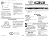
Fig. 1—Installation of Q674 Subbase on outlet
box.
M925
VERTICAL
OUTLET
BOX
ADAPTER
RING
SUBBASE
COVER
PLATE
MOUNTING
SCREWS (2)
MOUNTING
SCREWS (2)
1
SUBBASE
MOUNTING
SCREWS (2)
HORIZONTAL
OUTLET
BOX
1
2
2
1 NOT INCLUDED WITH UNIT.
2 ACCESSORY PARTS AVAILABLE (193121A).
Recycling Notice
This control contains mercury in a sealed tube. Do not
place control in the trash at the end of its useful life.
If this control is replacing a control that contains mercury
in a sealed tube, do not place your old control in the trash.
Contact your local waste management authority for
instructions regarding recycling and the proper disposal
of this control, or of an old control containing mercury in
a sealed tube.
M3375
Installation
WHEN INSTALLING THIS PRODUCT…
1. Read these instructions carefully. Failure to
follow them could cause a hazardous condition.
2. Check the ratings given in the instructions and on
the product to make sure the product is suitable for your
application.
3. Installer must be a trained, experienced service
technician.
4. After installation is complete, check out product
operation as provided in these instructions.
CAUTION
1. Disconnect power supply to prevent electri-
cal shock or equipment damage.
2. To prevent interference with the thermostat
linkage, keep wire length to a minimum and
run wires as close as possible to the subbase.
3. Do not overtighten thermostat captive mount-
ing screws because damage to subbase threads
can result.
4. Do not short across coil terminals on relay. This
may burn out the thermostat heat anticipator.
5. Never install more than one wire per termi-
nal unless factory-supplied jumper with spade
terminal is used.
!
Operation
On a 2-stage heating thermostat, the two stages of heat
make sequentially as the temperature drops. Make refers to
the mercury switch initiating a call for heat or cool.
There are about 2° F [1° C] between stages so the
sec-ond stage makes only when the first stage cannot
handle the load. This 2° F [1° C] is referred to as the
interstage differential.
The LED indicators are light emitting diodes on the
subbase that light up when something specific happens
within the system. When an LED lights up, refer to the
following list for the meaning:
EM.HT.: Emergency heat is operating, which means
the system switch is at EM. HT.
AUX.HT.: Auxiliary heat is operating, which means
the weather is so cold that the heat pump can not
handle the load alone.
CHECK: System needs to be checked. See Heating/
Cooling System Instructions for specific meaning.
LEDs are not field replaceable or addable.

3 69-0435—10
Fig. 2—Installation of Q674 Subbase on wall.
WIRES THROUGH
WALL OPENING
WALL
WALL
ANCHORS
(2)
SUBBASE
MOUNTING
HOLES
MOUNTING
SCREWS (2)
M926
Fig. 3—Subbase components and leveling
procedure.
SPIRIT LEVEL
MOUNTING HOLES (2)
M927
TOP MOUNTING HOLES (2)
WIRING
TERMINAL
THERMOSTAT
CABLE OPENING
TO SPRING FINGER CONTACTS
ON THE THERMOSTAT
(UP TO 12)
POST (2) FOR
MOUNTING
THERMOSTAT
IMPORTANT: Use 18 gauge, color-coded thermostat
cable for proper wiring.
3. Pull wires through the cover plate (if used) and
sub-base cable opening. See Fig. 3. Take care that wires
do not fall back into the wall opening.
4. Secure the cover plate (if used) and subbase with the
screws provided. Do not fully tighten the subbase screws.
5. Level the subbase using a spirit level, as shown in
Fig. 3, and firmly tighten subbase mounting screws.
The subbase mounting holes provide for minor out-of-
level adjustments.
IMPORTANT: An incorrectly leveled subbase will cause
the temperature control to deviate from set point.
WIRING THE SUBBASE
All wiring must comply with local electrical codes and
ordinances. Follow equipment manufacturer wiring instruc-
tions when available. To wire subbase, proceed as follows:
Fig. 4—Wiring Connections.
FOR STRAIGHT
INSERTION–
STRIP 5/16 in. [8 mm]
FOR WRAPAROUND–
STRIP 7/16 in. [11 mm]
SUBBASE TERMINAL SCREW
M928
BARRIER
1. Connect the system wires to the subbase as shown
in Figs. 5-11. A letter code located near each terminal is
for identification. The terminal barrier permits straight or
conventional wraparound wiring connection. See Fig. 4.
2. Firmly tighten each terminal screw.
3. Fit wires as close as possible to the subbase. Push
excess wire back into the hole.
4. Plug hole with nonflammable insulation to pre-
vent drafts from affecting the thermostat.

69-0435—10 4
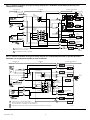
Fig. 5—Internal schematic and typical wiring diagram for Y594G1252 (T874G1246/Q674F1212); auto
changeover in cooling.
H2
FALL
L1
(HOT)
L2
1
R
W3
W2
X
L
G
O
E
Y
RTD1 OTD1
EHR1
ODT2
EHR2
RTD2
RTD3
RTD1
SYSTEM
MONITOR
FAN
RELAY
RD
COOL
CHANGEOVER VALVE
EM. HEAT
RELAY
LACO
COMPRESSOR
CONTACTOR
CHP
2
3
4
5
6
8
9
10
H1
FALL
H1 ANTICIPATOR
H2
ANTICIPATOR
CHANGEOVER
RISE
C1
RISE
C1
ANTICIPATOR
OFF
COOL
AUTO
HEAT
EM. HT.
SYSTEM
SWITCH
AUTO
ON
FAN
SWITCH
AUX. HEAT
LED (GRN)
EM. HEAT
LED (RED)
POWER SUPPLY. PROVIDE DISCONNECT MEANS AND OVERLOAD
PROTECTION AS REQUIRED.
W3 TERMINAL ON SELECT MODELS.
1
2
2
M1589
THERMOSTAT
SUBBASE
SYSTEM COMPONENTS
Fig. 6—Internal schematic and typical wiring diagram for T874G1246/Q674F1410. Separate W1 and Y1
terminals can be jumpered together to form Y terminal.
H1
FALL
RISE
CO
L1
(HOT)
L2
1
C1
RISE
1
2
3
3
2
POWER SUPPLY. PROVIDE DISCONNECT
MEANS AND OVERLOAD PROTECTION AS REQUIRED.
ON SOME MODELS, Y TERMINAL MAY BE LABELED Y1.
EMERGENCY HEAT RUNS CONTINUOUSLY WHEN SWITCH IN IN EM. HT. POSITION.
C1 ANTICIPATOR
H1 ANTICIPATOR
FAN SWITCH
AUTO
ON
SYSTEM
SWITCH
AUTO
HEAT
OFF
COOL
2
4
8
9
10
W2
X
L
B
R
G
Y
AUX. HEAT RELAY
FAN RELAY
EM. HT.
RELAY
B RELAY
M5987A
THERMOSTAT SUBBASE SYSTEM COMPONENTS
COMPRESSOR
CONTACTOR
EM. HT.
EM. HT.
LED (RED)
AUX. HEAT
LED (GREEN)
H2
FALL
H2
ANTICIPATOR
3
5
W3
W1
W3 RELAY
W1 RELAY
COOL
CHANGEOVER
VALVE
COMPRESSOR
FAULT
E
O
6

5 69-0435—10
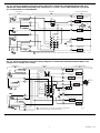
Fig. 7—Internal schematic and typical wiring diagram for Y594G1419 (T874G1642/Q674F1444),
Y594G1476 (T874G1741/Q674F1477) and Y594G1534 (T874G1824/Q674F1477 sold only in Australia); auto
changeover in heating and cooling; fixed anticipation. CHECK LED has isolated terminals. Factory-
installed W1-Y1 jumper is equivalent to Y terminal.
CHANGEOVER
(HEAT)
FALL
H2
FALL
RISE
H1
FALL
L1
(HOT)
L2
1
2
1
2
RISE
C1
POWER SUPPLY. PROVIDE DISCONNECT MEANS AND OVERLOAD PROTECTION AS REQUIRED.
W1 - Y1 JUMPER IS Y TERMINAL; REMOVE JUMPER WHEN W1 RELAY IS USED.
THERMOSTAT
SUBBASE
SYSTEM COMPONENTS
M1230A
1
2
3
4
5
6
8
9
10
11
Y1
W1
B
O
X
X1
E
W2
R
G
W3
X2
W3 RELAY
FAN RELAY
AUX. HEAT
RELAY
EM. HT.
RELAY
COMPRESSOR
FAULT
CHECK
LED (RED)
AUX.
HT. LED
(GREEN)
EM. HT.
LED (RED)
SYSTEM
SWITCH
OFF
EM. HT.
HEAT
AUTO
COOL
COOL CHANGEOVER
RELAY
HEAT CHANGEOVER
RELAY
W1 RELAY
COMPRESSOR
CONTACTOR
C1
ANTICIPATOR
CHANGEOVER
(COOL)
H2 ANTICIPATOR
H1
ANTICIPATOR
FAN
SWITCH
AUTO
ON

69-0435—10 6
Fig. 8—Internal schematic and typical wiring diagram for Y594G1526 (T874G1626/Q674F1436); auto
changeover in heating.
M1592A
(HOT) L1
L2
1
LACO
CHP
Y
B
E
G
L
X
W2
R
ODT 1
RTD 1 EHR 1
RTD 2
ODT 2
EHR 2 RTD 3
RD
COMPRESSOR
FAILURE
FAN RELAY
COMPRESSOR
CONTACTOR
HEAT
CHANGEOVER
VALVE
EM. HT.
RELAY
RTD 1
AUX. HEAT
LED (GREEN)
EM. HT.
LED (RED)
FAN SWITCH
ON
AUTO
SYSTEM
SWITCH
EM. HT.
HEAT
AUTO
OFF
COOL
H2
FALL
H1
FALL
2
3
4
5
H1 ANTICIPATOR
H2
ANTICIPATOR
C1
RISE
FALL
7
8
9
10
C1
ANTICIPATOR
1
POWER SUPPLY. PROVIDE DISCONNECT MEANS AND OVERLOAD PROTECTION AS REQUIRED.
THERMOSTAT
SUBBASE
SYSTEM COMPONENTS
EHT1
CHANGEOVER
Fig. 9—Internal schematic and typical wiring diagram for T874D1165, T874E1016/Q674F1543. Exact
replacement for York model no. 2TB04700524.
H1
FALL
W1
G
W2
B
HEAT RELAY 1
HEAT
OFF
COOL
SYSTEM
SWITCH
H1 ANTICIPATOR
C1 ANTICIPATOR
AUTO
ON
FAN
SWITCH
1
2
POWER SUPPLY. PROVIDE DISCONNECT MEANS AND OVERLOAD PROTECTION AS REQUIRED.
LED IS NOT LABELED. JUMPER W2 TO X FOR AUXILIARY HEAT INDICATION. JUMPER E TO X FOR
EMERGENCY HEAT INDICATION. CONNECT SYSTEM MONITOR TO X TO IDENTIFY WHEN SYSTEM
NEEDS TO BE CHECKED.
M2982A
THERMOSTAT
SUBBASE
SYSTEM COMPONENTS
R
EM. HEAT RELAY
COMPRESSOR
CONTACTOR 2
COMPRESSOR
CONTACTOR 1
1
4
6
8
9
10
11
H2
FALL
C2 ANTICIPATOR
RISE
RISE
C1
C2
Y1
Y2
HEAT RELAY 2
L1
(HOT)
L2
1
2
LED
(RED)
H2
ANTICIPATOR
AUTO
EM. HT.
X
E
FAN RELAY

7 69-0435—10
Fig. 10—Internal schematic and typical wiring diagram for Y594G1567 (T874G1865/Q674J1209) and
Y594G1575 (T874G1873/Q674J1225); auto changeover in cooling. Exact replacement for York model
nos. 2TH11702424 and 6TH11702424.
EM. HT.
AUX. HEAT RELAY
POWER SUPPLY. PROVIDE DISCONNECT MEANS AND OVERLOAD PROTECTION AS REQUIRED.
1
RISE
CO
RISE
C1
6
8
9
10
X
B
Y
COMPRESSOR
CONTACTOR
FALL
H2
5
W
4
SYSTEM COMPONENTSSUBBASETHERMOSTAT
H1 ANTICIPATOR
2
L1
(HOT)
L2
1
FALL
H1
3
O
G
R
FAN RELAY
COOL CHANGEOVER VALVE
H2 ANTICIPATOR
C1 ANTICIPATOR
FAN
SWITCH
AUTO
ON
SYSTEM
SWITCH
AUTO
OFF
EM. HEAT
LED (RED)
M5723
EM. HEAT RELAY
Fig. 11—Internal schematic and typical wiring diagram for Y594G1633 (T874G1972/Q674F1584); auto
changeover in heating and cooling.
H1
FALL
RISE
CO
L1
(HOT)
L2
1
C1
RISE
1
POWER SUPPLY. PROVIDE DISCONNECT MEANS AND
OVERLOAD PROTECTION AS REQUIRED.
C1 ANTICIPATOR
H1 ANTICIPATOR
FAN SWITCH
AUTO
ON
SYSTEM
SWITCH
AUTO
HEAT
OFF
COOL
1
2
4
6
8
9
10
O
W2
X
E
L
B
R
G
Y
AUX. HEAT RELAY
FAN RELAY
EM. HT. RELAY
B RELAY
M5986
THERMOSTAT SUBBASE SYSTEM COMPONENTS
11
12
COMPRESSOR
CONTACTOR
EM. HT.
EM. HT.
LED (RED)
AUX. HEAT
LED (GREEN)
COOL CHANGEOVER
VALVE
H2
FALL
H2
ANTICIPATOR

69-0435—10 8
MOUNTING THE THERMOSTAT
1. Remove the thermostat cover by pulling the bot-
tom edge of the cover away from the base until it snaps
free of the retaining posts.
NOTE: The cover is hinged at the top and must be
removed by pulling out at the bottom.
2. Carefully remove and discard the foam packing in-
sert that protects the mercury switches during shipment.
3. If thermostat is being used with a Q674 Subbase
that has LED indication, and the thermostat set point
scale does not have preprinted designations (EM.HT.,
CHECK, etc.), install the desired preprinted insert
packed with the subbase. Push both thermostat set
point levers to the far ends of the thermostat. Use index
finger to gently pull out the set point scale a fraction of
an inch. Insert the desired preprinted insert into the
recessed area behind the set point scale. Make sure
insert is completely seated in recessed area and reposi-
tion set point levers to the desired positions.
4. Turn over the thermostat base and note the spring
fingers that engage the subbase contacts. Make sure the
spring fingers are not bent flat, preventing proper elec-
trical contact with the subbase.
5. Set any adjustable heat anticipator indicators to
the respective current setting of each stage. See Setting
the Heat Anticipator section.
6. Note the tabs along the top inside edge of the
thermostat base. The tabs fit into the subbase notches.
Mount the thermostat base on the subbase and tighten
the captive mounting screws. See Fig. 12.
7. Place the upper edge of the thermostat cover on
the thermostat base and swing the cover downward until
it engages with the retaining posts on the base.
Fig. 12—Mounting thermostat on subbase.
THERMOSTAT
MOUNTING POST (2)
M936
50 60 70 80
50 60 70 80
HEAT
COOL
THERMOSTAT
MOUNTING SLOTS (2)
SUBBASE
THERMOSTAT
CAPTIVE MOUNTING
SCREWS (2)
Setting
SETTING THE HEAT ANTICIPATOR
On models with adjustable anticipation, set each ad-
justable anticipator to match the primary control current
draw. If the primary control nameplate has no rating or if
further adjustment is necessary, use the following proce-
dure to determine the current draw for each stage.
!
The current draw must be measured with the thermo-
stat removed and the power on.
Do not short across primary control terminals. This
may burn out the heat anticipator.
1. Connect an ac ammeter of appropriate range be-
tween the heating terminals of the subbase as follows:
• Stage 1: between W1 and RH or R.
• Stage 2: between W2 and RH or R.
2. Move the system switch to HEAT or AUTO, and
set the temperature to call for heat.
3. After one minute, read the ammeter and record
the reading.
4. After mounting the thermostat, set the adjustable
heat anticipator to match the readings measured in step 3.
TEMPERATURE SETTING
Move the heating and the cooling levers to the desired
positions. The minimum differential between heating and
cooling set points is 4° or 6° F [2° or 3° C], depending
on model; the setting levers are designed so they
cannot be set closer together than 4° or 6° F [2° or 3°
C], depending on the model.
SUBBASE SETTING
CAUTION
The Q647F1410 will run the EM. HT. relay
constantly when the system is in the EM. HT.
position. A cycling stat or limit must be pro-
vided external to the T874 to control the EM.
HT. relay.
System switching positions control thermostat op-
eration as follows:
OFF: Both the heating and cooling systems are off.
HEAT: Heating system is controlled by the thermo-
stat. Cooling system is off.
COOL: The cooling system is controlled by the
thermostat. Heating system is off.
EM.HT.: Emergency heat relay is energized. The cool-
ing system is off. When the heat pump is inoperable,
switch to EM. HT. setting. The Q674F1410 Subbase
will run EM. HT. relay continuously until the switch
position is changed. All other subbases will cycle
the EM. HT. relay according to room temperature
via the T874 mercury switch.
AUTO: Thermostat automatically changes between heat
and cool modes, depending on the indoor temperature.
Fan switching positions control fan operation as follows:
ON: Fan operates continuously.
AUTO: Fan operates with heating or cooling equip-
ment as controlled by the thermostat.
To switch positions, use thumb or index finger to
slide the lever to the desired position. Switch lever must
stop in detent over the desired function indicator mark
for proper circuit operation.

9 69-0435—10
Checkout
HEATING
Move the system switch on the Q674 Subbase to
HEAT. Move the heating set point lever on the T874
Thermostat about 10° F [6° C] above room tempera-
ture. Both stages of heating and fan should start. Move
the set point lever about 10° F [6° C] below room
temperature. Heating and fan should shut off.
NOTE: To prevent compressor short cycling, a minimum
off-timer may be included to provide a five-minute time
delay before turning on the compressor after the thermo-
stat last turned off the compressor, or after the system
first received power. This delay protects the compressor.
COOLING
CAUTION
Do not operate cooling if the outdoor tempera-
ture is below 50° F [10° C]. Refer to manufac-
turer recommendations.
Move the system switch on the Q674 Subbase to
COOL. Move the cooling set point lever on the T874
Thermostat about 10° F [6° C] below room tempera-
ture. Cooling and fan should start (see CAUTION).
Move the cooling set point lever about 10° F [6° C]
above room temperature. Cooling and fan should stop.
EMERGENCY HEAT
Change the system switch to EM. HT. The EM. HT.
LED will come on. The Q674F1410 Subbase starts the
electric strip heater(s) when put in the EM. HT. position
(see CAUTION in Subbase Setting section). All other
subbases will be tested by moving the set point lever
about 10° F [6° C] above room temperature. The electric
strip heater(s) will come on. Reset the set point lever
about 10° F [6° C] below room temperature. The electric
strip heater will de-energize. The EM. HT. LED remains
on until the system switch is moved to another position.
FAN
Move the subbase system switch to OFF, and the fan
switch to ON. The fan should run continuously. When
the fan switch is in the AUTO position, the fan operates
with the heating or cooling equipment.
Calibration
THERMOSTAT
T874 Thermostats are accurately calibrated at the
factory. They do not have provision for field calibration.
THERMOMETER
1. Remove thermostat cover by pulling the bottom
edge of the cover away from the base until it snaps free
from the retaining posts.
2. Set the cover on a table near an accurate thermometer.
3. After allowing 10 or 15 minutes for stabilization,
compare the readings. If they are the same, replace the
cover and put the system into operation. If they are
different, recalibrate the thermostat thermometer, step 4.
4. Insert a small screwdriver in the thermometer shaft
(Fig. 13) and turn it until the thermometers read the
same. When the thermometer is calibrated, replace the
cover and place the system into operation.
NOTE: Hand heat will offset the thermometer reading.
After making each adjustment, wait 10 or 15 minutes
for the thermometer to stabilize before comparing.
Fig. 13—Thermometer calibration.
M5070
!

69-0435—10 10

11 69-0435—10

Home and Building Control Home and Building Control
Honeywell Honeywell Limited—Honeywell Limitée
1985 Douglas Drive North 35 Dynamic Drive
Golden Valley, Minnesota 55422 Scarborough, Ontario
M1V 4Z9
69-0435–10 Printed in U.S.A.
-
 1
1
-
 2
2
-
 3
3
-
 4
4
-
 5
5
-
 6
6
-
 7
7
-
 8
8
-
 9
9
-
 10
10
-
 11
11
-
 12
12


Ask a question and I''ll find the answer in the document
Finding information in a document is now easier with AI
Related papers
-
Honeywell CT50A User manual
-
Honeywell T822K1018 Operating instructions
-
Honeywell Super Tradeline Y594G User manual
-
-
-
-
-
-
-
Other documents
-
King Electric HET-2R User guide
-
Bryant Q674 User manual
-
 Hunter Fan 43302 Owner's manual
-
White Rodgers 1F56W-911 User manual
-
 Hunter Fan 43007 User manual
-
-
-
Lux Products LHP-750 User manual
-
-
Robertshaw 200-401 Owner's manual

