LG-Nortel ELO ES24 User manual
- Category
- Network switches
- Type
- User manual
This manual is also suitable for

LG-Nortel ELO ES24
(LNES24)
Fast Ethernet Switch
User Guide

Copyright
Information furnished by LG-Nortel Co.Ltd.(LG-Nortel) is believed to be accurate and
reliable. However, no responsibility is assumed by for its use, nor for any infringements
of patents or other rights of third parties which may result from its use. No license is
granted by implication or otherwise under any patent or patent rights of LG-NORTEL.
LG-NORTEL reserves the right to change specifications at any time without notice.
Copyright © 2008 by
LG-NORTEL Co.Ltd.
GS Tower, 679 Yoksam-dong,
Kangnam-gu, Seoul, 135-985,Korea
All rights reserved. Printed in Taiwan
Trademarks:
LG-NORTEL is a registered trademark; Other product and company names are trademarks or
registered trademarks of their respective holders.

ii
L
IMITED
W
ARRANTY
Limited Warranty Statement:
LG-Nortel warrants the Products, excluding consumable items to be free from defective design
attributable to LG-Nortel, defective material or faulty workmanship and will conform to the
Specifications for twelve (12) months from the date of Customer acceptance of the Product.

iii
WARRANTIES EXCLUSIVE: IF AN LG-NORTEL PRODUCT DOES NOT OPERATE
AS WARRANTED ABOVE, CUSTOMER.S SOLE REMEDY SHALL BE REPAIR OR
REPLACEMENT OF THE PRODUCT IN QUESTION, AT LG-NORTEL’S OPTION. THE
FOREGOING WARRANTIES AND REMEDIES ARE EXCLUSIVE AND ARE IN
LIEU OF ALL OTHER WARRANTIES OR CONDITIONS, EXPRESS OR IMPLIED,
EITHER IN FACT OR BY OPERATION OF LAW, STATUTORY OR OTHERWISE,
INCLUDING WARRANTIES OR CONDITIONS OF MERCHANTABILITY AND
FITNESS FOR A PARTICULAR PURPOSE. LG-NORTEL NEITHER ASSUMES NOR
AUTHORIZES ANY OTHER PERSON TO ASSUME FOR IT ANY OTHER
LIABILITY IN CONNECTION WITH THE SALE, INSTALLATION,
MAINTENANCE OR USE OF ITS PRODUCTS. LG-NORTEL SHALL NOT BE LIABLE
UNDER THIS WARRANTY IF ITS TESTING AND EXAMINATION DISCLOSE THE
ALLEGED DEFECT IN THE PRODUCT DOES NOT EXIST OR WAS CAUSED BY
CUSTOMER.S OR ANY THIRD PERSON.S MISUSE, NEGLECT, IMPROPER
INSTALLATION OR TESTING, UNAUTHORIZED ATTEMPTS TO REPAIR, OR
ANY OTHER CAUSE BEYOND THE RANGE OF THE INTENDED USE, OR BY
ACCIDENT, FIRE, LIGHTNING, OR OTHER HAZARD.
LIMITATION OF LIABILITY: IN NO EVENT, WHETHER BASED IN CONTRACT
OR TORT (INCLUDING NEGLIGENCE), SHALL LG-NORTEL BE LIABLE FOR
INCIDENTAL, CONSEQUENTIAL, INDIRECT, SPECIAL, OR PUNITIVE
DAMAGES OF ANY KIND, OR FOR LOSS OF REVENUE, LOSS OF BUSINESS, OR
OTHER FINANCIAL LOSS ARISING OUT OF OR IN CONNECTION WITH THE
SALE, INSTALLATION, MAINTENANCE, USE, PERFORMANCE, FAILURE, OR
INTERRUPTION OF ITS PRODUCTS, EVEN IF LG-NORTEL OR ITS AUTHORIZED
RESELLER HAS BEEN ADVISED OF THE POSSIBILITY OF SUCH DAMAGES.
SOME STATES DO NOT ALLOW THE EXCLUSION OF IMPLIED WARRANTIES
OR THE LIMITATION OF INCIDENTAL OR CONSEQUENTIAL DAMAGES FOR
CONSUMER PRODUCTS, SO THE ABOVE LIMITATIONS AND EXCLUSIONS
MAY NOT APPLY TO YOU. THIS WARRANTY GIVES YOU SPECIFIC LEGAL
RIGHTS, WHICH MAY VARY FROM STATE TO STATE. NOTHING IN THIS
WARRANTY SHALL BE TAKEN TO AFFECT YOUR STATUTORY RIGHTS.
* LG-NORTEL will provide warranty service for one year following discontinuance from the
active LG-NORTEL price list. Under the limited lifetime warranty, internal and external power
supplies, fans, and cables are covered by a standard one-year warranty from date of purchase.
LG-NORTEL Co.Ltd.
GS Tower, 679 Yoksam-dong,
Kangnam-gu, Seoul, 135-985,Korea

iv
C
OMPLIANCES
FCC - Class A
This equipment has been tested and found to comply with the limits for a Class A digital
device, pursuant to Part 15 of the FCC Rules. These limits are designed to provide reasonable
protection against harmful interference in a residential installation. This equipment generates,
uses and can radiate radio frequency energy and, if not installed and used in accordance with
instructions, may cause harmful interference to radio communications. However, there is no
guarantee that the interference will not occur in a particular installation. If this equipment
does cause harmful interference to radio or television reception, which can be determined by
turning the equipment off and on, the user is encouraged to try to correct the interference by
one or more of the following measures:
• Reorient the receiving antenna
• Increase the separation between the equipment and receiver
• Connect the equipment into an outlet on a circuit different from that to which the receiver is
connected
• Consult the dealer or an experienced radio/TV technician for help
Industry Canada - Class A
This digital apparatus does not exceed the Class A limits for radio noise emissions from
digital apparatus as set out in the interference-causing equipment standard entitled .Digital
Apparatus,. ICES-003 of the Department of Communications.
Cet appareil numérique respecte les limites de bruits radioélectriques applicables aux appareils
numériques de Classe A prescrites dans la norme sur le matériel brouilleur: .Appareils
Numériques,. NMB-003 édictée par le ministère des Communications.
EC Conformance Declaration - Class A
LG-NORTEL contact for these products is:
LG-NORTEL Co.Ltd.
GS Tower, 679 Yoksam-dong,
Kangnam-gu, Seoul, 135-985,Korea
This information technology equipment complies with the requirements of the Council
Directive 89/336/EEC on the Approximation of the laws of the Member States relating to
Electromagnetic Compatibility and 73/23/EEC for electrical equipment used within certain

v
voltage limits and the Amendment Directive 93/68/EEC. For the evaluation of the
compliance with these Directives, the following standards were applied:
RFI Emission:
• Limit class A according to EN 55022:1998, IEC 60601-1-2 (EMC, medical)
• Limit class A for harmonic current emission according to EN 61000-3-2/1995
• Limitation of voltage fluctuation and flicker in low-voltage supply system according to
EN 61000-3-3/1995
Immunity:
• Product family standard according to EN 55024:1998
• Electrostatic Discharge according to EN 61000-4-2:1995
(Contact Discharge: ±4 kV, Air Discharge: ±8 kV)
• Radio-frequency electromagnetic field according to EN 61000-4-3:1996
(80 - 1000 MHz with 1 kHz AM 80% Modulation: 3 V/m)
• Electrical fast transient/burst according to EN 61000-4-4:1995 (AC/DC
power supply: ±1 kV, Data/Signal lines: ±0.5 kV)
• Surge immunity test according to EN 61000-4-5:1995
(AC/DC Line to Line: ±1 kV, AC/DC Line to Earth: ±2 kV)
• Immunity to conducted disturbances, Induced by radio-frequency fields:
EN 61000-4-6:1996 (0.15 - 80 MHz with
1 kHz AM 80% Modulation: 3 V/m)
• Power frequency magnetic field immunity test according to
EN 61000-4-8:1993 (1 A/m at frequency 50 Hz)
• Voltage dips, short interruptions and voltage variations immunity test
according to EN 61000-4-11:1994 (>95% Reduction @10 ms, 30%
Reduction @500 ms, >95% Reduction @5000 ms)
LVD:
•
EN 60950-1:2001

vi
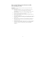
Please read the following safety information carefully
before installing the Switch:
WARNING: Installation and removal of the unit must be carried out by
qualified personnel only.
• This guide is intended for use by network administrators who are
responsible for setting up and installing network equipment;
consequently it assumes a basic working knowledge of LANs (Local
Area Networks).
• The unit must be connected to an earthed (grounded) outlet to
comply with international safety standards.
• Do not connect the unit to an A.C. outlet (power supply) without an
earth (ground) connection.
• The appliance coupler (the connector to the unit and not the wall plug)
must have a configuration for mating with an EN 60320/IEC 320
appliance inlet.
• The socket outlet must be near to the unit and easily accessible. You
can only remove power from the unit by disconnecting the power
cord from the outlet.
• This unit operates under SELV (Safety Extra Low Voltage) conditions
according to IEC 60950. The conditions are only maintained if the
equipment to which it is connected also operates under SELV
conditions.

vii
France and Peru only
This unit cannot be powered from IT
.
supplies. If your supplies are of IT type, this unit must
be powered by 230 V (2P+T) via an isolation transformer ratio 1:1, with the secondary connection
point labelled Neutral, connected directly to earth (ground).
†Impédance à la terre
Power Cord Set
The cord set must be UL-approved and CSA certified.
The minimum specifications for the flexible cord are: - No. 18
AWG - not longer than 2 meters, or 16 AWG. - Type SV or SJ -
3-conductor
The cord set must have a rated current capacity of at least 10A.
U.S.A. and Canada
The attachment plug must be an earth-grounding type with
NEMA 5-15P (15 A, 125 V) or NEMA 6-15P (15 A, 250 V)
configuration.
Denmark
The supply plug must comply with Section 107-2-D1, Standard
DK2-1a or DK2-5a.
Switzerland The supply plug must comply with SEV/ASE 1011.
The supply plug must comply with BS1363 (3-pin 13 A) and be
fit-ted with a 5 A fuse which complies with BS1362.
U.K.
The mains cord must be <HAR> or <BASEC> marked and be
of type HO3VVF3GO.75 (minimum).
The supply plug must comply with CEE7/7 (.SCHUKO.).
The mains cord must be <HAR> or <BASEC> marked and be
of type HO3VVF3GO.75 (minimum).
Europe
IEC-320 receptacle.

viii
Warnings and Cautionary Messages
Warning: This product does not contain any serviceable user parts.
Warning: Installation and removal of the unit must be carried out by qualified personnel
only.
Warning: When connecting this device to a power outlet, connect the field ground lead
on the tri-pole power plug to a valid earth ground line to prevent electrical
hazards.
Caution: Wear an anti-static wrist strap or take other suitable measures to prevent
electrostatic discharge when handling this equipment.
Caution: Do not plug a phone jack connector in the RJ-45 port. This may damage this
device. Les raccordeurs ne sont pas utilisé pour le système téléphonique!
Caution: Use only twisted-pair cables with RJ-45 connectors that conform to FCC
standards.

ix
Environmental Statement
The manufacturer of this product endeavours to sustain an environmentally-friendly policy
throughout the entire production process. This is achieved though the following means:
• Adherence to national legislation and regulations on environmental production standards.
• Conservation of operational resources.
• Waste reduction and safe disposal of all harmful un-recyclable by-products.
• Recycling of all reusable waste content.
• Design of products to maximize recyclables at the end of the product’s life span.
• Continual monitoring of safety standards.
End of Product Life Span
This product is manufactured in such a way as to allow for the recovery and disposal of all included
electrical components once the product has reached the end of its life.
Manufacturing Materials
There are no hazardous nor ozone-depleting materials in this product.
Documentation
All printed documentation for this product uses biodegradable paper that originates from
sustained and managed forests. The inks used in the printing process are non-toxic.
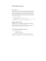
Purpose
This guide details the hardware features of the switch, including its physical and
performance-related characteristics, and how to install the switch.
Audience
The guide is intended for use by network administrators who are responsible for installing and
setting up network equipment; consequently, it assumes a basic working knowledge of LANs
(Local Area Networks).
.

T
ABLE
O
F
C
ONTENTS
Introduction
1
Features and Benefits
1
Front Panel LED’s
2
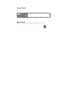
Front panel
3
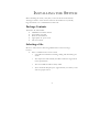
Rear Panel
3
Installing the Switch
4
Package Contents
4
Selecting a Site
4
Instructions
5
Troubleshooting
7
Diagnosing Switch Indicators
7
Cables
8
Cable Specifications
8
Product Specifications
10

1
I
NTRODUCTION
The LNES24 is a 24-port Fast Ethernet switch. The 10BASE-T/100BASE-TX
ports deliver dedicated 10/100 Mbps links to each attached LAN segment – all
with conventional cabling and adapters.
Auto-negotiation is used to select the optimal communication mode for
each connection. Auto-sensing is used to select the optimal transmission
speed for each connection. With store-and-forward switching and flow
control, maximum data integrity is always maintained, even under heavy
loading. Easy installation and reliability make this plug-and-play switch an
ideal choice for smooth Fast Ethernet integration.
Features and Benefits
• Auto-negotiation of half or full duplex, and auto-sensing of
transmission speed, on all ports
• Auto configuration for MDI/MDI-X cable connection allows
connections to servers, workstations, hubs or switches to be made
with straight-through cabling
• ANSI/IEEE 802.3u compliance ensures compatibility with
standards-based hubs, switches and cards from any vendor
• Store-and-forward switching ensures error-free transmission
• Half- and full-duplex flow control prevents packets from being
dropped under heavy loading
• Plug-and-play
• “At-a-glance” LEDs for port and system status monitoring
• Desktop and rack mountable

2
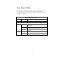
Front Panel LEDs
The front panel of the switch provides a link status LED for each RJ-45
port. In addition, the front panel also contains status LEDs for
“at-a-glance” system monitoring. The following table details the functions
of the various indicators:
Port and Switch Status LEDs
LED Condition Status
Power On Green The switch is receiving power.
Ports
On
The port has established a valid network
connection.
Flashing Traffic is passing through the port.
Link/Act
Off
The port has not established any network
connection.
On Indicates the port is operating at 100Mbps
10/100
Off Indicates the port is operating at 10 Mbps.


4
I
NSTALLING THE
S
WITCH
Before installing the switch, verify that you have all the items listed under
“Package Contents.” Note that the switch can be installed on any suitably
large flat surface or in a standard EIA 19-inch rack.
Package Contents
The Switch 10/100 includes:
• LNES24 Fast Ethernet Switch
• Four rubber foot pads
• Rack-mount bracket kit
• Appropriate AC power cord
• This User Guide
Selecting a Site
Be sure to follow the site selection guidelines below when choosing a
location:
• Select a suitable location for the switch:
o It should be accessible for installing, cabling and maintaining the
switch.
o The temperature and humidity should be within the ranges listed
in the specifications.
o The status LEDs should be clearly visible.
o There should be adequate space (approximately two inches) on all
sides for proper air flow.

5
• Make sure twisted-pair cable is always routed away from power lines,
fluorescent lighting fixtures and other sources of electrical
interference such as radios, transmitters, etc.
• Make sure that a properly grounded power outlet is within 2.44 meters
(8 feet) of the switch and is powered from an independent circuit
breaker. As with any equipment, using a filter or surge suppressor is
recommended.
Instructions
1. Positioning the Switch: For desktop or shelf mounting, attach the
four adhesive foot pads to the bottom of the switch. For rack- mounting,
attach the mounting brackets on both sides of the screws provided, and
install the switch in the rack.
2. Applying Power: Plug one end of the power adapter into the power
receptacle at back of the switch, and the other end into an appropriate
electrical outlet. Check the Power LED to be sure power is on.
Note: It is not necessary to power off the switch before connecting or
disconnecting any UTP cables, as these actions will not disrupt
the operation of other devices attached to the switch.
3. Connecting PCs: Connect each PC to an RJ-45 port on the switch
using Category 5 or 5e shielded or unshielded twisted-pair (UTP or
STP) cable, maximum length 100 meters (328 ft). LNES24 will support
up to 24 PCs. All ports on the switch support automatic MDI/MDI-X
operation, so you can use straight-through cables for all network
connections to PCs or servers, or to other switches or hubs.
Note: If an attached device does not support auto-negotiation, the data
rate will be sensed automatically and the communication mode
will default to half duplex.

6
4. Cascading Switches and Other Network Devices: All the
ports on the switch support automatic MDI/MDI-X configuration for cable
connections. This allows you to use straight-through cable to connect
to other switches or hubs from any port on the switch. No crossover
cables or other device settings are needed. See the Cable
Specifications.
Caution: Do not plug a phone jack connector into any RJ-45 port. This
the switch. Instead, use only twisted-pair cables
with RJ-45 connectors that conform with FCC standards.

7
T
ROUBLESHOOTING
Diagnosing Switch Indicators
1. Symptom
Power LED does not light after power on.
Probable Causes
o AC power cord may be defective.
Possible Solutions
o Check for loose connections.
o Check the power outlet by using it for another device.
o Replace the AC power cord.
2. Symptom
Link LED does not light after connection is made.
Probable Causes
o Switch port, network card or cable may be defective.
Possible Solutions
o Check that the switch and attached device are both powered
on.
o Be sure the network cable is connected to both devices.
o Verify that Category 5 or better cable is used for 10/100
Mbps connections and that the length of any cable does not
exceed 100 meters (328 feet).
o Check the network card and cable connections for defects.
o Replace the defective card or cable if necessary.

8
C
ABLES
Cable Specifications
Cable Types and Specifications
Cable Type Max. Length
Connector
10BASE-T
2-pair Cat. 3 or better 100-ohm
UTP
100 m (328 ft)
RJ-45
100BASE-TX
2-pair Cat. 5 or better 100-ohm
UTP
100 m (328 ft)
RJ-45
10BASE-T/100BASE-TX Pin Assignments
Caution: DO NOT plug a phone jack connector into any RJ-45 port.
Use only twisted-pair cables with RJ-45 connectors that
conform with FCC standards.
Use unshielded twisted-pair (UTP) or shielded twisted-pair (STP) cable for
RJ-45 connections: 100-ohm Category 3 or better cable for 10 Mbps
connections or 100-ohm Category 5 or better cable for 100 Mbps
connections. Also be sure that the length of any twisted-pair connection
does not exceed 100 meters (328 feet).
Because all ports on this switch support automatic MDI/MDI-X
operation, you can use straight-through cables for all network connections
to PCs or servers, or to other switches or hubs. In straight-through cable,
pins 1, 2, 3, and 6, at one end of the cable, are connected straight through
to pins 1, 2, 3 and 6 at the other end of the cable.

9
The table below shows the 10BASE-T/100BASE-TX MDI-X and MDI
port pinouts.
Pin MDI-X Signal Name MDI Signal Name
1 Receive Data plus (RD+) Transmit Data plus (TD+)
2 Receive Data minus (RD-) Transmit Data minus (TD-)
3 Transmit Data plus (TD+) Receive Data plus (RD+)
6 Transmit Data minus (TD-) Receive Data minus (RD-)
4,5,7,8 Not used at 10/100 Mbps Not used at 10/100 Mbps
Page is loading ...
Page is loading ...
Page is loading ...
-
 1
1
-
 2
2
-
 3
3
-
 4
4
-
 5
5
-
 6
6
-
 7
7
-
 8
8
-
 9
9
-
 10
10
-
 11
11
-
 12
12
-
 13
13
-
 14
14
-
 15
15
-
 16
16
-
 17
17
-
 18
18
-
 19
19
-
 20
20
-
 21
21
-
 22
22
-
 23
23


LG-Nortel ELO ES24 User manual
- Category
- Network switches
- Type
- User manual
- This manual is also suitable for
Ask a question and I''ll find the answer in the document
Finding information in a document is now easier with AI
Related papers
Other documents
-
Nortel Networks GS8MP User manual
-
-
-
-
-
Nortel Passport 8608SXE Installing
-
Nortel AL2012B45-E5 Datasheet
-
Avaya Business Ethernet Switch 50 Series User manual
-
-