Page is loading ...

VCOSI-01618-EN 15/10
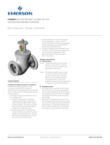
Cast Check Valves, Swing check and Tilting Disc
FASANI OPERATING AND SAFETY INSTRUCTIONS
CHECK VALVES
© 2017 Emerson. All Rights Reserved
WARNING
For safety reasons, it is important to take the
following precautions before you start work on
the valve:
1. Before installing, operating or maintaining the
valve, read all labels fitted to the valve and the
present document.
2. Use valves only for the intended purpose
(according to contract).
3. Any additional mounting/modifications and/
or accessories mounting on valves are not
allowed without approval from our technical
department.
4. Personnel making any adjustments to the
valve should use equipment and clothing
normally used to work with the process where
the valve is installed.
5. The line must be depressurized, drained,
vented and cooled down before installing the
valve.
6. Handling and installing of valves, operators
and actuators must be carried out by qualified
personnel.
7. Ensure the valve materials of construction and
pressure/temperature limitations marked on
the identification label are above or equal to
service conditions for which the valve has been
designed.
8. It is possible that some cavities within the
valve body may contain some water pockets,
for example after hydrostatic test. If the
water pockets are not drained and the valve
is subject to a temperature gradient, it is
possible that the internal pressure may
exceed the valve allowable pressure rating.
Where such a condition is possible, it is the
responsibility of the purchaser to provide,
or require to be provided for any design,
installation, or operating procedure to assure
that the pressure in the valve will not exceed
that allowed by the pressure rating of the
valve.
9. Check correct electric connection of actuator if
any. Wrong connection may cause danger and
heavily damage the valve.
10. If the actuator is required to be repositioned
on the valve, it is necessary after this operation
to recalibrate the limit switches (this operation
is described in the actuator maintenance
manual). Non-calibrated actuators may
become dangerous and may cause irreparable
damage to the valve.
INSTALLATION
1. Install the valve so that the arrow applied
on the valve body corresponds to the flow
direction of the line. For check valves, the
arrow direction corresponds to the valve
opening direction.
2. Unless specifically stated on the general
drawing, installation must be carried out
with stem in horizontal orientation (in case
of horizontal installation: with upward flow).
3. Check valves can be installed in horizontal
or vertical pipelines. The only exception is
represented by the piston check valve, ‘T’
configuration, which can be installed only on
horizontal pipelines.
4. Remove protective covers from valve end
faces and any transportation protection
applied to the valve stem (if applicable).
5. It is responsibility of the customer,
depending on the installation, to arrange
for a proper support for the valves and/or
the actuator, in particular for valves with
pneumatic actuators.
6. For flanged valves ensure that coupling
flanges and gaskets are clean and
undamaged. For buttweld valves ensure
that the weld profile is clean and in suitable
condition for welding.
7. Should there be any possibility of abrasive
particles (welding residues, sand, chemical
cleaning residues etc.) within the piping
system, this could damage valve seating.
The system needs to be thoroughly flushed
and cleaned prior to operation.
8. If valve ends are flanged, ensure that the
valve flanges and pipe flanges are aligned
correctly; bolting should be easily inserted
through mating flange holes. Tighten the
flange bolts using the crossover method.
9. Install the valve in the pipework ensuring
easy access to the operating mechanism
(handwheel, actuator) if applicable, and
ensure a stress-free installation at the valve
ends.
10. Welding and thermic treatment temperature
limitations for the valve will be stated
on the general arrangement drawing (if
applicable). Consideration must be given to
both these limitations and those indicated
on the valve nameplate. Preheat / local
thermic treatments must be performed in
Emerson.com/FinalControl
accordance with the relevant WPS/PQR and
they are under complete responsibility of
the customer.
11. All valves must be partially opened prior to
welding.

2
FASANI OPERATING AND SAFETY INSTRUCTIONS
CHECK VALVES
OPERATING AND ROUTINE MAINTENANCE
!! Read carefully this document and all
warning labels fitted to the valve before
carrying out any action on the valve !!
WARNING
• Before lifting or handling the valve, check that
there are no execution limits.
• The equipment used for valve handling and
lifting (fasteners, hooks, etc.) must be sized and
selected by taking into account the valve weight
indicated in the packing list and/or delivery
note. Lifting and handling must be made only by
qualified personnel.
• Caution must be taken during the handling to
avoid that the valve passes over the workers,
the equipment or any other place where a
possible fall could cause damage. In any case,
the local safety regulations must be respected.
• To lift the valve, hook the slings to the flange
holes or valve body holes; never lift the valve
through the actuator.
STORAGE / PROTECTION / SELECTION
State of delivery
Our valves are delivered with protection in
accordance with customer’s specification, or in
accordance with the standard Quality Control
Plan. To protect the valve ends from damage,
the original wrapping and/or covers should be
kept and removed only before installing the
valve to the pipe.
Storage
When the valves have to be stored for some
time before being installed, storage should be
in the original delivery crates with waterproof
lining and/or desiccant in a clean, dry, indoor
area.
If storage is for a period exceeding six months
the desiccant bags (if supplied) should be
substituted. If valves are stored for longer than
12 months, they should be inspected by our
personnel before installation.
Selection
Ensure the materials of construction of the
valve and pressure/temperature limits shown
on the identification plate are suitable for the
process fluid and conditions. If in doubt contact
your Emerson representative.
12. Pipeline flushing: valve materials are
usually resistant against pickling fluids
(as the pipe material is). If required, check
resistance to pickling with the pickling
company. If necessary, disassemble valve
internal parts and replace them with special
pickling inserts. Protect sensitive places
with paint or cover plates.
NOTE
Damage may occur to the valve (i.e. to the valve
seats) during high speed flushing operation, caused
by particles that could be present in the line. For this
reason, it is recommended to arrange the valve in
open position and not to perform any other actions
during pickling and flushing. The pickling process
must take place without interruptions to prevent
unnecessary impingement due to the pickling
fluid. At the end, remove pickling fluid completely.
Check with particular care the dead spaces in the
valves and the interstices between pipe sections
(perform inspection if necessary).
Replace gaskets and gland packing which have been
in contact with the pickling fluid. Carefully clean
sealing areas before replacement.
13. Check gland/pressure bolts before
operating the valve(during start up, or even
in service, the bolt tension may decrease).
14. In case of operating temperatures above
200°C (392°F), thermal insulation of the
valve body is recommended.
15. In case of insulation the valve bonnet/gland
must be maintainable.
Limitations
• Do not use valve for end-of-line function.
Standard safety practices require, for end of
line function, 2 valves or one valve plus blind
flange.
• Do not use on/off valves for control services.
• Do not use process valves as stop valves for
flushing.
• Suggested allowable max pipeline flow
velocity is:
6m/s for liquid
80m/s for gas or steam.

3
FASANI OPERATING AND SAFETY INSTRUCTIONS
CHECK VALVES
Operation
Check valves can be operated by the process
fluid of the line on which they are installed, or
by an external operator (electric/pneumatic/
hydraulic).
Actuator torque/travel switches are set at the
factory prior to shipment. They must not be
altered before valve or actuator disassembly.
In any case, these operations must be
performed by qualified and skilful personnel,
always following the instructions included in
the maintenance manuals. All the electric
connections must be performed by qualified
personnel. During this phase, the qualified
personnel must check the correct setting of
every actuator limit switch. The valve must
be operated only by the relevant operating
instrument, without using any lever or additional
wrench. During start-up of the plant check
gland packing and body/bonnet flange bolts.
Maintenance
WARNING
• Depressurize the line before starting any
maintenance. Failure to do so may cause
serious personal injury and/or equipment
damage.
• In case the valve should be removed from the
line, depressurize the line with the valves in
open position. Then, close the valve by position.
If valves are fitted with grease nipples, grease
should be applied at 3 month intervals.
Exposed threaded parts of the stem should
have grease applied at similar intervals.
Lubricate the actuator according to individual
manufacturer instructions.
No other routine maintenance is required
other than periodic inspection to ensure
satisfactory operation and sealing. Any leakage
from the gland packing should be addressed
immediately by depressurizing the valve and
tightening the gland screws gradually and
evenly.
If no further adjustment is possible or seat
leakage is suspected, the valve will require
a complete overhaul. This must be carried
out after valve or line depressurisation and
drainage in accordance with the relevant
maintenance instruction.
Spare parts
Use always original spares only.
Our valves are identified by a serial number,
which is stamped on the identification plate.
This reference should be quoted in respect of
any after sales queries, spare parts or repair
enquiries/orders.

4
Neither Emerson, Emerson Automation Solutions, nor any of their affiliated entities assumes responsibility for the selection, use or maintenance of any product.
Responsibility for proper selection, use, and maintenance of any product remains solely with the purchaser and end user.
Fasani is a mark owned by one of the companies in the Emerson Automation Solutions business unit of Emerson Electric Co. Emerson Automation Solutions,
Emerson and the Emerson logo are trademarks and service marks of Emerson Electric Co. All other marks are the property of their respective owners.
The contents of this publication are presented for informational purposes only, and while every effort has been made to ensure their accuracy, they are not to be construed
as warranties or guarantees, express or implied, regarding the products or services described herein or their use or applicability. All sales are governed by our terms and
conditions, which are available upon request. We reserve the right to modify or improve the designs or specifications of such products at any time without notice.
Emerson.com/FinalControl
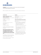
TAGPLATE REFERENCE
Pos. Description
1 Year of construction
2 Valve type
3 Nominal diameter
4 ASME class
5 N/A
6 Body material
7 Stem
8 Seat face material
9 Disc face material
10 Designed code
11 Room temperature
12 Pressure at room temperature
13 Pressure Shell Test
14 Differential pressure set up actuator
15 Min. allowable temperature
16 Pressure at min. allowable temperature
17 Max allowable temperature
18 Pressure at max. allowable temperature
19 N/A
20 N/A
21 Serial number
22 Ped category
23 Fluid
24 N.A
25 Tag
26 Order number
27 N/A
FASANI OPERATING AND SAFETY INSTRUCTIONS
CHECK VALVES
/