Firecraft P30G FXL01 User manual
- Category
- Fireplaces
- Type
- User manual
This manual is also suitable for

INSTALLATION AAND UUSER
INSTRUCTIONS
All iinstructions mmust bbe hhanded tto uuser ffor ssafekeeping
Revision B - 10/05
Country(s) of destination - GB/IE
FLUELESS GGAS FFIRE
RANGE
BLENHEIM SSTYLE
ELEGANCE
LULWORTH
ASPEN
Focal Point Fires plc, Avon Trading Park, Christchurch, Dorset BH23 2BT
Tel: 01202 499330 Fax: 01202 499326
www.focalpoint.co.uk
e-mail: [email protected]

Blenheim Style
Elegance
Lulworth
Aspen

INSTTALLATTION IINSTTRUCTTIONS
PPrreelliimmiinnaarryy NNootteess BBeeffoorree IInnssttaallllaattiioonn
This is a High Efficiency, Flueless, Inset Live Fuel Effect appliance. It provides radiant and con-
vected warmth both efficiently and safely utilising the latest type catalytic converter burner
technology.
This fire incorporates a combustion monitoring system (Oxygen Depletion Sensor). It must
not be adjusted or put out of operation. If replaced then manufacturers original parts must be
used. The fire is designed to fit various types of situations as listed in the Installation
Requirements.
This appliance must be installed in accordance with the rules in force and only used in a suf-
ficiently ventilated space.
A minimum of 100cm
2
(15.5 in
2
)
purpose provided ventilation is
required for this appliance, an openable window or louvre is also required. This appliance is
factory set for operation on the gas type, and at the pressure stated on the appliance data
plate.
The room size should be a minimum of 30m
3
(1059ft
3
) to allow adequate circulation of air and
ensure the correct operation of the fire when installed in a living room. This volume may
include adjacent spaces but these spaces must not be separated by a door. In order to con-
vert from cubic feet (ft
3
) to cubic metres (m
3
) divide the room volume (in ft
3
) by 35.3. This
appliance is intended as a secondary source of heat only, and should not be used in a room
without some form of background heating present.
The appliance must not be installed in a bedroom, bathroom or any sleeping area. The appli-
ance does not require a flue system of any type as the catalytic converter cleans the com-
bustion products to provide a complete combustion system which is intrinsically safe.
The appliance must be installed by a competent person in accordance with Gas Safety
(Installation and Use) Regulations 1998 or rules in force. It is strongly recommended that a
CORGI registered engineer is used for this purpose as they are the only persons approved by
the HSE under the above regulations.
On initial lightup of a new appliance, the ‘newness’ smell will burn off within the first few
hours of operation. During this period some smoke may be emmited from outlet louvres, this
should be no cause for concern. Accordingly, the room should be well ventilated during this
period.
Read all these instructions before commencing installation.

IMPORTANT NNOTES
This fire is an Inset Live Fuel Gas Fire, providing radiant and convected warmth. It is designed to operate on
Natural Gas following factory set adjustments, (see Data Plate on appliance for gas type and pressure).
It is the LAW that all gas appliances and fittings are installed by a competent person (such as a CORGI registered
fitter) and in accordance with the Gas Safety (Installation and Use) Regulations 1998, the relevant British
Standards for Installation, Codes of Practice and the Manufacturers' Instructions. The installation shall also be
carried out in accordance with the following regulations:
The Building Regulations issued by the Department of the Environment, the Building Standards (Scotland)
(Consolidation) Regulations issued by the Scottish Development Department.
Relevant BBritissh sstandardss iinssofar aass tthe rrelevant aareass aare nnot ccovered bby tthesse iinsstrucctionss.
Note: FFor RRepublicc oof IIreland, rreferencce sshould bbe mmade tto tthe rrelevant sstandardss ggoverningg iinsstallation. ((IS
813: 11996))
Failure to comply with these regulations could lead to prosecution and deem the warranty invalid.
This appliance must be installed in accordance with the rules in force and used only in a sufficiently ventilated
space. A minimum of 100cm
2
(15.5 in
2
) purpose provided ventilation is required for this appliance, an openable
window or louvre is also required. To reduce the possibility of draughts entering the room via the air vent, we
recommend the use of "Black Hole" or "Vortex" type vents featuring internal baffles.
It should be noted that heaters create warm air currents. These currents move heat to wall surfaces next to the
heater. Installing the heater next to vinyl or cloth wall coverings or operating the heater where impurities in the
air (such as tobacco smoke) exist, may discolour walls.
Consult ALL instructions before installation and use of this appliance.
This appliance is free from any asbestos material. Refractories and coal bed are constructed from ceramic fibre.
1
Secction Contentss Pagge NNo.
1.0 Important NNotes 1
2.0 Appliance DData 2
3.0 Installation RRequirements 2
3.1 Room Sizing 2
4.0 Site RRequirements 2
4.1 Ventilation 3
5.0 Unpacking tthe AAppliance 4
5.1 Component Checklist 4
6.0 Appliance IInstallation 4
6.1 Preparing the Appliance 4
6.2 Gas Supply Routes 5
6.3 Installation Method 1 5
6.4 Installation Method 2 6
6.5 Installation Method 3 7
7.0 Gas SSupply 8
8.0 Final CCavity BBox FFixing 8
Secction Contentss Pagge NNo.
8.1 Cable Fixing 9
9.0 Fuel BBed 99
10.0 Fitting DDecorative HHood/Frame 10
11.0 Testing aand CCommissioning 10
11.1 Operating the Appliance 10
11.2 Spark Failure 11
11.3 Setting Pressure 11
12.0 Briefing tthe CCustomer 11
13.0 Servicing 11
13.1 Cleaning the Coals 12
13.2 Servicing the Burner Tray 12
13.3 Pilot Assembly 12
13.4 Catalytic Converter 12
13.5 Testing for Firebox Leakage 13
14.0 Troubleshooting GGuide 14
User IInstructions
1.0

INSTALLATION RREQUIREMENTS
The fire has been designed to be installed in two main applications; either to fit into a suitable opening created
in the inner leaf of an outside wall or false chimney breast/extended fire surround built to conceal the appliance.
The appliance can also be fitted into an unserviceable or inoperative fireplace served by a disused natural
draught flue. It is recommended that the old flue should be partially sealed off to prevent draughts, however
some ventilation will be required in the old flue to prevent condensation and dampness.
The cavity box and firebox must be installed onto a suitable non-combustible insulating surface at least 12 mm
thick covering the entire base area of the box. The fire must be used with a back panel capable of withstanding
150°C minimum. Any combustible materials directly behind the fire frame (or back panel) and close to the cav-
ity box of the fire must be removed and replaced with non-combustible material such as cement, browning,
'Superlux' board or equivalent materials.
ROOM SSIZING
The room size should be a minimum of 30m
2
(e.g. 11’6” x 11’6” x 8’) to allow adequate circulation of air and
ensure the correct operation of the fire. To calculate a room size in cubic metres (m
3
) divide the room volume
in cubic feet (ft
3
) by 35.3.
SITE RREQUIREMENTS
The appliance may be installed by one of the following methods:
1. Fitment against the inner face of a house wall with a suitably constructed false chimney breast or
rebated fire surround to enclose the depth of the fire. If a timber false chimney breast is construct
ed, clearances and insulation must be as for a timber constructed wall.
2. Insertion into a purpose made opening in the inner leaf of a cavity wall or a disused conventional
fireplace opening. Bridging the cavity may cause unwanted moisture to track to the inside of the
house from the cavity and therefore should be avoided. Protection from moisture and falling debris
above the cavity box should be provided. If in doubt consult local building control officers.
3. Installation into a timber framed house wall using clearances and insulation as described in the
appropriate section. If in doubt, consult local building control officers.
The opening dimensions for insetting the appliance must be;
WIDTH ::
between 410 mm and 440 mm and
HEIGHT ::
between 560 mm and 580 mm high. The opening must be within these sizes for the full depth of the
cavity box in non-combustible applications. Applications involving combustible materials e.g. timber battens in
false chimney breasts, must use appropriate clearances and insulation methods as described in the relevant sec-
tion of these instructions.
2
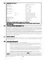
APPLIANCE DDATA
Gas Group G20 Natural Gas CAT I2H
Inlet Pressure 20 mbar
Max Energy Input Gross 2.6 kW
Net 2.35 kW
Max Gas Rate 0.25 m3/h
Min Energy Input Gross 1.5 kW
Net 1.35 kW
Pilot Energy Input Gross 166 W
Net 150 W
Setting Pressure High 7.0 mbar (+/-0.25 mbar). Cold
7.5 mbar (+/-0.25 mbar). Hot
Low 2.0 mbar (+/-0.25 mbar). Cold
2.8 mbar (+/-0.25 mbar). Hot
Main Injector Burner Stereo. Size 60 / Bray Cat 82 - 280
Gas Inlet Connection 8 mm compression
Ignition Piezo spark
Spark Gap 4.0 mm (± 1.0mm)
Weight 20 Kg
Please ssee DData BBadge aaffixed tto aappliancce ffor ccurrent ddata.
This aappliancce iis ffor uuse oonlyy wwith tthe ggas ttyype, aand aat tthe ppressure sstated oon tthe aappli-
ancce DData BBadge.
2.0
3.0
3.1
4.0

SITE REQUIREMENTS (continued)
Opening
DEPTH
must be 145 mm or greater. Opening
DEPTH
includes any plaster, cement or infill/back pan-
els that form part of the installation.
In the event that the fire is sited in a disused or unserviceable fireplace served by a natural draught flue, any exist-
ing under grate draught device should be sealed off to prevent loss of heat or creation of draughts. The pas-
sageway into the flue should be partially sealed to prevent excessive draughts, however some ventilation will be
required in the old flue to prevent condensation and dampness. Advice should be sought from your local build-
ing control officer.
If a concealed gas connection is to be made, the supply pipe should always be sleeved through walls and floors
using the shortest possible route. It is possible to install the gas supply from the side of the hearth and round into
the cavity but use only factory sleeved pipe. A length of no more than 1.5m of 8mm diameter pipe must be used
to avoid unnecessary pressure drops.
The wall for the opening must be non-combustible or prepared as described in the relevant section. Bare plas-
terboard must be protected by non-combustible plaster or replaced with non-combustible material (e.g. Superlux
board). Any gap between wall boards and the wall must be filled using glass fibre insulation, silicone mastic or
similar material to prevent heat ingress.
If the appliance is to be installed as a 'hole in the wall' fire it does not require any hearth as such, providing it is
mounted more that 150mm (6") above floor level. NOTE: Depending on the fret and trim type supplied with the
fire, a suitable non-combustible ledge for placement of the fire front will be required.
The appliance requires a hearth with a non-combustible surface of at least 12 mm thick, projecting 100mm from
the front of the appliance. The top surface must be at least 50 mm above the surrounding floor level or be sur-
rounded by a raised edge or fender 50 mm high.
Any type of fire surround used with this appliance must be adequately sealed to the wall and floor to prevent
excess draughts from around the back of the fire. The temperature rating of any surround used must be 150°C
minimum.
A combustible shelf may be fixed to the wall above the fire, providing that it complies with the dimensions given
below.
The shelf depth may be greater but the height must also be increased accordingly. An increase in height of 25
mm is required for every 12.5 mm of additional shelf depth. For shelves that are too low protective devices can
be used such as metal heat deflectors, but it must be assured that the shelf does not reach an unacceptable tem-
perature before relying on such a solution. A non-combustible shelf may be fitted to within 100mm of the top
edge of the fire frame, but any articles placed on it must also be tolerant of high temperatures.
Combustible materials such as wood may be fitted to within 100mm (4in) of either side of the fire frame / trim,
providing the forward projection does not exceed 100mm (4in). Any combustible sidewalls must be at least
500mm to the side of the radiant heat source.
As with all heating appliances any decorations, soft furnishings and wall coverings (i.e. flock, blown vinyl and
embossed paper) positioned too close to the appliance may discolour or scorch.
VENTILATION
A minimum of 100 cm
2
purpose provided ventilation is required for this appliance. An openable window or lou-
vre is also required. The requirements of other gas appliances operating in the same room or space must be
taken into consideration when assessing ventilation. It is recommended that the appliance should not be
installed within 500mm of any air vent.
Any ventilation fitted must comply with BS 5871 part 2 and BS 5440 part 2 insofar as the relevant areas are not
covered by these instructions. Ventilation fitted under or within immediate vicinity of the appliance must not be
used as it may adversely effect performance of the ODS system. The appliance MUST NOT be installed in a bed-
room, bathroom or any sleeping area. For Republic of Ireland, see relevant rules in force.
3
Maximum ddepth oof sshellf MMinimum ddistancce ffrom hhearth tto uunderside oof sshelf
180mm 850mm
100mm 790mm
4.0
4.1

UNPACKING TTHE AAPPLIANCE
Stand the carton the right way up, cut the strapping bands and remove the top endcap. Read ALL these instruc-
tions before continuing to unpack or install this appliance.
Remove the box containing the cast front fret, and the box containing the ceramic coals and other ceramic
firebed components. Remove the cardboard packing pieces and any other bags or boxes containing fittings or
other parts. When all loose parts have been removed, the outer sleeve may be lifted off to reveal the appliance.
Check that the components supplied against the component checklist. Please dispose of all the packaging mate-
rials at your local recycling centre.
COMPONENT CCHECKLIST
QUAANTITY DESCRIPTION
1 Cavity box, firebox and burner assembly fitted with glass panel
1 Decorative frame
1 Hood
1 Cast front fret with separate ashpan door
1 Moulded ceramic fibre combustion fuel bed
1 Ceramic pad set
1 Sealing grommet
1 Cable fixing kit
1 Screw and rawl plug pack
1 Set of manufacturers instructions
APPLIANCE IINSTALLATION
Note: EEnssure tthat tthe ggass ssupply iiss iissolated bbefore ccommenccingg iinsstallation oof tthe aappliancce.
The fireplace opening and environment must be in compliance with specifications laid down in the appropriate
sections of these instructions.
PREPARING TTHE AAPPLIANCE
Remove the appliance from its carton as described previously and stand on a dustsheet. Remove the glass panel
and place it and the coals, ceramics and fixings safely to one side.
Lay the fire on its back. Remove the firebox assembly from the cavity box by removing the fixings provided on
the front of the firebox frame. Place the firebox to one side for the time being.
Knock out holes are provided in the rear and sides of the cavity box for use where concealed pipework is
required. Note: Knock out holes are also provided in the sides of the inner firebox if a side-entry pipe routing is
required, but it is not necessary to seal these holes with gromments. Knock out the appropriate hole in the cav-
ity box with a sharp tap from a hammer and fit the rubber grommet supplied. A small incision can now be made
in the rubber to slip snugly around the outside of the supply pipe and sleeving.
Note: DDo nnot iinsstall oor uusse tthe aappliancce wwithout tthiss sseal iin pplacce.
4
5.0
5.1
6.0
6.1

GAS SSUPPLY RROUTES
The gas supply may enter the fire over the hearth or by concealed connection behind the fire.
Following preparation of the fixing method, the concealed gas supply (if required), can now be installed.
When the opening is ready for installation the gas supply can be routed. If the gas pipe has been sleeved the
ends of the sleeving must be sealed. The end of the 8mm pipe should be temporarily sealed to prevent the
ingress of debris during fixing.
An isolator cock or or restrictor elbow must be fitted to the incoming supply to facilitate servicing.
Concealed pipes should not be routed through walls without being protected by sleeving or conduit.
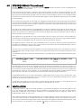
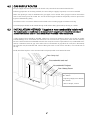
INSTALLATION MMETHOD 11 ((against aa nnon-ccombustible iinside wwall)
Thiss mmethod rrequiress nno mmodificcationss tto tthe iinternal wwall oof aa pproperty aand iiss aacchieved bby uussingg eeither aa
ssurround wwith eextended rrebate oor aa ffalsse cchimney bbreasst oof mminimum 1145mm iinternal ddepth.
A false chimney breast should be installed, taking into account any guidance given in the section on timber
framed buildings as far as insulation and clearances are concerned. As a general rule, when the false chimney
breast is constructed from combustible materials the cavity box must be separated from any combustible mate-
rials by a minimum 75mm air gap at the sides and rear and 100mm air gap above the cavity box. Alternatively
the cavity box may be insulated with 75mm of fibre glass wool or rock wool to the sides, rear and 100 mm to
the top.
Finally install the fireplace or fire surround and back panel/marble to its finished location.
5
A- Opening Width; Max 440mm,
Min 410mm
B- Opening Height; Max 580mm,
Min 560mm
C- Recess Depth; 145mm
Outer Cavity Leaf
Non-combustible Backpanel
False Chimney Breast
A
B
C
6.2
6.3
Non-combustible inside wall

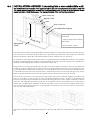
INSTALLATION MMETHOD 22 ((recessing iinto aa nnon-ccombustible wwall)
Thiss mmethod aallowss ffor iinsstallation oof tthe aappliancce wwith tthe rrear ppart rreccessssed iinto tthe iinner lleaf oof aa ccavity wwall.
Thiss sshould eenable aa sstandard ffire ssurround aand bbacck ppanel/hearth sset tto bbe ffitted tto tthe wwall wwith tthe ffire ppre-
ssented nnaturally iin aa fflussh ffitted mmanner. TThe sstrucctural iinteggrity oof tthe wwall mmusst bbe mmaintained.
Check the cavity insulation type (if applicable). If cavity insulation is of a loose fill variety, take precautions to pre-
vent excessive loss of material when the inner leaf is opened up by packing the cavity firmly with a minimum
50mm of rockwool or glass fibre. This will hold back any loose material now or in the future.
To maintain the structural integrity of the wall it is recommended that a suitable lintel is fitted. It is sometimes
possible to install this appliance without a lintel, depending on the type of wall. The guidance of a qualified pro-
fessional or local building control officer is essential to confirm this.
Mark out the area of the proposed fireplace opening on the wall. Obtain a suitable concrete or steel lintel from
a builder's merchant. Drill four holes at the corners of the lintel position and squarely over the fireplace open-
ing, and if possible centrally under a block joint . Clear out the block work in the area and insert the lintel by saw,
or stitch drill and chisel. Do not dry bed the lintel - always bed on mortar and securely slate pin. Clear out the
block work from below the lintel to form the opening for the cavity box of the fire to be inserted.
The top of the exposed area of cavity must be sealed against the ingress of moisture dripping from above. The
best way to do this is a cavity tray but an easier and quicker method is to affix a 'Supalux' or equivalent board
into the cavity. Slope the board towards the outside wall and support with screws, cement, 'Unibond' or silicone
mastic etc. This will guide all moisture, harmlessly, to the outside wall. The exposed sides of the cavity must be
packed with a suitable depth (minimum 50mm) of glass fibre or rock wool to prevent draughts and heat loss,
even if no loose fill material is present. It is good practice to insulate the rear of the fire from the cavity to pre-
vent heat loss and condensation.
The non-combustible hearth may now be put in place. Again this should not bridge the cavity where it proj-
ects into the wall space. Finally install the fireplace or fire surround and back panel/marble to its finished loca-
tion.
6
A- Opening Width; Max 440mm,
Min 410mm
B- Opening Height; Max 580mm,
Min 560mm
C- Recess Depth; 145mm
Outer Cavity Leaf
Superlux Board
Lintel
Inner Cavity Leaf
Non-combustible Backpanel
Superimposed
Hearth
B
A
C
6.4

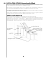
INSTALLATION MMETHOD 33 ((timber fframed bbuildings)
Where removal of any part of a timber frame is undertaken the structural integrity of the wall must be retained.
The advice of your local building control officer should be sought. If the property is under any NHBC warranty
it is also advised that their advice on this kind of modification is sought.
Either of the two preceding installation methods may be adapted for timber framed buildings, providing extra
care is taken in ensuring combustible materials are adequately protected from the effects of heat.
The appliance must be installed in accordance with the British Gas documents DM2 and DM3 or the Institute
of Gas Engineers published procedure document IGE/UP/7.
Special attention must be paid to the location of studwork frames of the inner leaf and the appliance positioned
accordingly. Wires and pipes that run within the wall must also be taken into account.
Insstallation aass pper mmethod 11 ((aggainsst iinner wwall))
When using this method of installation the following amendments should be incorporated.
A 75mm air gap or 75mm of insulation (e.g. rockwool) must be provided between combustible materials and
the sides and rear of the cavity box. A 100 mm air gap or 100mm of insulation (e.g. rockwool) must be provid-
ed to the top of the cavity box. It is also a good idea to enable as much airflow as possible, into and out of the
area behind the fire without excessive heat loss from the room when the fire is off.
7
Outer Cavity Leaf
Rockwool Insulation 75mm
sides and rear 100mm top
Inner Cavity Leaf
Non-combustible
Backpanel
Cavity Box
6.5
Superimposed Hearth

INSTALLATION METHOD 33 ((continued)
Insstallation aass pper mmethod 22 ((reccessssingg iinto aa wwall))
When setting the appliance into the wall find a suitable position between frame timbers and open up the hole.
Secure back the damp proof membrane to prevent ingress of damp.
Again 50mm insulation plus a 12 mm thick fire retardant board, 'Superlux' or equivalent, must be provided
between combustible materials and the sides and rear of the cavity box. 100 mm of insulation plus a 12 mm thick
fire retardant board, 'Superlux' or equivalent, must be provided to the top of the cavity box. The exposed cavity
should be sealed off using non-combustible board, ('Supalux' or equivalent), made into a 4-sided box. It is also
good practice to further insulate the cavity with a 50mm layer of Rockwool outside the Superlux box. Note that
the appliance should not be allowed to bridge the cavity in this installation method. It is also a good idea to
enable as much airflow as possible, into and out of the area behind the fire without causing excessive heat loss
from the room when the fire is off.
GAS SSUPPLY
When the opening is ready for installation of the fire the gas supply can be routed via knockout holes. Examples
are shown in the diagram in section 6.2.
Temporarily fit the cavity box and offer up the firebox assembly to ensure a suitable gas route can be achieved.
FINAL CCAVITY BBOX FFITTING
If not previously carried out, insert the cavity box into the opening and mark the screw locations required for fix-
ing. Remove the cavity box and drill the previously marked holes in the opening or constructional hearth area
and fit rawl plugs.
Carefully insert the cavity box into the opening and guide the gas pipe through the sealing grommet into its final
routing position and fit the restrictor inlet elbow supplied to the gas pipe. Secure the cavity box by inserting
screws in the previously prepared locations.
The cavity box may also be fitted using the cable fixing kit supplied as detailed in the next section.
8
50mm Rockwool to Insulate Cavity
Superlux Box: 12mm thick, External
Dims; Height 670mm, Width
529mm, Depth 207mm
Rockwool Insulation 50mm
sides and rear 100mm top
Inner cavity Leaf
Outer Cavity Leaf
Fireplace Backpanel,
non-combustible
Cavity Box
6.5
7.0
8.0

CABLE FFIXING
When using this method for fixing, the minimum depth of the open-
ing must be increased from 145 mm to 175 mm. This is to allow for
the eyebolts and a space for the cable tensioning.
Drill four holes as shown in the diagram and fit the fibre rawlplugs.
If the fireplace does not allow for the exact layout shown, the eye-
bolts should be fixed to give as similar a configuration as possible.
Thread both tensioning cables through the holes at the top of the
cavity box then through both eyelets and back through the lower
holes in the cavity box.
Push the cavity box back into the fireplace, centralise, pull the loose
cables through the holes and into the bottom of the cavity box.
Thread the cable tensioners onto the cables with the nuts screwed
down close to the tensioner head. Slide the screwed nipple onto
the cable, pull cable taut and tighten nipple. Adjust tensioner using a suitable spanner to pull the appliance back
into position, to allow an even pull around the fireplace opening. Visually inspect and repeat if necessary to
achieve a good fit.
Note: SSurpluss ccable MMUST NNOT bbe ccut ooff, aass tthiss wwill pprevent pproper iinsstallation aafter sserviccingg. CCoil uup tthe
ssurpluss ccable aand ttucck tthe ccoilss oout oof tthe wway.
Fit the firebox assembly into the cavity box securing with the fixings originally removed. Purge the gas supply
thoroughly to remove any air or grains of dirt. Now connect the restrictor elbow to the inlet pipe of the fire
tray and tighten the gas connection. Pressurise the gas supply and test properly for soundness in accordance
with current Approved Codes of Practice.
FUEL BBED
For Elegance, Aspen and bleniem style models the fuel bed
is coloured black. For Lulworth models the fuel bed is
coloured grey. Both types are fitted in the same way.
Place the brick panel against the rear of the firebox.
Place the ceramic combustion fuel bed onto the burner
tray. Ensure that the hole for pilot flame viewing is clear
and easily visible.
9
380 mm
200 mm
80 mm
8.1
9.0

FUEL BED (continued)
Fit the glass door assembly with the 4 screws provide in the posi-
tions indicated. Ensure that the screws are tightened so as to
achieve a good seal between the glass frame gasket and the fire-
box.
The fire is designed to operate correctly with the supplied com-
ponents according to the instructions. Never add coals. Never
put combustible or non-combustible materials, rubbish or other
matter into the fire. Please note that it takes approximately 15 min-
utes for the full flame effect to be achieved.
FITTING TTHE DDECORATIVE FFRAME
AND HHOOD
The appliance is supplied with a decorative frame and hood.
The frame attaches to the firebox using either four mag-
netic pieces, or as a three piece clip-on assembly. The side
pieces of the clip on assembly should be pushed into posi-
tion first, followed by the top bar, which should overlap
the sides. For the single piece assembly, magnets should
be fitted to the steel backing plates. A plastic protective
coating may be applied to the face of the frame assembly,
which should be removed at this stage.
IMPORTANT : Due to the possibility of sharp edges, care
should be taken when handling the three piece frame
components. The use of protective gloves is recommend-
ed.
Place the firefront into position in front of the fire and slide
the ashpan door into place. Do not use any other firefront
other than the one supplied with this appliance. The fire-
front shown in these instructions may differ form the one
supplied with the appliance.
Fit the convector hood to the firebox by engaging the two mounting hooks into the relevant slots in the firebox.
The hood should be pressed inwards and downwards to secure into position.
TESTING AAND CCOMMISSIONING
As previously mentioned, firstly turn on and test the gas supply up to the fire for any leaks, in accordance with
current Approved Codes of Practice (ACOPs).
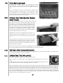
OPERATING TTHE AAPPLIANCE
The pilot is visible through the left hand side of the matrix.
Push in and turn the control knob to the SPARK position, and hold there for a few sec-
onds.
Continue turning anti-clockwise through the spark click to the PILOT light position, ensur-
ing the pilot has lit. If not, return the knob clockwise, and repeat.
When the pilot lights after the spark, keep the knob depressed for approximately ten seconds. Now release the
knob and the pilot should stay alight. If the pilot extinguishes during use, wait three minutes before repeating the
ignition procedure. To achieve the HIGH setting, push the control knob in slightly and continue turning anti-
clockwise to the high position. The main burner should light after a few seconds. To decrease the setting to LOW,
turn the control knob clockwise to the low setting.To turn to the PILOT position from the HIGH or LOW posi-
tions, press the control knob in, and return to the pilot position and release. To turn the fire OFF, keep the knob
pressed in, return to the off position and release.
10
9.0
10.0
11.1
11.0

SPARK FFAILURE
The gap between the spark electrode and the pilot should be 3 - 5mm to produce a good spark. There should
be no need to adjust this. If under any circumstances the piezo electric spark fails, the pilot cannot be lit man-
ually.
SETTING PPRESSURE
To commission the appliance, the burner pressure must be in
accordance with the figures stated in the data section of these
instructions.
The mainfold pressure test point is located on the main injector
pipe, to the left of the control plate.
Release the mainifold pressure test point screw, situated on the
left above the control knob, and attach a U gauge. Light the fire
and turn to the HIGH setting.
The burner pressure should be in accordance with the figures stated in the data section of these instructions.
The fire is factory set to achieve these pressures and any significant variation could indicate a supply problem. If
the pressure is too high, the gas supply meter may be set incorrectly. This should be checked with the fire run-
ning and if necessary reset by the gas supplier.
If the burner pressure is too low, check the meter governor pressure with the appliance running. If this is less
than 20mbar ± 2mbar it will need to be reset by the gas supplier. If the setting pressure is too low but the meter
pressure is acceptable, then a problem in the supply pipework is to be suspected. This will be dirt and debris,
kinked or inadequate size pipes, restriction in a fitting, shut off elbow not fully open or solder flashing across a
joint. Switch the fire off, disconnect the manometer and refit the test nipple screw. Light the fire and check for
gas soundness.
In the event that the burner pressure is not in accordance with the figures stated in the data section of these
instructions, the appliance must not be commissioned, and the manufacturer should be contacted for guidance.
BRIEFING TTHE CCUSTOMER
All instructions must be handed to the user for safekeeping. Show the customer how to light and control the fire.
After commissioning the appliance, the customer should be instructed on the safe use of the appliance and the
need for regular servicing. Frequency of service depends on usage, but MUST be carried out at least once annu-
ally. Advise that cleaning of the fire maybe achieved when the fire is cold using a damp cloth and mild detergent
on most surfaces. Advise that the fire will emit a "newness" smell for a time after initial commissioning and that
extra ventilation may be needed during this time. Recommend that a guard be used for the protection of young
children, pets, the elderly and the infirm.
SERVICING
Isolate the fire from the gas supply. Ensure that the fire is fully cold before attempting service. A suggested pro-
cedure for servicing is detailed below. For specific servicing instructions, see relevant sections.
1. Lay out the dustsheet and tools.
2. Remove the hood and front fret.
3. Remove the glass door assembly (4 screws) and clean carefully.
4. Carefully remove the ceramic components.
5. Inspect the catalyst and clean if necessary with a soft brush.
6. Disconnect the gas supply and remove the two securing screws in the tray legs.
7. Lift away burner tray assembly.
8. Strip off the burner pipes and clean thoroughly.
9. Clean the injector, pilot assembly and the burner tube. Do not attempt to remove the pilot injector.
10. Re-assemble and re-fit the burner tray.
11. Turn on the gas supply and leak test. Check pilot and burner for good ignition.
12. Refit the ceramics as per these installation instructions.
13. Refit the glass door assembly, ensuring a good seal.
14. Refit the hood.
15. Check any purpose provided ventilation is un-obstructed.
16. Light the fire and test setting pressures.
17. Check safe operation of the appliance.
11
11.2
12.0
13.0
11.3

CLEANING TTHE CCERAMICS
Remove the fire front and place to one side. Remove the hood. Remove the glass door assembly. Remove the
ceramic components. Gently clean in the open air with a soft brush. Be careful not to create dust from the
ceramics. Where necessary replace damaged components with genuine spares. Seal scrap ceramic compo-
nents in plastic bags and dispose at proper refuse sites as directed. If using a vacuum cleaner a HEPA filtering
system is recommended.
Re-fit the ceramics by referring to the relevant section of these instructions. Refit the glass door assembly ensur-
ing a good seal. Refit the hood.
SERVICING TTHE BBURNER TTRAY AAND GGAS AASSEMBLY
Firstly, remove the hood and front fret, the glass panel and ceramics, and disconnect the gas connection at the
isolator elbow. Remove the burner tray by removing the 2 securing screws through the legs. The gas connec-
tions to the gas valve can now be released. Remove the pilot and main burner pipes and blow through to dis-
lodge any debris. Remove the injector elbow and blow through to make sure it is entirely clear.
When replacing the injector elbow, ensure that it aligned accurately with the centre of the mixer tube entering
the burner and is not at an angle. Always make sure that the nut securing the injector elbow is tight. Unclip the
pilot lint gauze and clean with a soft brush. Clean the exterior of the pilot assembly with a soft brush and blow
through the flame ports on the pilot head. Check the aeration holes are free from lint or dirt. The pilot assem-
bly can be removed if required, by disconnecting the electrode lead, gas pipe and unscrewing the mounting
screws and lifting away.
The pilot assembly is a non-serviceable item and should not be taken apart. Aeration holes must be absolutely
clear internally for proper operation.
The gas valve is a non-serviceable item. If this needs replacement, remove the two M5 securing screws and
remove the complete valve. Replacement must be done using original manufacturers parts.
Re-assembly in the reverse of removal.
PILOT AASSEMBLY
Remove the burner tray as detailed in the relevant section and pilot unit as described. Clean the pilot assembly
with a soft brush and blow through. Check the aeration holes are free of any dirt or lint. Clean thoroughly inter-
nally. The connection can be removed from the base of the pilot unit using two spanners to make cleaning eas-
ier. Do not damage or try to remove the pilot injector.
The unit is factory set and the only check necessary is to ensure the spark gap is correct. See specifications for
gas setting.
NEVER MMODIFY OOR BBEND TTHE TTHERMOCOUPLE TTO MMAAKE TTHE PPILOT SSTAAY AALIGHT
. If the pilot will not stay
lit there is a problem with dirt, the gas supply, or the thermocouple needs replacement. Modifications are dan-
gerous and can have a serious unseen effect on safety and therefore MUST not be done. Replacement must be
done using original manufacturers parts.
CATALYTIC CCONVERTER
It is recommended that the catalytic converter is inspected for signs of damage and dirt during routine servicing
procedures. The expected life of the catalyst is in excess of 11,000 hours (10 years of normal use). After this time
the catylitic converter should be replaced.
If there are any deposits of dirt or soot on the catalyst they should be cleaned with a soft brush and a vacuum
cleaner. If removed for cleaning ensure the seals are in good condition before replacing the catalytic converter.
New seals will usually be required.
The performance of the catalyst may be checked using an analyser as follows. Any analyser used should con-
form to BS7927 : 1998 + A1 : 1999.
Important: TThe ttemperature oof tthe ggassess eemmited bby tthe ccatalyticc cconverter iiss iin eexccessss oof 4400
o
C. MMeassuringg
ggass oof tthiss ttemperature mmay ddamagge ssome ttypess oof ggass aanalysserss. IIf iin ddoubt cconssult tthe eequipment mmanufacc-
turer.
12
13.2
13.3
13.1
13.4

CATALYTIC CONVERTER ((continued)
Position gas sample probe directly over the catalyst via the outlet louvre, in the centre of the upper firebox. Ignite
the fire as per the operating instructions, and run at high setting for 15 minutes. Record the carbon dioxide (CO2)
concentration and then the carbon monoxide (CO) concentration as displayed by the analyser - also
noting the units in which the values are expressed.
Most analysers display carbon dioxide (CO2) concentrations in percentage (%) terms and carbon monoxide
concentration in parts per million (ppm) terms.
In order to calculate the combustion ratio for the appliance (CO/CO2) it is first necessary to express both gas
concentrations in terms of percentage. To convert from parts per million (ppm) to a percentage (%) divide the
ppm figure by 10,000. Examples : 35ppm = 0.0035, 15ppm = 0.0015%, 5ppm = 0.0005%.
Now divide the concentration of carbon monoxide (CO) expressed in percent by the concentration of carbon
dioxide (CO2) to obtain the appliance combustion ratio.
The ccombustion rratio oof tthe ggasses eemitted bby tthe ccatalytic cconvertor sshould nnot eexceed 00.0015.
If replacing the catalytic converter, remove the hood and front fret, then the glass panel. The catalytic converter
retaining clamp is secured with 4 nuts and slip proof washers, located on the inside of the firebox, at the top,
remove these nuts and the clamp can be removed. Withdraw the clamp, followed by the catalytic converter and
its seals from the firebox and discard.
Refit a new catalytic converter
and
seals in reverse order.
TESTING FFOR FFIREBOX LLEAKAGE
Appliances that are several years old or have been extensively dismantled should be checked for soundness. It
is important that all the products of combustion pass through the catalytic converter at the top of the firebox
before leaving the appliance.
The firebox is heated by lighting for a few minutes to provide a flow through the firebox and catalytic converter.
The burner is then shut off and a smoke pellet or match introduced at the base of the fire underneath the burn-
er tray. Large quantities of smoke will emerge from the top of the appliance but none should emerge from
around the door. It is important to note that the appliance can never be expected to be 100% smoke tight and
small quantities of smoke may be seen in corners of joints and mating faces etc without affecting safety when
the fire is actually in operation.
13
13.4
13.5
CO (%)
CO2 (%) = ratio

TROUBLESHOOTING GGUIDE
Fire ssparkss bbut ppilot ddoess nnot lligght
No gas to fire - check isolators are open.
Pipe work blockage or kink - rectify.
Air not fully purged - re-purge supply or wait longer.
Spark earthing to metal work - check gap is correct.
Blocked pilot - check and replace where necessary.
Pilot lligghtss bbut tthen ggoess oout
Severe restriction in gas supply - clear obstruction.
Faulty thermocouple - replace pilot unit.
Blocked pilot - replace.
Blocked lint gauze - clean.
Hold control knob in for longer.
Check the control knob does not foul on the data plate.
If the pilot will not stay lit there is a problem with dirt, the gas sup-
ply, or the thermocouple is in need of replacement. Modifications
are dangerous and can have a serious unseen effect on safety.
NEVER MMODIFY OOR BBEND TTHE TTHERMOCOUPLE TTO MMAAKE TTHE
PILOT SSTAAY AALIGHT
.
Fire ddoess nnot sspark aat ppilot
Electrode lead detached - refit.
Spark gap too large or small - reset correctly.
Faulty piezo unit - replace gas valve.
Debris shorting out electrode - clean.
Spark shorting to metalwork under tray - realign electrode lead.
Fire rrunss ffor aa ttime aand tthen ccutss ooff
Check pilot has extinguished.
Ensure room sizing and ventilation are adequate (See Section 3.1
and 4.1)
Loose or faulty thermocouple - rectify.
Blocked pilot - replace.
Dirt or lint in pilot aeration hole or on the lint gauze - clean thor-
oughly.
If the pilot will not stay lit there is a problem with dirt, the gas supply,
or the thermocouple needs replacement. Modifications are danger-
ous and can have a serious unseen effect on safety.
NEVER MMODIFY OOR BBEND TTHE TTHERMOCOUPLE TTO MMAAKE TTHE
PILOT SSTAAY AALIGHT
.
Pilot fflame sshrinkss wwhen ffire iiss oon hhiggh
Poor gas flow to fire - check pressure with fire on high.
If pressure is low - remove any restriction in pipework or valve.
Check all isolators are adequately sized and fully open.
Check meter pressure is adequate.
If the pilot will not stay lit there is a problem with dirt, the gas sup-
ply, or the thermocouple needs replacement. Modifications are
dangerous and can have a serious unseen effect on safety.
NEVER MMODIFY OOR BBEND TTHE TTHERMOCOUPLE TTO MMAAKE TTHE
PILOT SSTAAY AALIGHT
.
Fire ssmellss wwhen ffirsst llit oor iin uusse
Newness smell from brand new appliance. (See Preliminary Notes
section)
Leakage occurring - Carry out leakage test and rectify any problems.
Low temperature sealants or combustible materials used in incor
rect positions.
14
14.0

USER IINSTRUCTIONS
Secction Content Pagge NNo
1.0 Important Notes 1
2.0 Fire Front 2
3.0 Clearances to Combustibles 2
4.0 Ventilation and Room Size 2
5.0 Operating Instructions 2
6.0 Combustion Spillage Monitoring System 3
7.0 Cleaning 3
8.0 Ceramics 4
9.0 Servicing 4
10.0 List of Replacement Parts 4
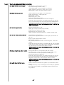
IMPORTANT NNOTES
The installation and Servicing of this fire MUST only be carried out by a competent person (such as a CORGI
registered fitter) in accordance with the Gas Safety (Installation and Use) Regulations 1998, the relevant British
Standards, Codes of Practice, the Building Regulations and the manufacturer's instructions.
Failure to comply with the above recommendations could lead to prosecution and invalidate the appliance war-
ranty.
Please ensure you are handed all of the manufacturers documents on completion of the installation. This will
include these instructions.
Always keep a note of the installer's name and address, the original purchase receipt and the date of installation
for future reference.
The fire should be serviced regularly to ensure continued safe operation. See the servicing section of the
Installation Instructions for further reference.
Parts of this appliance become naturally hot during use. It is recommended that a suitable fireguard conform-
ing to BS 8423 is used, especially where young children, pets, the elderly or infirm are concerned.
The manufacturer of this appliance considers all surfaces as working surfaces with the exception of the control
knob, control panel and ash pan cover.
This appliance is intended as a secondary source of heat only, and should not be used in a room without some
form of background heating present.
Combustible items, such as flooring and furniture and soft wall coverings (such as blown vinyl or embossed
paper), low temperature surrounds etc may discolour if fitted too close to the fire. See relevant section for fur-
ther details on clearances to combustibles. No combustible materials or flooring should protrude onto the
hearth.
This appliance incorporates a safety monitoring device (Oxygen Depletion Sensor).
DO NOT burn any foreign material on this fire. The coals must be of the correct type and laid out in accordance
with the relevant section of the these instructions. Failure to do so may create a hazard or lead to sooting.
Under no circumstances shall the appliance be used if the glass front door or panel has been removed, dam-
aged or is open.
The integral catalytic converter should be checked by the installer upon servicing to ensure there are no defects
or obstructions that may prevent the satisfactory flow of combustion products.
The expected life of the catalytic converter is in excess of 11,000 hours (10 years of normal use). After this time
the catalytic converter should be replaced.
WARNING: Due to the nature of this product the area around the top of the fire (i.e. the trim) gets very hot. Care
should be taken when operating the appliance.
1
1.0

FIREFRONT
This fire is supplied with a particular style of fire front. Use of the fire front will ensure an adequate airflow under
the firebox for the correct functioning of this appliance. Compliance with safety standards cannot be guaranteed
when another style of front is used.
CLEARANCES TTO CCOMBUSTIBLES
A non-combustible shelf may be fitted to within 100mm of the top edge of the fire frame. However the items
placed on it must also be able to withstand high temperatures.
A combustible shelf may be fixed to the wall above the fire, providing that is complies with the dimensions given
below.
Combustible materials, such as wood, may be fitted to within 100mm (4in) of either side of the frame of the
appliance, providing the forward projection does not exceed 100mm (4in).
Any combustible sidewalls must be at least 500mm to the side of the radiant heat source.
As with all heating appliances any decorations soft furnishings and wall coverings (i.e. flock, blown vinyl and
embossed paper) positioned too close to the appliance may discolour or scorch.
VENTILATION AAND RROOM SSIZE
Purpose provided ventilation of 100cm
2
is required for this appliance. An openable window or louvre is also
required.
Any ventilation fitted must comply with BS 5871 part 2 and BS 5440 part 2. Ventilation fitted under, or within
immediate vicinity of the appliance must not be used as it may adversely effect performance of the combustion
monitoring system (ODS) system.
The requirements of other appliances operating in the space or room must be taken into consideration when
assessing ventilation requirements, this will have been carried out by your CORGI registered installer.
A supply of fresh air into the room is advisable to maintain temperatures within limits.
The appliance MUST NOT be installed in a bedroom, bathroom or any sleeping area.
For Republic of Ireland, see relevant rules in force.
The room size should be a minimum of 30m
3
to allow adequate circulation of air and ensure the correct oper-
ation of the fire. This volume may include adjacent spaces, but these spaces must not be seperated by a door.
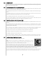
OPERATING IINSTRUCTIONS
The pilot is visible through the left hand side of the matrix.
Push in and turn the control knob to the SPARK position, and hold there for a few sec-
onds.
Continue turning anti-clockwise through the spark click to the PILOT light position, ensur-
ing the pilot has lit. If not, return the knob clockwise, and repeat.
When the pilot lights after the spark, keep the knob depressed for approximately ten sec-
onds. Now release the knob and the pilot should stay alight. If the pilot extinguishes dur-
ing use, wait three minutes before repeating the ignition procedure. To achieve the HIGH setting, push the con-
trol knob in slightly and continue turning anti-clockwise to the high position. The main burner should light after
a few seconds. To decrease the setting to LOW, turn the control knob clockwise to the low setting.
To turn to the PILOT position from the HIGH or LOW positions, press the control knob in, and return to the pilot
position and release. To turn the fire OFF, keep the knob pressed in, return to the off position and release.
2
2.0
3.0
4.0
5.0

COMBUSTION MMONITORING SSYSTEM
This fire is fitted with a combustion monitoring safety device (ODS). If the fire shuts down during use for no
apparent reason then several reasons may be suspected. If a door or window has been opened creating a
draught, then pilot disturbance could be the problem and removal of the draught should resolve this. The fire
can then be re-lit in accordance with the previous section. A grommet seal may also be missing from the fire-
box causing abnormal draught to shut down the pilot. Call your installer to check seals are properly fitted.
If pilot disturbance is not the cause, then the ODS safety system may be in operation. Switch the appliance OFF,
call in your installer to check the appliance and ventilation. Remedial work must be carried out as required. DO
NOT allow the appliance to be used until the appliance and installation is passed as safe. If the pilot continues
to be extinguished you must call your installer to check the operation of the complete appliance.
CLEANING
Before carrying out any of the following operations ensure that the fire is OFF and completely cold.
Debris that may form on the fire bed should be periodically removed by a competent person. Large deposits
could indicate incorrect coal placement. This should be remedied by a competent person and the fire serviced
before further use. To gain access to the fire bed, remove the hood and glass door assembly. The hood should
be lifted and pulled outwards. Next remove the door by removing the 2 screws and disengaging the 2 lugs at
the bottom. The glass can be cleaned using a proprietory hob cleaner. Test on a small area first.
FIREFRONT - Any dust accumulating in the fire front may be removed using a vacuum cleaner or dry cloth.
Heavy stains may be removed by using a damp cloth and mild household detergent. Brass parts of the fire front
may be cleaned using a suitable brass cleaner. Replace the front centrally against the fire after cleaning.
PAINTED AREAS - These can be cleaned using a dry cloth.
CERAMICS
Refer to the relevant section of the Installation section of this booklet for instructions on cleaning and replacing
the ceramics.
SERVICING
The fire should be checked on an annual basis to ensure it is working safely and that there is no excessive build
up of soot. The frequency of service will depend on usage but MUST be carried out at least once annually.
Servicing must be carried out by a competent person, such as a CORGI registered installer.
Cleaning of the coals may be carried out by following the instructions given in the Installation section. The
Installation instructions carry full servicing details for the use by the installer.
LIST OOF SSPARE PPARTS
PAART NNO. ITEM
FT/F780054 Ceramic combustion matrix
FB/F550085 Ceramic brick panel set
FB004225/5 Glass door assembly
FT004135/5 Convector Hood
FT/F730023 Pilot assembly
FT003835/5 Burner tray
Please enquire Gas valve
FB/F780052 Catalyst (seal kit must also be supplied)
FB/F940136 Seal kit for Catalyst
Please enquire Decorative frame
Please enquire Decorative fret
3
Maximum ddepth oof sshelf Minimum ddistancce ffrom hhearth tto uunderside oof sshelf
180mm 850mm
100mm 790mm
6.0
7.0
8.0
9.0
10.0
As our policy is one of continuous improvement and development , we hope therefore you will understand we must retain the right to amend details and/or specifications
without prior notice.
DO005515/0
-
 1
1
-
 2
2
-
 3
3
-
 4
4
-
 5
5
-
 6
6
-
 7
7
-
 8
8
-
 9
9
-
 10
10
-
 11
11
-
 12
12
-
 13
13
-
 14
14
-
 15
15
-
 16
16
-
 17
17
-
 18
18
-
 19
19
-
 20
20


Firecraft P30G FXL01 User manual
- Category
- Fireplaces
- Type
- User manual
- This manual is also suitable for
Ask a question and I''ll find the answer in the document
Finding information in a document is now easier with AI
Other documents
-
Focal Point Afina Flueless Inset User manual
-
-
-
-
-
-
-
-
-