tekmar Zone Control 368 Installation guide
- Category
- Thermostats
- Type
- Installation guide
This manual is also suitable for

- Data Brochure
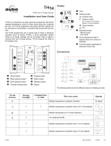
Zone Control 368
D 368
09/96
The Zone Control 368 is a microprocessor-based energy management control that uses PID
logic to control the temperature in up to 4 heating zones. Multiple zone controls can be
connected together for additional zones of heating. Either single stage or two stage zones can
be provided by the control. The 368 is primarily designed for use with the tekmar House
Controls. When connected to a House Control, the 368 provides indoor temperature feedback
that adjusts the supply water temperature in order to satisfy the zone with the highest heat
load. The 368 also coordinates the zoning operation in order to minimize boiler short cycling
and allow boiler purging between cycles. The 368 has a built in night setback timer and an
Optimum Start / Stop feature that allows the control to reheat the zones before the end of the
setback period.
Control Strategy . . . . . . . . . . . . . . . . pg. 2 Testing the Control . . .pg. 9
Sequence of Operation . . . . . . . . . . pg. 3 Error Messages . . . . . . pg. 11
Installation . . . . . . . . . . . . . . . . . . . . pg. 6 Technical Data . . . . . . . pg. 12
Settings . . . . . . . . . . . . . . . . . . . . . . . pg. 8 Limited Warranty . . . . . pg. 12
Zone Control 368
One & Two Stage
H1144 1
Made in Canada by
tekmar Control Systems Ltd.
N
3 4
Power
L
8 91011
Power
Pump Relay
Zone Relays
120 V 50/60 Hz 5 VA
120 V (ac) 6 A 1/3 hp, pilot duty 240 VA
120 V (ac) 6 A 1/3 hp, pilot duty 240 VA
Sep 96
31000266
2019
Do not apply power here
17 18
70°F
(21°C)
40
(4)
100
(38)
UnOccupied
5 6 7
LR 58223
NRTL/C
R
Occupied
Optimum Start / Stop
UnOccupied
Timer Active
24 hr. Timer
0
12 hrs.
24
618
• Dial the desired duration of the
UnOccupied period.
• Press start button at the time of day
you want the UnOcc. period to begin.
Timer Active light turns on.
Start
12 13 14
Com
Sen
RTU
1
RTU
2
Com
Sen
UnO
Sw
Zo
In
Com
Sen
1615
Caution: Signal wiring must be rated at least 300V
UnOccupied
Duration
0 = always Occupied
24 = always UnOccupied
M
M
M
M
PRGM
S
TIME
AMPM
UNOCC
OVR
SMWTFT
1
2
LR 58233
E150539
70
70
Power
Heat Required
Zone 2 / Hi stage
Zone 1 / Lo stage
2
3
4
1
Zone 4 / Hi stage
Zone 3 / Lo stage
Zo
Out
RTU
3
RTU
4
3-4
Com
341-2
Com
12
70
70
LR 58233
E150539
Test
Off
Optimum Start
Thermal Motor
Zone
Occ/UnOcc
1
32
Occ. only
4
System Pump
Pmp
1 2
System
Pmp
Input
120 V (ac)
Power
Supply
Input
tekmar Zone
Control
Input
tekmar RTUs
or Indoor
Sensors
Outputs
Zone Valves or
Zone Pumps
Input
tekmar
Timer
Output
tekmar Reset
Control
Output
System
Pump
Outputs
Zone Valves or
Zone Pumps
Zone Control 368
One & Two Stage
Power
Heat Required
Zone 2 Hi stage
System Pump
24 hr. Timer
• Dial the desired duration
of the UnOccupied period.
• Press start button at the time of day
you want the UnOcc. period to begin.
Timer Active light turns on.
Start
UnOccupied
Duration
0 = always Occupied
24 = always UnOccupied
Zone 1 Lo stage
2
3
4
1
Zone 4 Hi stage
Zone 3 Lo stage
70°F
(21°C)
40
(4)
100
(38)
UnOccupied
Occupied
Optimum Start / Stop
UnOccupied
Timer Active
0
12 hrs.
24
618
LR 58223
NRTL/C
R

2
Control Strategy
ZONING OPERATION
In a multiple zone heating system, the zones may have different internal heat gains, heat losses or different temperature settings. Each
zone must therefore have individual temperature control. For maximum comfort, the heat should be continuously supplied to the zone
at the same rate the zone is losing heat. The most accurate method of accomplishing this is by outdoor reset; however, it is not normally
economical to modulate the supply water temperature to every zone.
Outdoor reset can be combined with zoning for a more cost effective solution. Through
indoor sensors, a zone control can provide indoor temperature feedback to the outdoor
reset control. The outdoor reset control will then adjust the supply water temperature to
satisfy the zone with the highest water temperature requirement. Heat to the remaining
zones will be cycled on and off by the zone control using zone valves or pumps. Since the
heat is cycled on and off, accurate PID control logic should be provided to maintain a stable
indoor temperature.
PID Zoning Logic
Proportional (P)
In order to prevent indoor temperature swings, the heat supplied to each zone must be
proportional to the heat required by the zone. Proportional control logic can be
accomplished by pulse width modulation (PWM). A typical PWM system has a fixed
operating cycle. During this operating cycle, the on time of the zone relay is varied
based on the difference between the desired zone temperature and the actual zone
temperature. As the zone temperature drops, the relay on time increases and as the
zone temperature rises, the relay on time decreases.
Integral (I)
Controls that are strictly proportional suffer from a problem of offset. The amount of heat
supplied to the zone depends on how far the space temperature is below the desired
setpoint. This implies that as the heating load increases, the average room temperature
droops. On the coldest day of the year, the most heat is required and therefore the room
temperature must be coldest.
In order to overcome this offset, integral control logic is used. Only digital controls can provide integral control logic due to the lengthy
response time of buildings. Integral control logic is based on time. The longer the room temperature is below the desired setpoint,
the more heat is supplied to the room. With integral control logic, full heat can be supplied to the room on the coldest day of the
year without requiring that the room be cold.
Derivative (D)
In order to speed up the control’s response to quick changes in the heating load, derivative control logic is required. However,
sudden room temperature changes, for example from an open door or window, should be ignored by an intelligent control.
P + I + D = PID
If proportional, integral and derivative (PID) control logic are combined, the control is more able to prevent excessive temperature
swings and provide a stable room temperature under all conditions. It not only takes into account how much the room temperature
has drooped, but also how long there has been a droop and how fast the temperature is changing.
Zone Load Staggering
In a multiple zone system, there can be sudden load changes on the boiler and system
due to multiple zones turning on or off. These sudden load changes often lead to boiler
short cycling and unnecessary mechanical stresses. The operation of the system can be
improved by staggering the starting points of each zone relay within the operating cycle.
Staggering of the zones maintains a relatively constant system flow rate which improves
boiler operation. Controlled staggering can also minimize boiler running time and improve
system efficiency when only a few zones are needed for short periods.
Zone Post Purge
Before the last zone is turned off in a heating cycle, the boiler is turned off but the zone continues to draw heat from the boiler. This
post purge of the boiler reduces stand-by losses and reduces overall energy consumption.
UNOCCUPIED (NIGHT SETBACK)
During the night, or at times when people are not within the building, energy can be saved by lowering the building temperature for an
UnOccupied (Night Setback) period.
Due to the large thermal mass of buildings, it takes a long time for the indoor space temperature to significantly change whenever the
heating system is turned on or off. The building heat up or cool down time is further increased when high mass heating systems are
used (e.g. radiant floors). In most cases night setback cannot be used with these systems due to the long recovery time required in the
morning. A typical system is demonstrated in the diagram on page 3.
Zone 1
Zone 2
Zone 3
Zone 4
Post Purge
(Boiler off, Pump on)
On
On
On
On
On
70 °F
(21°C)
15 minutes
15 minutes
13 minutes
no heat
72 °F
(22°C)
68 °F
(20°C)
droop
70 °F
(22°C)
15 minutes
15 minutes
5 minutes
10 minutes
on
no heat
72 °F
(22°C)
68 °F
(20°C)
Heat
Source
90%
time on
85%
time on
100%
time on
M
M
M

3
At the start of the night setback period the heat is turned off, but the heat
contained within the slab or radiator continues to heat the building and
there is a delay before the space temperature begins to drop. At the end
of this delay the temperature within the building gradually decreases, and
may eventually reach the required UnOccupied temperature after suffi-
cient time has elapsed. Once the setback period is complete, the heat is
turned on again but there is a long recovery time required to raise the
space temperature to the desired setpoint. The length of the delay and
recovery periods changes with outdoor temperature and is different for
each zone within the building.
A comfortable setback can be provided if the control “learns” the
response time for each zone within the building. Based on the zone’s
response time, the control can then calculate an Optimum Stop time and
an Optimum Start time. At the Optimum Stop time the control turns off the
zone valve or pump in order to overcome the delay period and at the
Optimum Start time, the control starts to raise the zone temperature in
order to overcome the recovery period. This allows night setback to be
used with most heating systems.
Optimum Start / Stop with Water Temperature Boost
When Optimum Start / Stop is combined with Outdoor Reset, the
control can boost the water temperature during the recovery period.
This provides a faster recovery and allows a longer setback for greater
energy savings.
The accuracy of the Optimum Start / Stop routine depends on the
feedback available to the control.
Optimum Start / Stop with both Outdoor and Indoor Sensors
The response time of the building varies with outdoor temperature and is also different
for each zone. The most accurate Optimum Start / Stop routine is therefore achieved
when both the indoor and outdoor temperatures are monitored during transitions between
UnOccupied and Occupied modes.
Optimum Start / Stop with only Indoor Sensors
When only indoor temperature feedback is available, the control must base all Optimum
Start / Stop calculations on
indoor temperature only. If there are large variations in outdoor
temperature, this method cannot provide the same level of accuracy as when both indoor
and outdoor sensors are used.
Optimum Start / Stop with only an Outdoor Sensor
Every building, and often each zone within the building, has a different response time.
When only an outdoor sensor is used, the control must assume a particular response time
for the entire building. Therefore this is generally the least accurate method of calculating
Optimum Start / Stop times.
Sequence of Operation
POWERING UP THE CONTROL
After the Zone Control 368 is powered up, a software version code is displayed for 2 seconds
and the red indicator lights are then turned on for 4 seconds. Once the control is powered
up, the green
Power
light remains on continuously. For the first fifteen minutes after power
up, the
Test
light flashes and the control responds immediately to setting changes. This
allows the installer to test the operation of the system. After fifteen minutes, the control
enters its normal operating mode in which reactions to setting changes are significantly
slower. A slower reaction time allows the control to provide a more stable room temperature.
ZONING OPERATION
The 368 can directly control the temperature of up to 4 One Stage heating zones or 2 Two
Stage heating zones or a combination of One Stage and Two Stage zones. In order to
measure the indoor temperature, each zone requires either an Indoor Sensor or a Room
Temperature Unit (RTU). With an RTU the desired zone temperature is set using the RTU
dial, but with an Indoor Sensor the desired zone temperature is fixed at 72°F (22°C).
Outdoor
Sensor
Room
Temperature
Units (RTU's)
Room
Temperature
Units (RTU's)
Outdoor
Sensor
Delay
Period
6 A.M.9 P.M.
10 P.M. 8 A.M.
Room Temperature
Setback Period
Optimum
Stop
Shorter
Recovery
Period
Optimum
Start
UnOcc
65°F (18°C)
Occ
70°F
(21°C)
Delay
Period
8 A.M.10 P.M. 11 P.M. 11 A.M.
Recovery
Period
Setback Period
Occ
70°F (21°C)
UnOcc
65°F
(18°C)
Delay
Period
5 A.M.9 P.M.
10 P.M. 8 A.M.
Room Temperature
Setback Period
Optimum
Stop
Recovery
Period
Optimum
Start
Occ
70°F
(21°C)
UnOcc
65°F (18°C)
70
Indoor SensorRTU
Only in the first 15 minutes after power up, does the
control respond immediately to settings adjustments.
70
M

4
Common Blocks
The 368 has 2 common blocks for both the RTU inputs and the relay outputs. Each
common block has a terminal starting with
Com
(Eg.
Com Sen
or
Com 1-2
). Each
common block can be used for either two One Stage zones or one Two Stage zone.
One Stage Common Blocks
If an RTU is connected to the lowest number in the common block, a One Stage common
block is created.
Example An RTU connected between the terminals
Com Sen
—
RTU 1
is used to control
the output relay
1,
and an RTU connected between the terminals
Com Sen
—
RTU 2
is used to control the output relay
2
.
Note If only one RTU is used, it must be placed on the lower number in the common
block. In the above example this would be
Com Sen
—
RTU 1
controlling output
relay
Com 1-2
—
1.
PID Zoning Logic
The 368 operation is based on a 15 minute cycle. During each cycle,
the control turns on the zone relay for a specific on time. This zone
on time is calculated based on the PID response of the zone during
the previous 15 minute period. If the zone needs more heat, the on
time is increased and if the zone needs less heat, the on time is
reduced. In order to prevent short cycling, the 368 ensures that the
zone relays remain on or off for at least 3 minutes.
Two Stage Common Blocks
When a single RTU is connected to the highest terminal number in the common block,
a Two Stage common block is created. The single RTU therefore controls two output
relays: a
Lo stage
relay and a
Hi stage
relay.
Example An RTU connected between the terminals
Com Sen
—
RTU
2
is used to
control the output relays
1
and
2
. Relay
1
is the
Lo stage
output relay and relay
2
is the
Hi stage
output relay.
PID Zoning logic
The temperature within each Two Stage zone is controlled by
varying the on time of the output relays over a 15 minute period.
During light loads, the 368 cycles the
Lo stage
relay on and off. As
the load increases, the
Lo stage
relay on time increases until it
reaches a maximum of 15 minutes. The
Hi stage
relay is then turned
on and its on time is increased as the load increases. When the
heating load decreases again, the on time of the
Hi stage
relay is
reduced until the
Hi stage
relay is turned off completely. The control
then starts to reduce the on time of the
Lo stage
relay.
Zone Control Load Staggering and Synchronization
The 368 staggers the operation of the zones in order to achieve a steady load on the boiler while minimizing boiler running time and
preventing boiler short cycling. Multiple Zone Controls can be connected together to increase the number of zones. Each of the Zone
Controls synchronizes its zone operating cycles based on the
Zo In
input from the other Zone Controls. This results in a more stable
system flow rate and improved boiler operation.
Zone Control Operation with a tekmar House Control
The 368 can communicate with a tekmar House Control in order to
provide indoor temperature feedback, turn on the system pump and
operate the boiler. When multiple Zone Controls are used, each Zone
Control sequentially passes the information to the tekmar House
Control. This ensures that the heat requirements of all zones are
satisfied. When the 368 is requesting heat from the House Control, the
Heat Required
light is turned on.
Fast Acting Zone Valves or Zone Pumps
If the
Thermal Motor
DIP switch is set to
Off
, the 368 assumes that fast acting (electric
motor) zone valves or zone pumps are connected to the zone relays. The
Heat Required
light is therefore turned on as soon as the first zone relay is turned on. One minute before
the last zone relay is turned off, the 368 purges the boiler by signaling to the House Control
to turn off the boiler and keep the system pump operating.
LR 58233
E150539
LR 58233
E150539
tekmar Zone Control
tekmar Zone Control
15 minute Cycle
Lo Stage
Lo Stage
Hi Stage
Hi Stage
Lo Stage
Hi Stage
Lo Stage
Off
Off
Off
On
On
On
On
On
H
C
R
Lo
Stage
Hi
Stage
MM
Com
1-2
15
1
16
2
17
Com
Sen
56
RTU
1
RTU
2
7
Relay On Time
Relay On Time
Relay On Time
Less Heat
More Heat
15 minute Cycle
H
C
R
Zone 1
Zone 2
H
M M
Com
1-2
15
1
16
2
17
Com
Sen
56
RTU
1
RTU
2
7
Fast acting
zone valve
or zone pump
Off
Thermal Motor

5
Slow Acting Zone Valves with Thermal Motors
When the DIP switch is set to
Thermal Motor
, the 368 assumes that slow acting zone
valves with thermal actuating motors are connected to the zone relays. With slow acting
zone valves, the 368 allows a 3 minute period for the first zone valve to open before the
Heat Required
light is turned on. The total operating time for the zone relays is also
increased by an extra 2 minutes. This helps compensate for the longer opening versus
closing time of the slow acting zone valves. Once the last zone relay is turned off, the 368
purges the boiler for one minute by signaling to the House Control to turn off the boiler
and keep the system pump operating.
UNOCCUPIED (NIGHT SETBACK)
The 368 can be switched into UnOccupied mode through the built in 24 hr. Timer or by
closing an external switch or timer relay wired between the terminals
UnO Sw — Com Sen
(11 & 13) on the control.
24 hr. Timer
The 368 has a built in 24 hr. Timer which can be used to set a single UnOccupied event
during a 24 hour period. The 24 hr. Timer is activated by pushing the
Start
button at the
desired starting time for the UnOccupied period. The duration of the UnOccupied period
is then set using the
UnOccupied Duration
dial. Once the
Start
button is pushed, the
Timer
Active
light is turned on and the 368 enters the UnOccupied mode each day at the same
starting time. The 24 hr. Timer can be deactivated by pressing the
Start
button again. A
new UnOccupied period starting time can be selected by repeating the above procedure.
Note If an external switch is closed between the terminals
UnO Sw — Com Sen
(11 & 13), the 24 hr. Timer is disabled. An external UnOccupied switch and the 24
hr. Timer should not be used at the same time.
UnOccupied Switch Input
A switch or external timer with a dry relay contact output can be wired between the
terminals
UnO Sw — Com Sen
(11 & 13) on the 368. When the switch or relay contact
is closed, the 368 registers an UnOccupied signal. A tekmar Timer 031 is available which
can be programmed to provide individual UnOccupied schedules for each day of the week
with up to two separate UnOccupied events per day. For more information on the Timer
031 see the Data Brochure D 031.
UnOccupied Temperature
When the 368 is in UnOccupied mode, the
UnOccupied
light is turned on and the
UnOccupied
dial is used to set the desired temperature within the UnOccupied zones.
Note If the RTU dial for an UnOccupied zone is set below the
UnOccupied
dial, the 368
continues to use the RTU dial as the desired temperature within that zone.
Individual Zone Selection
The DIP switch on the 368 is used to select which zones are switched into UnOccupied
mode. If the DIP switch for a specific zone is set to
Occ / UnOcc
, the zone is switched into
UnOccupied mode whenever the 368 receives an UnOccupied signal. If the DIP switch
for a specific zone is set to
Occ. only
, the zone remains in the Occupied mode at all times.
Optimum Start / Stop
The Optimum Start / Stop feature is enabled when the DIP switch is set to
Optimum
Start.
The 368 turns on the
Optimum Start / Stop
light each time the first zone enters its
delay or recovery period. Either the tekmar Timer 031 or the built in 24 hr. Timer on the 368
can be used with the Optimum Start / Stop feature. The tekmar Timer 031 has a DIP switch
which must be set to
Optimum Start / Stop
in order to synchronize the timer with the 368
Optimum Start / Stop function. For more information on the Timer 031 consult the Data
Brochure D 031.
SYSTEM PUMP OPERATION
The
System Pump
light is turned on every time the relay contact between terminals
System Pmp — System Pmp
(1 & 2) is closed. During
heating operation, the system pump operates whenever any zone requires heat. If thermal motor zone valves are used, the system pump
is held off for the first three minutes of the zone cycle in order to give the zone valve sufficient time to open. The system pump may also
operate for an additional purge period once the zone relays are turned off.
Pump / Valve Exercising
The zone valves, zone pumps and system pump are exercised to help prevent corrosion from building up and subsequently jamming
the equipment. Every three days the 368 runs through the following exercising procedure.
UnOccupied
70°F
(21°C)
40
(4)
100
(38)
UnOccupied
Off
Optimum Start
Occ/UnOcc
Occ. only
Zone 11234
SCHD
Su
TIME
AMPM
UNOCC
OVR
SaMo WeTh FrTu
1
2
Zo
Out
1211
UnO
Sw
Com
Sen
13
Occupied
Optimum Start / Stop
UnOccupied
Timer Active
24 hr. Timer
0
12 hrs.
24
618
• Dial the desired duration of the
UnOccupied period.
• Press start button at the time of day
you want the UnOcc. period to begin.
Timer Active light turns on.
Start
UnOccupied
Duration
0 = always Occupied
24 = always UnOccupied
Slow acting
zone valve
Off
Thermal Motor

6
Exercising Procedure
The 368 first exercises the zone valves or pumps. If a zone valve or zone pump has not been operated in the past 3 days, the 368
turns on the zone relay for 10 seconds.
Note The zone relay exercising time is increased to 3 minutes if the DIP switch is set to
Thermal Motor
.
After the zone valves or pumps have been exercised, the 368 exercises the system pump. If the system pump has not operated
in the past 3 days, the 368 turns on the
System Pmp
relay for 10 seconds.
Once the exercising procedure is complete, the 368 returns to its normal operating sequence.
Installation
Caution Improper installation and operation of this control could result in damage to the equipment and possibly even
personal injury. It is your responsibility to ensure that this control is safely installed according to all applicable codes
and standards. This electronic control is not intended for use as a primary limit control. Other controls that are
intended and certified as safety limits must be placed into the control circuit.
STEP ONE
GETTING READY
Check the contents of this package. If any of the contents listed are missing or damaged, please contact your wholesaler or tekmar sales
representative for assistance.
Type 368 includes:
• One Zone Control 368
• Data Brochures D 368, D 001
• Application Brochures A 368
Other information available:
• Essays
Note
Carefully read the details of the Sequence of Operation sections in all applicable brochures to ensure that you have chosen the
proper control for your application.
STEP TWO
MOUNTING THE BASE
Remove the control from its base by pressing down on the release clip in the wiring chamber and sliding the control upwards. The base
is then mounted in accordance with the instructions in the Data Brochure D 001.
STEP THREE
ROUGH-IN WIRING
All electrical wiring terminates in the control base wiring chamber. The base has standard 7/8" (22 mm) knockouts which accept common
wiring hardware and conduit fittings. Before removing the knockouts, check the wiring diagram and select those sections of the chamber
with common voltages. Do not allow the wiring to cross between sections as the wires will interfere with safety dividers which should
be installed at a later time.
Power must not be applied to any of the wires during the rough-in wiring stage.
• If a 10K Indoor Sensor is used for any zone, install the Indoor Sensor(s) according to the instructions in the Data Brochure 074 and
run the wiring back to the control.
• If a 10K RTU is used, install the RTU(s) according to the installation instructions provided in the Data Brochure D 054 and run the
wiring back to the control.
• If multiple Zone Controls are used, run two wires from one Zone Control to the next to create a chain.
• Run wires from the 120 V (ac) power to the control.
Use a clean power source to ensure proper operation.
Multi-strand 16 AWG
wire is recommended for all 120 V (ac) wiring due to its superior flexibility and ease of installation into the terminals.
• Run wires from the system pump and from each zone valve / pump to the control.
STEP FOUR
ELECTRICAL CONNECTIONS TO THE CONTROL
The installer should test to confirm that no voltage is present at any of the wires. Push the control into the base and slide it down until
it snaps in firmly.
Powered Input Connections
120 V (ac) Power
Connect the 120 V (ac) power supply to terminals
Power N — L
(3 and 4).
Sensor and Unpowered Input Connections
Do not apply power to these terminals as this will damage the control.
Zone Control Input and Output
Connect a wire between the
Com Sen
(13) terminals on each 368. Connect the
Zo Out
(12) terminal on the first 368 to the
Zo In
(14) terminal on the second 368. With several
Zone Controls, connect the
Zo Out
(12) terminal on the second 368 to the
Zo In
(14)
terminal on the third 368 and continue this process for each additional 368. The
Zo Out
Com
Sen
UnO
Sw
56
RTU
1
1211 1 3
Com
Sen
14
Zo
In
Zo
Out
RTU
2
7
RTU
3
9
RTU
4
108
Com
Sen
Com
Sen
UnO
Sw
56
RTU
1
1211 13
Com
Sen
14
Zo
In
Zo
Out
RTU
2
7
RTU
3
9
RTU
4
108
Com
Sen
3
12
N
L
Pmp
4
Power
Pmp
System

7
(12) terminal on the last 368 in the chain can be connected to the
Zo In
terminal on a
tekmar reset control.
Note The wires from the Zone Control are polarity sensitive. The system will not
operate if the wires are reversed.
UnOccupied Switch
If an external timer or switch is used, connect the two wires from the external dry
contact switch to the
UnO Sw — Com Sen
(11 and 13) terminals. When these
terminals short together, the control registers an UnOccupied signal.
Note If an external switch is closed between the terminals
UnO Sw — Com Sen
(11 and 13), the 24 hr. Timer is disabled and the Optimum Start / Stop
information is lost. It is recommended that either the 24 hr. Timer or an
external timer / switch is used, not both at the same time.
One Stage RTU and Indoor Sensor Connections
RTUs and Indoor Sensors provide indoor temperature feedback to the control.
Common block for
RTU 1
and
RTU 2
• If the common block is used for a single One Stage heating zone, connect the RTU
or Indoor Sensor to terminals
Com Sen
—
RTU 1
(5 and 6).
• If the common block is used for 2 One Stage heating zones, connect one RTU or
Indoor Sensor to the
Com Sen
—
RTU 1
(5 and 6) terminals and connect the other
RTU or Indoor Sensor to the
Com Sen
—
RTU 2
(5 and 7) terminals.
Common block for
RTU 3
and
RTU 4
• If the common block is used for a single One Stage heating zone, connect the RTU
or Indoor Sensor to terminals
Com Sen
—
RTU 3
(8 and 9).
• If the common block is used for 2 One Stage heating zones, connect one RTU to
the
Com Sen
—
RTU 3
(8 and 9) terminals and connect the other RTU to the
Com
Sen
—
RTU 4
(8 and 10) terminals.
Two Stage RTU and Indoor Sensor Connections
Common Block for
RTU 1
and
RTU 2
• If the common block is used for a Two Stage heating zone, connect the RTU or
Indoor Sensor to terminals
Com Sen
—
RTU 2
(5 and 7).
Common Block for
RTU 3
and
RTU 4
• If the common block is used for a Two Stage heating zone, connect the RTU or
Indoor Sensor to terminals
Com Sen
—
RTU 4
(8 and 10).
Output Connections
System Pump
Connect the live (L) side of the 120 V (ac) pump circuit through the
System Pmp
—
System Pmp
(1 and 2) terminals. The control closes a dry relay contact between these
terminals when operation of the system pump is required.
Zone Pumps and Valves
Note Do not connect a zone pump and zone valve circuit to the same
Com
terminal.
• If relay
1
is used, connect the zone pump or zone valve circuit to the
Com 1-2 — 1
(15 and 16) terminals on the control.
• If relay
2
is used, connect the zone pump or zone valve circuit to the
Com 1-2 — 2
(15 and 17) terminals on the control.
• If relay
3 is
used, connect the zone pump or zone valve circuit to the
Com 3-4 — 3
(18 and 19) terminals on the control.
• If relay
4
is used, connect the zone pump or zone valve circuit to the
Com 3-4 — 4
(18 and 20) terminals on the control.
STEP FIVE
TESTING THE WIRING
Each terminal block must be unplugged from its header on the control before power
is applied for testing. Pull straight down to unplug the terminal block.
Com
Sen
UnO
Sw
56
RTU
1
1211 13
Com
Sen
14
Zo
In
Zo
Out
RTU
2
7
RTU
3
9
RTU
4
108
Com
Sen
15 16 17
1
18 19
3
4
20
Com
1-2
2
Com
3-4
15 16 17
1
18 19
3
4
20
Com
1-2
2
Com
3-4
15 16 17
1
18 19
3
4
20
Com
1-2
2
Com
3-4
15 16 17
1
18 19
3
4
20
Com
1-2
2
Com
3-4
3
12
N
L
Pmp
4
Power
Pmp
System
Com
Sen
UnO
Sw
56
RTU
1
1211 13
Com
Sen
14
Zo
In
Zo
Out
RTU
2
7
RTU
3
9
RTU
4
108
Com
Sen
Com
Sen
UnO
Sw
5 6
RTU
1
1211 13
Com
Sen
14
Zo
In
Zo
Out
RTU
2
7
RTU
3
9
RTU
4
108
Com
Sen
Com
Sen
UnO
Sw
56
RTU
1
1211 13
Com
Sen
14
Zo
In
Zo
Out
RTU
2
7
RTU
3
9
RTU
4
108
Com
Sen
Com
Sen
UnO
Sw
56
RTU
1
1211 13
Com
Sen
14
Zo
In
Zo
Out
RTU
2
7
RTU
3
9
RTU
4
108
Com
Sen
Com
Sen
UnO
Sw
56
RTU
1
1211 13
Com
Sen
14
Zo
In
Zo
Out
RTU
2
7
RTU
3
9
RTU
4
108
Com
Sen
Com
Sen
UnO
Sw
5 6
RTU
1
1211 13
Com
Sen
14
Zo
In
Zo
Out
RTU
2
7
RTU
3
9
RTU
4
108
Com
Sen

8
The following tests are to be performed using standard testing practices and procedures
and should only be carried out by properly trained and experienced persons.
A good quality electrical test meter, capable of reading from at least 0 — 200 V (ac) and at
least 0 — 2,000,000 Ohms, is essential to properly test the wiring and sensors.
Test the Sensors
In order to test the sensors and Room Temperature Units (RTUs), the actual temperature
at each sensor and RTU location must be measured. A good quality digital thermometer
with a surface temperature probe is recommended for ease of use and accuracy of
testing. Where a digital thermometer is not available, a spare sensor can be strapped
alongside the one to be tested and the readings compared. Test the sensors and RTU(s)
according to the instructions in the Data Brochures D 070, D 074 and D 054.
Test the Power Supply
Make sure exposed wires or bare terminals are not in contact with other wires or grounded surfaces. Turn on the power and measure
the voltage between the
Power N — L
(3 and 4) terminals using an AC voltmeter. The reading should be between 110 and 130 V (ac).
Test the Outputs
System Pump
If a system pump is connected to the
System Pmp — System Pmp
(1 and 2) terminals, make sure power to the terminal block is
off and install a jumper between the terminals. When the system pump circuit is powered up, the system pump should start. If the
pump does not turn on, check the wiring between the terminal block and the pump and refer to any installation or troubleshooting
information supplied with the pump. If the pump operates properly, disconnect the power and remove the jumper.
Zone Pump or Valve
• If a zone pump or valve is connected to the terminals
Com 1-2 —1
(15 and 16), make sure power to the pump or valve circuit is
off and install a jumper between the terminals
Com 1-2 —1
(15 and 16). When the zone circuit is powered up, the zone pump
should turn on or the zone valve should open completely. If this does not occur, check the wiring between the terminal and the
pump or valve and refer to any installation or troubleshooting information supplied by the manufacturer.
• If a zone pump or valve is connected to the terminals
Com 1-2 — 2
(15 and 17), follow a similar procedure as described above
for the zone 1 relay.
• If a zone pump or valve is connected to the terminals
Com 3-4 — 3
(18 and 19), follow a similar procedure as described above
for the zone 1 relay.
• If a zone pump or valve is connected to the terminals
Com 3-4 — 4
(18 and 20), follow a similar procedure as described above
for the zone 1 relay.
Connect the Control
• Make sure all power to the devices and terminal blocks is turned off and remove any remaining jumpers from the terminals.
• Reconnect the terminal blocks to the control by carefully aligning them with their respective headers on the control and then pushing
the terminal blocks into the headers. The terminal blocks should snap firmly into place.
• Install the supplied safety dividers between the unpowered sensor inputs and the powered 120 V (ac) or 24V (ac) wiring chambers.
• Do not apply power to the control until the adjustment dials and DIP switches are properly set for your application. See the Settings
section of this brochure for details on how to set the dials and DIP switches.
• Once the settings are complete, apply power to the control. The operation of the control on power up is described in the Sequence
of Operation section of this brochure.
Settings
Before adjusting the dial settings, read through the sequence of operation section of this brochure to ensure that you understand how
the control operates.
STEP SIX
ESSENTIAL CONTROL SETTINGS
UnOccupied
The
UnOccupied
dial is used to set the desired temperature in selected zones during the
UnOccupied period.
Using the Internal 24 hr. Timer
First determine the length of time required for the UnOccupied period and turn the
UnOccupied Duration
dial to the desired duration length. If the dial is set to 24 hours, the
368 remains in UnOccupied mode continuously. If the dial is set to 0 hours, the 368
remains in Occupied mode continuously.
8
9
10
12
11
13
14
Zo
Out
RTU
4
Zo
In
Com
Sen
RTU
3
UnO
Sw
Com
Sen
Ω
Ω
UnOccupied
Duration
Timer Active
24 hr. Timer
• Dial the desired duration of the
UnOccupied period.
• Press start button at the time of day
you want the UnOcc. period to begin.
Timer Active light turns on.
Start
0 = always Occupied
24 = always UnOccupied
0
12 hrs.
24
618
UnOccupied
Duration

9
Press the
Start
button at the desired starting time for the UnOccupied period. Once the
Start
button is pressed, the 368 enters the
UnOccupied period at the same starting time each day.
Example The user wants an UnOccupied period starting at 10 pm and ending at 6 am. The
Unoccupied Duration
dial is set to 8 hours
and the
Start
button is pushed at 10 pm. Once the
Start
button is pushed, the control goes into UnOccupied mode from
10 pm until 6 am the next morning. This cycle is repeated 7 days a week.
DIP Switch Settings
Occ / UnOcc — Occ. Only
Each zone can be selected to operate in either Occupied only mode or both Occupied
and UnOccupied modes. If the DIP switch is set to
Zone 1 Occ. only
, the zone
connected to relay
1
remains in Occupied mode at all times. If the DIP switch is set to
Zone 1 Occ / UnOcc
, zone
1
is switched into UnOccupied mode each time the 368
receives an UnOccupied signal. Zones
2, 3,
and
4
are set in a similar manner to that
described above for zone 1. If Two Stage zones are used, the DIP switches for both
output relays should be set to the same postion.
Optimum Start
The Optimum Start / Stop feature is used during transitions between the UnOccupied
mode (Night Setback) and the Occupied mode. When the DIP switch is set to
Optimum
Start
, the 368 raises the building temperature during the final stages of the UnOccupied
period. This helps ensure the building is at the Occupied temperature as soon as the
Occupied period begins. If the
Optimum Start
DIP switch is set to
Off
, the 368 does not
start raising the building temperature until the UnOccupied period ends. More informa-
tion on the Optimum Start feature is provided on page 3 of this brochure.
Thermal Motor
Zone valves with thermal actuating motors have long opening and closing times. In
order for the 368 to compensate for these longer times, the DIP switch should be set
to
Thermal Motor
. If fast acting electric motor zone valves or zone pumps are used, the
DIP switch must be set to
Off
.
Testing the Control Functions
STEP SEVEN
OPERATIONAL TEST OF CONTROL FUNCTIONS
The Zone Control 368 has a test routine which is used to test the main control functions. The 368 continually checks the sensors and
displays an error message whenever a fault is found. See page 11 for the list of error messages. When the
Test
button is pushed, the
Test
light is turned on. The
Heat Required,
and
Optimum Start / Stop
lights are turned off and the individual outputs and relays are tested
in the following test sequence.
Test Sequence
Each step in the test sequence lasts 10 seconds. At the end of each step, the device
continues to operate until it is turned off in a later step.
During the test routine, the test sequence can be paused by pressing the
Test
button. The
test sequence remains paused at that point for up to 5 minutes. If the
Test
button is not
pressed again while the test sequence is paused, the control exits the entire test routine.
Once the test sequence is paused, the
Test
button can be pressed again to skip to the
next step. This can also be used to rapidly skip through the test sequence. To reach the
desired step, repeatedly press and release the
Test
button until the appropriate device
and indicator light turn on.
Step 1 -
The
System Pump
relay is turned on.
Step 2 -
If the
Com 3-4
common block is used for a single One Stage zone, the control
turns on relay
3
for 10 seconds.
- If the
Com 3-4
common block is used for two One Stage zones, the control turns
on relay
4
for 10 seconds and then turns off relay
4
and turns on relay
3
for
10 seconds.
- If the
Com 3-4
common block is used for a Two Stage zone, the control turns
on relay
3
and then, after 10 seconds, turns on relay
4
as well.
- If an RTU is not connected to
RTU 3
or
RTU 4
, the control skips this step.
Step 3 -
The control tests relays
1
and
2
using the procedure described in Step 2.
Occ/UnOcc
Occ. only
Zone 11234
Off
Thermal Motor
Off
Optimum Start
Test
1
System Pump
System Pump
Zone 2 / Hi stage
Zone 3 / Lo stage
Zone 4 / Hi stage
Zone 1 / Lo stage
1
2
4
3
2
1

10
Step 4 -
After the test sequence is complete, the
Test
light begins flashing and the control enters a fast mode of operation. During
this time, the control is more responsive to setting adjustments. If the dial on an RTU is turned up, the on time of the zone
relay increases immediately. After fifteen minutes, the control reverts back to normal operating conditions and the on times
are based on the average temperature during the previous 15 minute cycle.
Manual Test
While the control is in the fast mode of operation and the
Test
light is flashing, check that
each RTU operates the proper zone valve or zone pump. Turn up the
RTU
dial to turn the
zone on, turn the dial down to turn the zone off. If an Indoor Sensor is used, a cold spray
to the sensor will turn the zone on.
Indicator Lights “On”
Power
• 120 V (ac) power is applied to the control and the control
is energized.
Heat Required
• The 368 is sending a heat required signal to a tekmar reset control. At least one of the heating zones
requires heat.
System Pump
• The relay contact between
System Pmp—System Pmp
(1 and 2) is closed and the System Pump should
be turned on.
Zone 1 / Lo Stage
• The relay contact between
Com 1-2— 1
(15 and 16) is closed and the device connected to this relay
should be turned on.
Zone 2 / Hi Stage
• The relay contact between
Com 1-2— 2
(15 and 17) is closed and the device connected to this relay
should be turned on.
Zone 3 / Lo Stage
• The relay contact between
Com 3-4— 3
(18 and 19) is closed and the device connected to this relay
should be turned on.
Zone 4 / Hi Stage
• The relay contact between
Com 3-4— 4
(18 and 20) is closed and the device connected to this relay
should be turned on.
Test
• The control is proceeding through the programmed test sequence.
Occupied
• The control is in Occupied mode.
UnOccupied
• The control is in UnOccupied (Night Setback) mode.
Optimum Start / Stop
• The control is warming the building up during the final stages of the UnOccupied period, or the heating
system is turned off during the final stages of the Occupied period.
Timer Active
• The timer is set to enter the UnOccupied mode every 24 hours at the time of day the
Start
button was
pressed.
STEP EIGHT
TROUBLESHOOTING
As in any troubleshooting procedure, it is important to isolate a problem as much as possible before proceeding. The Error Messages
and
Test
button greatly simplify troubleshooting of the 368. When the control is flashing an error message, identify the fault from the
look-up table on page 11 and follow standard testing procedures to confirm the problem. If you suspect a wiring fault, return to steps
three, four and five, and carefully check all external wiring and wiring connections.
Sensor and Internal Faults
• If an RTU / Indoor Sensor fault occurs or an external Zone Control input
Zo - in
short circuits, the 368 operates as if that RTU or
Zone Control is not connected. An error message is displayed.
• If an internal control fault occurs, the 368 displays an error message. Press the
Test
button to clear the error message. If the error
message remains, the control must be returned for repair.
STEP NINE
BEFORE YOU LEAVE
• Make sure the wiring safety dividers are installed in their proper locations between compartments with different voltages.
• Install the wiring cover over the wiring chamber and secure it to the base with the two screws provided. Place the front cover on the
control and snap it into place. Install a lock if security is required.
• A sticker has been provided with the control. It is designed to be placed over the Zone 1 ... Zone 4 words
so that the zone names can be written onto the control.
• Place this brochure, and all other brochures relating to the installation, in the protective plastic bag supplied
with the control.
• Place the bag in a conspicuous location near the control for future reference.
• It is important to explain the operation of the control to the end user and to anyone else who may be operating
the system.
Zone 3
Zone 2
Zone 4
Zone 1 /
Cooling
1
2
3
4
B
e
d
r
m
L
i
v
in
g
R
m
K
it
c
h
e
n
B
a
s
e
m
Adjusting RTU settings provides an immediate
response for the first 15 minutes only.
70
M
Test

11
Error Messages
Whenever a fault is detected in any of the sensors and / or room temperature units (RTUs), the indicator lights will flash in specific ways,
to indicate the location of the problem. For detailed Sensor and RTU testing instructions see Data Brochures D 070, D 074 and D 054.
RTU 1 short circuit RTU 2 short circuit RTU 3 short circuit RTU 4 short circuit
Power
Heat Required
Occupied
Optimum Start / Stop
UnOccupied
Timer Active
Power
Heat Required
Occupied
Optimum Start / Stop
UnOccupied
Timer Active
Power
Heat Required
Occupied
Optimum Start / Stop
UnOccupied
Timer Active
Power
Heat Required
Occupied
Optimum Start / Stop
UnOccupied
Timer Active
RTU 1 Temperature sensor open
Power
Heat Required
Occupied
Optimum Start / Stop
UnOccupied
Timer Active
RTU 3 Temperature sensor open
Power
Heat Required
Occupied
Optimum Start / Stop
UnOccupied
Timer Active
RTU 4 Temperature sensor open
Power
Heat Required
Occupied
Optimum Start / Stop
UnOccupied
Timer Active
RTU 2 Temperature sensor open
Power
Heat Required
Occupied
Optimum Start / Stop
UnOccupied
Timer Active
Internal fault
Power
Heat Required
Occupied
Optimum Start / Stop
UnOccupied
Timer Active
Zo — in short circuit
Power
Heat Required
Occupied
Optimum Start / Stop
UnOccupied
Timer Active
Light on continually Light flashing
Light off

12
The installer must ensure that this control and its wiring are isolated and/or shielded from strong sources of electromagnetic noise.
Conversely, this Class B digital apparatus complies with Part 15 of the FCC Rules and meets all requirements of the Canadian
Interference-Causing Equipment Regulations. However, if this control does cause harmful interference to radio or television reception,
which can be determined by turning the control off and on, the user is encouraged to try to correct the interference by reorienting or
relocating the receiving antenna, relocating the receiver with respect to this control, and/or connecting the control to a different circuit
from that to which the receiver is connected.
Cet appareil numérique de la classe B respecte toutes les exigences du Règlement sur le matériel brouilleur du Canada.
Caution The nonmetallic enclosure does not provide grounding between conduit connections. Use grounding type bushings and jumper
wires.
Attention Un boîtier nonmétallique n’assure pas la continuité électrique des conduits. Utiliser des manchons ou des fils de accord
spécialement conçus pour la mise á la terre.
Zone Control 368
One & Two Stage
Literature —
A 000, A 368's, D 368, D 001, D 054, D 070, D 074
Control — Microprocessor PID control; This is not a safety (limit) control.
Packaged weight — 2.9 lb. (1300 g), Enclosure A, PVC plastic
Dimensions — 6-5/8” H x 7-9/16” W x 2-13/16” D (170 x 193 x 72 mm)
Approvals — CSA NRTL / C, meets ICES & FCC regulations for EMI/RFI.
Ambient conditions — Indoor use only, 32 to 122°F (0 to 50°C), < 90% RH non-con-
densing.
Power supply — 120 V ±10% 50/60 Hz 5 VA
Pump relay — 120 V (ac) 6 A 1/3 hp, pilot duty 240 VA
Zone relays — 120 V (ac) 6 A 1/3 hp, pilot duty 240 VA
Maximum linkage — Up to 6 Zone Controls can be linked to a tekmar reset control.
Sensors — NTC thermistor, 10 kΩ @ 77°F (25°C ±0.2°C) ß=3892
included: None.
required: RTU 054, RTU 055 or 10k Indoor Sensor for each active zone.
(Order separately)
Timer —
24 hour, 1 event / day, 3 minute backup
UnOcc. Duration
— 0 to 24 hours
Unoccupied
— 40 to 100°F (4 to 38°C)
All specifications are subject to change without notice.
Printed in Canada on recycled paper.
Canada on recycle
Product design, software and literature are Copyright © 1996 by:
tekmar Control Systems Ltd. and tekmar Control Systems, Inc.
tekmar Control Systems Ltd., Canada
tekmar Control Systems, Inc., U.S.A.
Head Office: 5100 Silver Star Road
Vernon, B.C. Canada V1B 3K4
Tel. (250) 545-7749 Fax. (250) 545-0650
Control Systems
The warranty applicable to a product is as set out in the statement of warranty
policy (the "Warranty") above, receipt of which is hereby acknowledged. The
liability of tekmar is limited to those obligations identified in the warranty as
obligations of tekmar. The warranty is understood to be in substitution for any
loss, costs or damages for which tekmar might otherwise be liable at law or in
equity and in particular, in lieu of any liability for fundamental breach of
contract.
tekmar disclaims any responsibility for losses, expenses, inconveniences, or
any special, indirect, secondary, incidental or consequential damages arising
from ownership or use of any items subject to any claim hereunder, regardless
of whether such claim is stated in contract, tort or strict product liability.
This warranty is in lieu of all other warranties, express or implied, including,
without limitation, warranties of merchantability, fitness for a particular purpose,
durability or description of the product, its non-infringement of any relevant
patents or trademarks, and its compliance with or non-violation of any applicable
environmental, health or safety legislation. No implied warranties shall extend
beyond twenty-four (24) months from the production date.
Some states or provinces do not allow limitations on how long an implied warranty
lasts, so the above limitation may not apply to you. This warranty gives you specific
legal rights, and you may also have other rights which vary from state to state or
province to province.
Product Return Procedures Products that are believed to have defects in workmanship
or materials must be returned, together with a written description of the defect, to the
tekmar representative for that territory. If the address of the representative is not
known, please request it from tekmar at the telephone number listed below.
Limited Warranty
The liability of tekmar Control Systems Ltd. and tekmar
Control Systems, Inc. ("tekmar") under this warranty is limited. Please read and
understand the conditions appearing herein.
tekmar warrants each tekmar product against defects in workmanship and materials,
when the product is installed and used in compliance with tekmar's instructions. The
warranty period is for a period of twenty-four (24) months from the production date if
the product is not installed during that period, or twelve (12) months from the
documented date of installation if installed within twenty-four (24) months from the
production date, but in any event the warranty period shall not extend beyond thirty-
six (36) months from the production date. During the warranty period, tekmar will, at
its discretion, either repair at no charge, exchange or give credit for the defective
product, provided the product is returned to tekmar.
The liability of tekmar shall be limited to the cost of parts and labour provided by tekmar
to correct defects in materials and / or work-manship or to the exchange of the
defective product for a replacement product or to the granting of credit limited to the
original cost of the product, at tekmar's discretion, and such repair, exchange or credit
shall be deemed to be the sole remedy available from tekmar. This warranty does not
cover the cost of the parts or labour to remove or to transport the defective product,
or to reinstall the repaired or replacement product. Returned products that are not
defective are not covered by this warranty.
This warranty does not apply if the product has been damaged by accident, abuse,
misuse, negligence, fire, Act of God, or has been damaged by modifications,
alterations or attachments made subsequent to purchase which have not been
authorized by tekmar, or if the product was not installed in compliance with the
local codes and ordinances, or if due to defective installation of the product.
Limited Warranty and Product Return Procedure
Technical Data
Zone Control 368
One & Two Stage
H1144 1
Made in Canada by
tekmar Control Systems Ltd.
N
3 4
Power
L
8 91011
Power
Pump Relay
Zone Relays
120 V 50/60 Hz 5 VA
120 V (ac) 6 A 1/3 hp, pilot duty 240 VA
120 V (ac) 6 A 1/3 hp, pilot duty 240 VA
Sep 96
31000266
2019
Do not apply power here
17 18
70°F
(21°C)
40
(4)
100
(38)
UnOccupied
5 6 7
LR 58223
NRTL/C
R
Occupied
Optimum Start / Stop
UnOccupied
Timer Active
24 hr. Timer
0
12 hrs.
24
618
• Dial the desired duration of the
UnOccupied period.
• Press start button at the time of day
you want the UnOcc. period to begin.
Timer Active light turns on.
Start
12 13 14
Com
Sen
RTU
1
RTU
2
Com
Sen
UnO
Sw
Zo
In
Com
Sen
1615
Caution: Signal wiring must be rated at least 300V
UnOccupied
Duration
0 = always Occupied
24 = always UnOccupied
Power
Heat Required
Zone 2 / Hi stage
Zone 1 / Lo stage
2
3
4
1
Zone 4 / Hi stage
Zone 3 / Lo stage
Zo
Out
RTU
3
RTU
4
3-4
Com
341-2
Com
12
Test
Off
Optimum Start
Thermal Motor
Zone
Occ/UnOcc
1
32
Occ. only
4
System Pump
Pmp
1 2
System
Pmp
-
 1
1
-
 2
2
-
 3
3
-
 4
4
-
 5
5
-
 6
6
-
 7
7
-
 8
8
-
 9
9
-
 10
10
-
 11
11
-
 12
12


tekmar Zone Control 368 Installation guide
- Category
- Thermostats
- Type
- Installation guide
- This manual is also suitable for
Ask a question and I''ll find the answer in the document
Finding information in a document is now easier with AI
Related papers
-
tekmar House Control 370 Installation guide
-
tekmar 367 Installation guide
-
-
-
-
-
-
tekmar Boiler Control 262 Installation guide
-
-
Other documents
-
Trane X39641161-01B Installation And Configuration Manual
-
American Standard X13511538010 Specification
-
-
Dunkirk Multiple Boiler Control (MBC-AMB4BDK) Installation & Operation Manual
-
Carrier Air Conditioner 11-808-427-01 User manual
-
Lochinvar MP2 User manual
-
Spraying Systems ML00ZONINGBOX Owner's manual
-
 Aube Technologies TH134 User manual
