2-point Level Controller,
Cascade Coupling
Type CL with potentiometer
CLP2FA1Bxxx
CARLO GAVAZZI
www.gavazziautomation.com
Certified in accordance with ISO 9001
Gerätehersteller mit dem ISO 9001/EN 29 001 Zertifikat
Une société qualifiée selon ISO 9001
Empresa que cumple con ISO 9001
Certificato in conformità con l’IS0 9001
Kvalificeret i overensstemmelse med ISO 9001
MAN CLP2FA1Bxxx MUL rev.15 - 06.2014
Level control relay for Conductive Liquids which can control two levels
of filling or emptying. The relay features sensitivity range from 250Ω to
500kΩ corresponding to 4m siemens to 2 siemens.
If more than two levels are required more systems can be added
• Conductive level controller
• Adjustment sensitivity – operating resistance from 250Ω to 500 KΩ
• For filling or emptying applications
• Low-voltage AC electrodes
• Easy installation with 11 pin circular plug
• Rated operational voltage: 24 VAC/DC, 115 VAC or 230 VAC
• Output 8A/250 VAC SPDT relay
• LED indication for: Output ON, Power ON
• Possibility of serial connection
Product Description GB
Specifications
Rated operational voltage (U
B
)
Pin 2 & 10 230 195 to 265 VAC, 45 to 65 Hz
115 98 to 132 VAC, 45 to 65 Hz
Supply class 2 24 19.2 to 28.8 VAC/DC
Rated insulation voltage <2.0 kVAC (rms)
Rated impulse withstand
voltage 4 kV (1.2/50 µs) (line/neutral)
Relay Rating (AgCdO) µ (micro gap)
Resistive loads AC1 8 A / 250 VAC (2500 VA)
DC1 1 A / 250 VDC (250 W)
or 10 A / 25 VDC (250 W)
Small induc. Loads AC15 0.4 A/ 250 VAC
DC13 0.4 A / 30 VDC
Mechanical life (typical) ≥ 30 x 10
6
operations
@ 18’000 imp/h
Electrical life (typical) AC1 > 250’000 operations
Level probe supply Max. 5 VAC
Level probe current Max. 2 mA
Sensitivity 250Ω to 500KΩ
Factory settings standard
range “S” 100KΩ
Ranges L (Low sensitivity) 250Ω to 5KΩ, CF ≤ 4.7 nF
Ranges S (Standard sensitivity) 5KΩ to 100KΩ, CF ≤ 2.2 nF
Ranges H (High sensitivity) 50KΩ to 500KΩ, CF ≤ 1.0 nF
Operating frequency (f)
Relay output 0.5 HZ
Degree of protection IP 20 (IEC 60529, 60947-1)
Temperature
Operating -20º to +50ºC (-4º to + 122º)
Storage -50º to +85ºC (-58º to +185ºF)
Approvals
UL cURus UL508
CSA CSA-C22.2 No.247
CE marking Yes
Connection cable
2 or 3 conductor PVC cable, normally screened. Cable length: max. 100
m. The resistance between the cores and the ground must be at least
500k. Normally, it is recommended to use a screened cable between
probe and controller, e.g. where the cable is placed in parallel to the
load cables (mains). The screen has to be connected to pin 7 (reference).
Cascade
If more than 2 levels are required, up to 7 amplifiers can be cascaded, as
shown in the example below. Connect pin 11 of the master controller to
ground and pin 9 of the master controller to pin 8 of the next controller,
the slave controllers (see drawing). Pin 11 of the slave controller must
be left open! Pin 9 of the first slave must be connected to pin 8 of the
second. Pin 9 of the last slave should be connected to pin 8 of Master.
The connections must be made by screened cable to achieve optimal
operation, e.g. in cable pits or trays where the cable is close to power
cables. Connect the screen to pin 7, and be sure that the distance
between two systems is max 3m. Adjust the connected system sensitiv-
ity and the systems are ready to work.
Example 1
The diagram shows the level control connected as max. and min. control.
The relay react to the low alternating current created when the electrodes
are in contact with the liquid. The reference (Ref) must be
connected to the container or if the container consists of a non-conduct-
ive material, to an additional electrode. (To be connected to pin 7.
In the diagram this electrode is shown by the dotted line).
NB!
If only one level detection is required - interconnect the two inputs 5
and 6.
Mode of Operation
Sync. in
Ref
Lo
Hi
Master (GND)
Slave (Not connected)
2
10
5
6
(PE)
7
8
9
1
3
11
4
Sync. out
If only one amplifier (no slave
amplifiers) - interconnect
terminal 7 and 11.
Example 1
Füllstandsregler-Relais für leitfähige Flüssigkeiten zur Kontrolle von zwei
Füll- bzw. Entleerungspegeln.
Die Relais-Empfindlichkeit reicht von 250Ω bis 500kΩ (entspricht 4
Millisiemens bis 2 Mikrosiemens).
Falls mehr als zwei Pegel zu bestimmen sind, können weitere Systeme
hinzugefügt werden.
• Konduktiver Füllstandsregler
• Einstellempfindlichkeit – Arbeitswiderstand 250Ω bis 500 kΩ
• Für das Füllen bzw. Entleeren
• AC-Niederspannungselektroden
• Einfache Installation durch 11-poligen Rundstecker
• Nennbetriebsspannung: 24 VAC/DC, 115 VAC oder 230 VAC
• Ausgang: 8A/250 VAC, SPDT-Relais
• LED-Anzeige für: Ausgang EIN, Gerät EIN
• Serieller Anschluss möglich
Produktbeschreibung D
Eigenschaften
Nennbetriebsspannung (U
B
)
Pin 2 & 10 230 195 bis 265 VAC, 45 bis 65 Hz
115 98 bis 132 VAC, 45 bis 65 Hz
Klasse 2 24 19,2 bis 28,8 VAC/DC
Nennisolierspannung <2,0 kVAC (eff.)
Nennstehstoßspannung 4 kV (1,2/50 µs) (Leiter/Neutral)
Relais (AgCdO) µ (Mikrokontakt)
Ohmsche Last AC1 8 A / 250 VAC (2500 VA)
DC1 1 A / 250 VDC (250 W) bzw.
10 A / 25 VDC (250 W)
Induk. Kleinlast AC15 0,4 A/ 250 VAC
DC13 0,4 A / 30 VDC
Mechanische Lebensdauer (typ.) ≥ 30 x 10
6
Schaltzyklen
bei 18.000 Imp./h
Elektrische Lebensdauer (typ.)
AC1 > 250.000 Schaltzyklen
Leistung Füllstandssensor Max. 5 VAC
Strom Füllstandssensor Max. 2 mA
Empfindlichkeit 250Ω bis 500 kΩ
erienmäßige Voreinstellung,
Bereich S: 100 kΩ
Bereich L
(niedrige Empfindlichkeit) 250Ω bis 5 kΩ, CF ≤ 4,7 nF
Bereich S
(Standardempfindlichkeit) 5 kΩ bis 100 kΩ, CF ≤ 2,2 nF
Bereich H
(hohe Empfindlichkeit) 50 kΩ bis 500 kΩ, CF ≤ 1,0 nF
Betriebsfrequenz (f)
Relaisausgang 0,5 Hz
Schutzart IP 20 (IEC 60529, 60947-1)
Temperatur
Betrieb -20 bis +50 ºC
Lagerung -50 bis +85 ºC
UL-Zulassungen
UL cURus UL508
CSA CSA-C22.2 Nr. 247
CE-Kennzeichnung Ja
Anschlusskabel
PVC-Kabel (2 oder 3 Adern), normal geschirmt. Leitungslänge max.
100 m. Der Widerstand zwischen Leiter und Masse muss mindestens
500 k betragen. Das Kabel zwischen Fühlerkopf und Regler soll-
te abgeschirmt sein (insbesondere bei Verlegung direkt neben dem
Stromversorgungskabel). Die Abschirmung ist an Pin 7 anzuschließen
(Referenz).
Kaskade
Werden mehr als 2 Pegel benötigt, können 7 Verstärker in Kaskade
geschaltet werden (vgl. nachstehendes Beispiel).
Dazu Pin 11 des Master-Reglers mit Masse und Pin 9 des Master-Reglers
mit Pin 8 des nächsten (Slave-) Reglers verbinden (vgl. Zeichnung). Pin
11 des Slave-Reglers darf nicht angeschlossen werden. Pin 9 des ersten
Slave mit Pin 8 des zweiten Slave verbinden. Pin 9 des letzten Slave mit
Pin 8 des Masters verbinden.
In Bereichen, in denen das Signalkabel direkt neben Stromversorgungskabel
verlegt wird (z.B. in Kabelschächten), ist geschirmtes Kabel zu ver-
wenden. Abschirmung mit Pin 7 verbinden und den maximal zulässigen
Abstand zwischen zwei Geräten (3 m) nicht überschreiten.
Systemempfindlichkeit einstellen. Anschließend ist das System betriebs-
bereit.
Beispiel 1
Das Diagramm zeigt eine Zweipunkt-Füllstandsmessung. Das Relais
spricht auf den Niederwechselstrom an, der zwischen den Elektroden in
der Flüssigkeit fließt.
Der Referenzpunkt (Ref) muss mit dem Behälter elektrisch leitend ver-
bunden sein; bei Behältern aus nicht leitfähigem Material muss er mit
einer Zusatzelektrode verbunden werden. (Der Anschluss erfolgt an Pin
7.)
Im Diagramm ist die Elektrode durch eine Punktlinie dargestellt.
Bemerkung:
Brücken Sie die Anschlussklemmen 5 und 6, falls nur ein Füllstand
überwacht wird.
Mode of Operation
Sync. in
Ref
Lo
Hi
Master (GND)
Slave (Not connected)
2
10
5
6
(PE)
7
8
9
1
3
11
4
Sync. out
If only one amplifier (no slave
amplifiers) - interconnect
terminal 7 and 11.
Beispiel 1
Relais de régulation de niveau pour liquides conducteurs qui peuvent
réguler deux niveaux de remplissage et de vidange.
La plage de sensibilité des caractéristiques du relais varie de 250Ω à
500kΩ correspondant à 4m siemens à 2µ siemens.
Si plus de deux niveaux sont nécessaires, on peut ajouter plus de sys-
tèmes
• Régulateur de niveau conducteur
• Réglage de sensibilité – résistance de fonctionnement de 250 Ω à 500 KΩ
• Pour applications de remplissage ou de vidange
• Électrodes CA à faible tension
• Installation facile avec fiche circulaire à 11 broches
• Tension de fonctionnement nominale :
24 VCA/CC, 115 VCA ou 230 VCA
• Sortie 8A/250 relais VCA SPDT
• Indication DEL pour : Sortie MARCHE, puissance MARCHE
• Possibilité de branchement en série
Description du produit F
Spécifications
Tension de fonctionnement nominale (U
B
)
Broches 2 et 10 230 195 à 265 VCA, 45 à 65 Hz
115 98 à 132 VCA, 45 à 65 Hz
Classe d’alimentation 2 24 19,2 à 28,8 VCA/CC
Tension d’isolation nominale <2,0 kVCA (rms)
Tension nominale de résistance
impulsion 4 kV (1,2/50 µs) (ligne/neutre)
Régime nominal du relais (AgCdO) µ (espace micro)
Charges résistives CA1 8 A / 250 VCA (2500 VA)
CC1 1 A / 250 VCC (250 W) ou
10 A / 25 VCC (250 W)
Petites charges inductives CA15 0,4 A/ 250 VCA
CC13 0,4 A / 30 VCC
Longévité mécanique (typique) ≥ 30 x 10
6
opérations
@ 18 000 imp/h
Longévité électrique (typ.) CA1 > 250 000 opérations
Alimentation sonde de niveau Max. 5 VCA
Courant sonde de niveau Max. 2 mA
Sensibilité 250Ω à 500KΩ
Plage standard de réglage
usine “S” 100KΩ
Plages L (Faible sensibilité) 250Ω à 5KΩ, CF ≤ 4,7 nF
Plages S (Sensibilité standard) 5KΩ à 100KΩ, CF ≤ 2,2 nF
Plages H (Forte sensibilité) 50KΩ à 500KΩ, CF ≤ 1,0 nF
Fréquence de fonctionnement (f)
Sortie relais 0,5 HZ
Degré de protection IP 20 (IEC 60529, 60947-1)
Température
Fonctionnement -20º à +50ºC
Stockage -50º à +85ºC
Certification
UL cURus UL508
CSA CSA-C22.2 No.247
Marquage CE Oui
Câble de connexion
Câble PVC à 2 ou 3 conducteurs, normalement blindé Longueur du
câble : max. 100 m. La résistance entre les noyaux et la terre doit être
d’au moins de 500k. Normalement, il est recommandé d’utiliser un câble
blindé entre la sonde et le régulateur, par exemple là où le câble est placé
en parallèle aux câbles de charge (réseau électrique). Le câble blindé doit
être connecté à la broche 7 (référence).
Cascade
Si plus de 2 niveaux sont nécessaires, on peut mettre jusqu’à 7 amplifica-
teurs en cascade, comme indiqué dans l’exemple suivant.
Connecter la broche 11 du régulateur maître à la terre et la broche 9
du régulateur maître à la broche 8 du régulateur suivant, le régulateur
esclave (voir schéma). La broche 11 du régulateur esclave doit être
laissée ouverte ! La broche 9 du premier régulateur esclave doit être con-
necté à la broche 8 du second. La broche 9 du dernier régulateur esclave
doit être connectée à la broche 8 du régulateur maître.
Les connexions doivent être faites au moyen de câbles blindés, pour
un fonctionnement optimal, par exemple dans les trous ou conduits de
câbles où le câble est situé près des câbles électriques. Connecter le
blindage à la broche 7, et veiller à ce que la distance séparant deux sys-
tèmes est au maximume de 3 m.
Régler la sensibilité du système connecté et les systèmes sont prêts à
fonctionner.
Exemple 1
Le diagramme indique le régulateur de niveau connecté comme régula-
teur max. et min. Le relais réagit au faible courant alternatif créé lorsque
les électrodes sont en contact avec le liquide,
La référence (Réf) doit être connectée au conteneur, ou si le conteneur
est un matériel non conducteur, à une électrode additionnelle. (À con-
necter à la broche 7).
(Dans le diagramme cette électrode est indiquée par la ligne pointillée).
NB!
Si un seul niveau de détection est souhaité-connecter ensemble les 2
entrées 5 et 6.
Mode de fonctionnement
Sync. in
Ref
Lo
Hi
Master (GND)
Slave (Not connected)
2
10
5
6
(PE)
7
8
9
1
3
11
4
Sync. out
If only one amplifier (no slave
amplifiers) - interconnect
terminal 7 and 11.
Example 1
Relé de control de nivel para líquidos conductores que pueden controlar
dos niveles de llenado o vaciado.
El relé se caracteriza por un rango de sensibilidad de 250Ω a 500kΩ
co-rrespondiente con 4m siemens a 2µ siemens.
Si se necesitan más de dos niveles, se podrán añadir más sistemas.
• Controlador de nivel conductivo
• Ajuste de sensibilidad – resistencia de funcionamiento entre 250Ω y
500 KΩ
• Para aplicaciones de llenado y vaciado
• Electrodos de CA de baja tensión
• Fácil instalación con conector circular de 11 patillas
• Tensión nominal de funcionamiento:
24 VCA/CC, 115 VCA o 230 VCA
• Salida de relé: 8A/250VCA, SPDT
• Indicación LED para: Salida y alimentación conectadas
• Posibilidad de conexión serie
Descripción del producto E
Especificaciones
Tensión de funcionamiento nominal (U
B
)
Patilla 2 y 10 230 195 a 265 VCA, 45 a 65 Hz
115 98 a 132 VCA, 45 a 65 Hz
Clase de alimentación 2 24 19,2 a 28,8 VCA/CC
Tensión nominal de aislamiento <2,0 kVCA (rms)
Impulso de tensión
nominal soportada 4 kV (1,2/50 µs) (línea-neutro)
Clasificación de contactos
(AgCdO) µ (microgap)
Cargas resistivas AC1 8 A / VCA (2500 VA)
CC1 1 A / 250 VCC (250 W) o
10 A / 25 VCC (250 W)
Pequeñas cargas
inductivas CA15 0,4 A / 250 VCA
CC13 0,4 A / 30 VCC
Vida útil mecánica (típica) ≥ 30 x 10
6
operaciones
@ 18.000 pulsos/h
Vida útil eléctrica (típica) AC1 > 250.000 operaciones
Alimentación de la sonda de nivel Máx. 5 VCA
Intensidad en la sonda de nivel Máx. 2 mA
Sensibilidad 250Ω a 500KΩ
Rango estándar “S” de
ajuste de fábrica 100KΩ
Rango L (sensibilidad baja) 250Ω a 5KΩ, CF ≤ 4,7 nF
Rango S (sensibilidad estándar) 5KΩ a 100KΩ, CF ≤ 2,2 nF
Rango H (sensibilidad alta) 50KΩ a 500KΩ, CF ≤ 1,0 nF
Frecuencia de funcionamiento (f)
Salida del relé 0,5 Hz
Grado de protección IP 20 (IEC 60529, 60947-1)
Temperatura
Funcionamiento -20º a +50ºC
Almacenamiento -50º a +85ºC
Homologaciónes
UL cURus UL508
CSA CSA-C22.2 N.247
Marca CE Sí
Cable de conexión
Cable PVC 2 ó 3 conductores, normalmente apantallado. Longitud del
cable: máx. 100 m. La resistencia entre el hilo conductor y el común
debe ser al menos de 500K. Normalmente, se recomienda utilizar un
cable apantallado entre la sonda y el relé, por ejemplo, si el cable se
coloca en paralelo con los cables de potencia (red). El apantallamiento
tiene que conectarse a la patilla 7 (referencia).
Cascada
Si se necesitan más de 2 niveles, se pueden conectar en cascada hasta
7 amplificadores, como se muestra en el siguiente ejemplo.
Conecte la patilla 11 del relé maestro al común y la patilla 9 del relé
maestro a la patilla 8 del siguiente relé, los relés esclavos (consulte el
dibujo). La patilla 11 del relé esclavo debe dejarse sin conectar. La patilla
9 del primer esclavo debe conectarse a la patilla 8 del segundo. La patilla
9 del último esclavo debe conectarse a la patilla 8 del maestro.
Las conexiones deben realizarse con cable apantallado para lograr un
funcionamiento óptimo, si los cables van por bandeja junto a cables de
potencia. Conecte el apantallamiento a la patilla 7 y asegúrese de que la
distancia entre los dos sistemas sea de 3 m como máximo.
Ajuste la sensibilidad del sistema conectado y los sistemas ya estarán
preparados para funcionar.
Ejemplo 1
El diagrama muestra el control de nivel conectado como control máx. y
mín. Los relés reaccionan a la corriente alterna baja generada cuando los
electrodos están en contacto con el líquido.
La referencia (Ref) debe conectarse al depósito, o si el depósito está
fabricado con un material no conductor, a un electrodo adicional. (Se
conectará a la patilla 7).
(En el diagrama, dicho electrodo se muestra con una línea de puntos).
NOTA!
Si hay que detectar solo un nivel, interconectar las entradas 5 y 6.
Modo de funcionamiento
Sync. in
Ref
Lo
Hi
Master (GND)
Slave (Not connected)
2
10
5
6
(PE)
7
8
9
1
3
11
4
Sync. out
If only one amplifier (no slave
amplifiers) - interconnect
terminal 7 and 11.
Ejemplo 1
Maestro (GND)
Esclavo (No conectado)
Entrada sinc.
Salida sinc.
2-punkt-Füllstandsregler,
Kaskadenkupplung
Typ CL mit Potentiometer
Régulateur du niveau à 2 points,
couplage en cascade
Type CL avec potentiométre
Controlador de nivel en 2 puntos,
conexión en cascada
Modelo CL con potenciómetro
Con controllo di livello a 2 punti,
accoppiamento in cascata
Tipo CL con potenziometro
2-punkts niveaustyreenhed,
serieopkobling
Type CL med potentiometer
User Manual
Bedienungsanleitung
Manuel de l’utilisateur
Manual del Usuario
Manuale d’istruzione
Brugervejledning
15-029-604
Bei nur einem Regler ( kein
Slave Regler ) - brücken Sie die
Anschlussklemmen 7 und 11
Si se utiliza un solo relé
de nivel (no hay esclavo),
conectar 7 y 11.
Si seulement un seul amplificateur
est utilisé ( pas de module es-
clave), shunter les bornes 7 et 11.
Master: (GND)
Slave: (Nicht angeschlossen)
Maître (GND)
Esclave (Non connecté)

Operation Diagram / Schaltbild / Diagramme de fonctionnement / Diagrama de funcionamiento / Diagramma di funzionamento / Funktionsdiagram
7
Level
Relay B ON (1-3)
Relay A ON (1-3)
6B
5B
6A
5A
Power supply ON
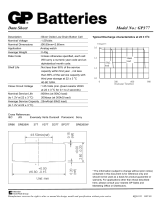
Filling and Emptying one common tank
Time
Fill Fill
Empty Empty
LL
SS
HH
LL
SS
H
System B
Emptying
H
System A
Filling
System A, Filling
Master
System B, Emptying
Slave
11
5
6
(PE)
7
8
9
11
5
6
REF
(PE)
7
8
9
Sync. in
Sync. out
Sync. in
Sync. out
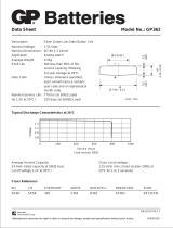
Filling and Emptying one common tank
System A
Master
System B
Slave
System C
Slave
REF
2
10
5
6
(PE)
7
8
9
1
3
111111
4
5
6
(PE)
7
8
9
5
6
(PE)
7
8
9
Sync.
out
Sync.
in
Sync.
in
Sync.
in
Sync.
out
Sync.
out
7
7
Level
Level
Relay C ON (1-3)
Relay C ON (1-3)
Relay B ON (1-3)
Relay B ON (1-3)
Relay A ON (1-3)
Relay A ON (1-3)
A6
A6
A5
A5
B6
B6
B5
B5
C6
C6
C5
C5
Power supply ON
Power supply ON
Emptying
Filling
Time
Time
Fill
Fill
Empty
Empty
L
L
S
S
H
H
L
L
S
S
H
H
Multilevel application in one tank
Relé di controllo del livello per liquidi conduttivi in grado di controllare
due livelli di riempimento o svuotamento.
Il relé ha una gamma di sensibilità da 250Ω a 500kΩ pari alla gamma da
4µ siemens a 2µ siemens.
Se sono necessari più di due livelli, è possibile aggiungere altri sistemi
• Controllore di livello conduttivo
• Regolazione della sensibilità – resistenza operativa da 250Ω a 500KΩ
• Per applicazioni di riempimento o svuotamento
• Elettrodi CA a bassa tensione
• Facile installazione con spina circolare a 11 pin
• Tensione operativa nominale: 24 VCA/CC, 115 VCC o 230 VCC
• Uscita a relé SPDT 8A/250 VCA
• Indicazione LED per: Uscita ON, Alimentazione ON
• Possibilità di connessione seriale
Descrizione del prodotto I
Specifiche
Tensione nominale operativa (U
B
)
Pin 2 & 10 230 da 95 a 265 VCA, da 45 a 65 Hz
115 da 98 a 132 VCA, da 45 a 65 Hz
Classe di alimentazione 2 24 da 19.2 a 28.8 VCA/CC
Tensione di isolamento nominale <2.0 kVCA (rms)
Tensione nominale di tenuta alle
scariche a impulso 4 kV (1.2/50 µs) (linea/neutro)
Classificazione relè (AgCdO) µ (micro gap)
Carichi resistivi CA1 8 A / 250 VCA (2500 VA)
CC1 1 A / 250 VCC (250 W) o
10 A / 25 VCC (250 W)
Piccoli carichi induttivi CA15 0,4 A / 250 VCA
CC13 0,4 A / 30 VCC
Durata meccanica (tipica) ≥ 30 x 10
6
operazioni
@ 18’000 imp/h
Durata elettrica (tipica) CA1 > 250’000 operazioni
Alimentazione sonda di livello Massimo 5 VCA
Corrente sonda di livello Massimo 2 mA
Sensibilità da 250Ωa 500KΩ
Gamma standard delle impo-
stazioni di fabbrica “S” 100KΩ
Gamme L (bassa sensibilità) da 250Ω a 5 KΩ, CF ≤ 4,7 nF
Gamme S (sensibilità standard) da 5 KΩ a 100 KΩ, CF ≤ 2,2 nF
Gamme H (alta sensibilità) da 50 KΩ a 500 KΩ, CF ≤ 1,0 nF
Frequenza operativa (f)
Uscita a relè 0.5 HZ
Grado di protezione IP 20 /CEI 60529, 60947-1)
Temperatura
Operativa da -20º a +50ºC
Conservazione da -50º a +85ºC
Approvazioni
UL cURus UL508
CSA CSA-C22.2 No.247
Marchio CE Sì
Cavo di collegamento
cavo a 2 o 3 conduttori in PVC, normalmente schermato. Lunghezza del
cavo: massimo 100 m. La resistenza tra il nucleo e la terra deve essere
almeno 500k. Normalmente, si consiglia di utilizzare un cavo schermato
tra sonda e controllore, ad esempio nel caso in cui il cavo venga posiz-
ionato in parallelo rispetto ai cavi di carico (di alimentazione). La sch-
ermatura deve essere collegata al pin 7 (riferimento).
Cascata
Se sono necessari più di 2 livelli, è possibile mettere fino a 7 amplificatori
in cascata, come indicato nell’esempio sottostante.
Collegare il pin 11 del controllore master a terra e il pin 9 del controllore
master al pin 8 del controllore successivo, i controllori slave (vedi dis-
egno). Il pin 11 del controllore slave deve rimanere aperto! Il pin 9 del
primo slave deve essere collegato al pin 8 del secondo. Il pin 9 dell’ultimo
slave deve essere collegato al pin 8 del master.
I collegamenti devono essere effettuati con cavo schermato per avere un
funzionamento ottimale, ad esempio nei cunicoli o nelle passerelle in cui
il cavo si trova vicino ai cavi di alimentazione. Collegare la schermatura
al pin 7 e accertarsi che la distanza tra due sistemi sia 3 m al massimo.
Regolare la sensibilità del sistema collegato e i sistemi sono pronti al
funzionamento.
Esempio 1
Il diagramma illustra il controllo di livello collegato come controllo
massimo e minimo. Il relè reagisce alla corrente alternata bassa che si
crea quando gli elettrodi sono a contatto con il liquido.
Il riferimento (Ref) deve essere collegato al contenitore o se nel conteni-
tore si trova un materiale non conduttivo, a un elettrodo aggiuntivo. (Da
collegare al pin 7).
(Nel diagramma questo elettrodo è indicato con la linea tratteggiata.)
NB!
Se è richiesto il rilevamento di un solo livello - interconnettere i due
ingressi 5 e 6.
Modalità di funzionamento
Niveaustyringsrelæ til leden de væsker. Kan styre to niveauer af påfyld-
ning eller tømning.
Relæets følsomhed spænder fra 250Ω til 500kΩ svarende til fra 4m sie-
mens til 2μ siemens.
Hvis mere end to niveauer er påkrævet, kan flere systemer tilføjes.
• Ledende niveaustyreenhed
• Justeringsfølsomhed - driftsmodstand fra 250Ω til 500 kΩ
• Til påfyldnings- eller tømningsenheder
• Lavspændingselektrode (AC)
• Nem installation med rundt 11-bens stik
• Nominelt spændingsområde: 24 VAC / DC, 115 VAC eller 230 VAC
• Udgang: 8A/250 V AC 1-polet relæ (SPDT)
• Lysdiodeindikation for: Udgang aktiveret, Power aktiveret
• Mulighed for seriel tilslutning
Produktbeskrivelse DK
Specifikationer
Nominelt spændingsområde (U
B
)
Ben 2 & 10 230 195 til 265 V AC, 45 til 65 Hz
115 98 til 132 V AC, 45 til 65 Hz
Forsyningsklasse 2 24 19,2 til 28,8 V AC/DC
Nominel isoleringsspænding <2,0 kV AC (rms)
Nominel stødspænding 4 kV (1,2/50 µs) (fase/neutral)
Relæbelastning (AgCdO) µ (mikrokontakt)
Ohmske belastninger AC1 8 A / 250 V AC (2500 VA)
DC1 1 A / 250 V DC (250 W)
or 10 A / 25 V DC (250 W)
Små induktive belastninger AC15 0,4 A / 250 V AC
DC13 0,4 A / 30 V DC
Mekanisk levetid (typisk) ≥ 30 x 10
6
aktiveringer
@ 18.000 impulser/time
Elektrisk levetid (typisk) AC1 > 250.000 aktiveringer
Niveaufølerforsyning Maks. 5 V AC
Niveaufølerstrøm Maks. 2 mA
Følsomhed 250Ω til 500KΩ
Fabriksindstilling “S” 100KΩ
Område L (Lav følsomhed) 250Ω til 5KΩ, CF ≤ 4,7 nF
Område S (Standard følsomhed) 5KΩ til 100KΩ, CF ≤ 2,2 nF
Område H (Høj følsomhed) 50KΩ til 500KΩ, CF ≤ 1,0 nF
Tastefrekvens (f)
Relæudgang 0,5 HZ
Tæthedsgrad IP 20 / IEC 60529, 60947-1)
Temperatur
Drift -20 º til +50 º C
Lager -50 º til +85 º C
Godkendelser
UL cURus UL508
CSA CSA-C22,2 Nr. 247
CE-mærkning Ja
Tilslutningskabel
2- eller 3-leder pvc-kabel, normalt skærmet. Kabellængde: maks. 100
m. Modstanden mellem kernerne og jord skal være mindst 50 k.mellem
kernerne ogjord skal være mindst 50 k.. Normalt anbefales det at bruge
et skærmet kabel mellem føler og styreenhed, f.eks. hvis kablet er pla-
ceret parallelt med belastningskablerne (strømforsyning). Afskærm ningen
skal tilsluttes ben 7 (reference).
Serieopkobling
Hvis der er behov for mere end to niveauer, kan op til syv forstærkere
serieopkobles, som det er vist i eksemplet herunder.
Slut ben 11 på den første styreenhed, master-styreenheden til jord,
og ben 9 på master-styreenheden til ben 8 på de næste styreenheder,
slavestyreenhederne (se teg ningen). Ben 11 på slaveenheden skal være
ubenyttet! Ben 9 i første slave skal forbindes til ben 8 på den anden. Ben
9 i sidste slave skal forbindes til ben 8 i Masteren.
Tilslutningerne skal foretages ved hjælp af skærmet kabel for at opnå
optimal drift, f.eks. i kabelbrønde eller kabelbakker, hvor kablet er tæt
på strømkabler. Slut afskærmningen til ben 7 og kontrollér at afstanden
mellem to systemer er højst 3 m.
Juster det tilsluttede systems følsomhed og systemerne er klar til funk-
tion.
Eksempel 1
Diagrammet viser niveau-styringen tilsluttet som maks. og min. styring.
Relæet reagerer på den lave vekselstrøm der skabes når elektroderne er
i kontakt med væsken.
Referencen (Ref) skal forbin des til beholderen, eller, hvis beholderen er
lavet af ikke-ledende materiale, til en ekstra elektrode. (Skal tilslut tes ben 7).
(I diagrammet er denne elektrode vist ved en stiplet linje).
Bemærk!
Hvis kun ét niveau er påkrævet, forbindes de to indgange 5 og 6 med
hinanden.
Funktionsbeskrivelse
Sync. in
Ref
Lo
Hi
Master (GND)
Slave (Not connected)
2
10
5
6
(PE)
7
8
9
1
3
11
4
Sync. out
If only one amplifier (no slave
amplifiers) - interconnect
terminal 7 and 11.
Eksempel 1
Filling and Emptying one common tank
Füllen und Entleeren im gemeinsamen Behälter
Remplissage et vidange d’un réservoir commun
Llenado y vaciado de un depósito común
Riempimento e svuotamento di un serbatoio comune
Påfyldning og tømning, én tank
Multilevel application in one tank
Mehrstands-Messung in einem Tank
Application de plusieurs dans un réservoir
Aplicación multinivel en un depósito
Applicazioni multilivello in un serbatoio
Flerniveau-opsætning i én tank
Power supply ON / Stromversorgung EIN / Alimentation électrique
MARCHE / Alimentación activada / Alimentatore ON / Strømforsyning
tændt
Level / Füllstand / Niveau / Nivel / Livello / Level
Time / Zeit / Temps / Tiempo / Tempo / Tid
Fill / Füllen / Remplir / Llenar / Riempi / Fylde
Empty / Leer / Vider / Vaciar / Svuota / Tømme
System X / System X / Système X / Sistema X / Sistema X / System X
Filling / Füllen / Remplissage / Llenado / Riempimento / Påfyldning
Emptying / Entleeren / Vidange / Vaciado / Svuotamento / Tømning
Master / Master / Maître / Maestro / Principale / Master
Slave / Slave / Esclave / Esclavo / Secondario / Slave
Relay X ON / Relais X EIN / Relais X MARCHE / Relé X activado /
Relé X ON / Relæ X ON
Sync. in
Ref
Lo
Hi
Master (GND)
Slave (Not connected)
2
10
5
6
(PE)
7
8
9
1
3
11
4
Sync. out
If only one amplifier (no slave
amplifiers) - interconnect
terminal 7 and 11.
Esempio 1
Maestro (GND)
Esclavo (Not Connected)
Sincron. in entrata
Sincron. in uscita
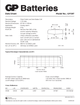
60,2
41,5
81
Dimensions / Maßzeichnungen / Dimensions /
Dimensiones / Disegni dimensionali / Dimensioner
35,5
4
5
6
7
8
9
10
111
2
3
HI LO
REF
Sync. in
Sync. out
GND*
Supply
Wiring Diagram / Shaltplan / Diagramme de
câblage / Diagrama de conexiones / Schema
elettronico / Forbindelsesdiagram
Bottom view / Ansicht von unten / Vue de dessous / Vista inferior /
Vista dal basso / Set nedefra
* Master: connect to ground. Slave: do not connect / * Master: An
Masse (GND) anschließen. Slave: nicht anschließen (NC) / * Maître:
Raccordement à la terre. Esclave: non raccordé / * Maestro: conec-
tar a GND. Esclavo: no conectar / * Master : collegare a terra.
Slave : non collegare / * Master: Tilslut til jord (GND). Slave: Tilslut ikke
Hvis der kun er én forstærker
(ingen slaveforstærkere),
forbindes klemme 7 og 11.
In caso di utilizzo di un solo
amplificatore ( nessun disposi-
tivo slave presente ) collegare i
terminali 7 e 11
Master: GND
Slave: Ikke tilsluttet
/