Page is loading ...

1/15 Installation & Operating Manual MN438
Nuclear Service Class 1E
Nuclear Service Non-Class 1E
Integral and Fractional Horsepower
AC Induction Motors
TENV, TEFC Enclosures
48 – 449 Frame

Any trademarks used in this manual are the property of their respective owners.
Important:
Be sure to check www.baldor.com to download the latest version of this manual in Adobe Acrobat PDF format.

iMN438
Table of Contents
Section 1
General Information ................................................................. 1-1
Overview ....................................................................... 1-1
Limited Warranty ................................................................. 1-1
Safety Notice ................................................................... 1-1
Receiving ...................................................................... 1-2
Handling ........................................................................ 1-2
Storage ........................................................................ 1-3
Preparation for Storage ........................................................ 1-4
Removal From Storage ......................................................... 1-4
Section 2
Installation & Operation .............................................................. 2-1
Overview ....................................................................... 2-1
Location ........................................................................ 2-1
Mounting Location ................................................................ 2-1
Frame Mounting Holes ......................................................... 2-2
Power Connection ................................................................ 2-3
Grounding .................................................................. 2-3
Conduit Box ................................................................. 2-3
AC Power ................................................................... 2-4
Rotation ................................................................... 2-4
Connection Diagrams .......................................................... 2-5
Initial Lubrication ................................................................. 2-7
First Time Start Up ............................................................... 2-7
Coupled Start Up ................................................................. 2-8
Jogging and Repeated Starts ....................................................... 2-8
Section 3
Maintenance & Troubleshooting ....................................................... 3-1
General Inspection ................................................................ 3-1
Relubrication & Bearings .......................................................... 3-1
Type of Grease
Relubrication Intervals ......................................................... 3-2
Relubrication Procedure ....................................................... 3-4
Troubleshooting Chart ............................................................ 3-5
Suggested bearing and winding RTD setting guidelines for Non−Hazardous Locations ONLY ..... 3-6

ii MN438

General Information 1-1MN438
Section 1
General Information
Overview This manual contains general procedures that apply to Baldor Motor products. Be sure to read and understand
the Safety Notice statements in this manual. For your protection, do not install, operate or attempt to perform
maintenance procedures until you understand the Warning and Caution statements.
A Warning statement indicates a possible unsafe condition that can cause harm to personnel.
A Caution statement indicates a condition that can cause damage to equipment.
Important: This instruction manual is not intended to include a comprehensive listing of all details for all
procedures required for installation, operation and maintenance. This manual describes general
guidelines that apply to most of the motor products shipped by Baldor. If you have a question about a
procedure or are uncertain about any detail, Do Not Proceed. Please contact your Baldor distributor for
more information or clarification.
Limited Warranty
www.baldor.com/support/warranty_standard.asp
Baldor Nuclear-class Motors are categorized as “Denite Purpose AC Motors”
Safety Notice: This equipment contains high voltage! Electrical shock can cause serious or fatal injury. Only qualified
personnel should attempt installation, operation and maintenance of electrical equipment. Be sure
that you are completely familiar with NEMA publication MG-2, safety standards for construction and
guide for selection, installation and use of electric motors and generators, the National Electrical Code
and local codes and practices. Unsafe installation or use can cause conditions that lead to serious or
fatal injury. Only qualified personnel should attempt the installation, operation and maintenance of this
equipment.
WARNING: Do not touch electrical connections before you first ensure that power has been disconnected.
Electrical shock can cause serious or fatal injury. Only qualified personnel should attempt the
installation, operation and maintenance of this equipment.
WARNING: Be sure the system is properly grounded before applying power. Do not apply AC power before you
ensure that all grounding instructions have been followed. Electrical shock can cause serious or fatal
injury. National Electrical Code and Local codes must be carefully followed.
WARNING: Avoid extended exposure to machinery with high noise levels. Be sure to wear ear protective devices to
reduce harmful effects to your hearing.
WARNING: This equipment may be connected to other machinery that has rotating parts or parts that are driven by
this equipment. Improper use can cause serious or fatal injury. Only qualified personnel should attempt
to install operate or maintain this equipment.
WARNING: Do not by-pass or disable protective devices or safety guards. Safety features are designed to prevent
damage to personnel or equipment. These devices can only provide protection if they remain operative.
WARNING: Avoid the use of automatic reset devices if the automatic restarting of equipment can be hazardous to
personnel or equipment.
WARNING: Be sure the load is properly coupled to the motor shaft before applying power. The shaft key must be
fully captive by the load device. Improper coupling can cause harm to personnel or equipment if the
load decouples from the shaft during operation.
WARNING: Use proper care and procedures that are safe during handling, lifting, installing, operating and
maintaining operations. Improper methods may cause muscle strain or other harm.
WARNING: Before performing any motor maintenance procedure, be sure that the equipment connected to the
motor shaft cannot cause shaft rotation. If the load can cause shaft rotation, disconnect the load from
the motor shaft before maintenance is performed. Unexpected mechanical rotation of the motor parts
can cause injury or motor damage.
WARNING: Disconnect all electrical power from the motor windings and accessory devices before disassembly of
the motor. Electrical shock can cause serious or fatal injury.
WARNING: Do not use non UL/CSA listed explosion proof motors in the presence of flammable or combustible
vapors or dust. These motors are not designed for atmospheric conditions that require explosion proof
operation.
WARNING: This equipment is at line voltage when AC power is connected. Disconnect and lockout all ungrounded
conductors of the AC power line before proceeding. Failure to observe these precautions could result in
severe bodily injury or loss of life.
WARNING: Surface temperatures of motor enclosures may reach temperatures which can cause discomfort or
injury to personnel accidentally coming into contact with hot surfaces. When installing, protection
should be provided by the user to protect against accidental contact with hot surfaces. Failure to
observe this precaution could result in bodily injury.
WARNING: Thermostat contacts automatically reset when the motor has slightly cooled down. To prevent injury or
damage, the control circuit should be designed so that automatic starting of the motor is not possible
when the thermostat resets.
WARNING: Rotating parts can cause serious or fatal injury. If relubrication is performed with the motor running, to
avoid injury do not contact any rotating parts.
WARNING: Solvents can be toxic and/or flammable. Follow manufacturer’s safety procedures and directions.
Failure to observe this precaution could result in bodily injury.
Continued on next page.

1-2 General Information MN438
Safety Notice Continued
WARNING: Pacemaker danger − Magnetic and electromagnetic fields in the vicinity of current carrying carrying
conductors and permanent magnet motors can result result in a serious health hazard to persons
with cardiac pacemakers, metal implants, and hearing aids. To avoid risk, stay way from the area
surrounding a permanent magnet motor.
WARNING: Use of an air jet may cause flying debris and generate particulate matter. Wear suitable skin, eye and
respiratory protection. Failure to observe these precautions may result in bodily injury.
WARNING: Space Heaters operate at line voltage. Disconnect power to space heaters before performing
maintenance work on motor. Failure to observe this precaution could result in severe bodily injury or
loss of life.
WARNING: Thermostat contacts automatically reset when the motor has slightly cooled down. To prevent injury or
damage, the control circuit should be designed so that automatic starting of the motor is not possible
when the thermostat resets.
WARNING: Baldor Nuclear-class motors must only be repaired by a factory-authorized nuclear service motor
service center to maintain the original factory Environmental Qualification. Due to the critical nature of
these motors it is important that the motors be dismantled, repaired, and reassembled consistent with
original manufacturing procedures using original factory materials for certain components.
Caution: Only Chevron SRI No. 2 and ExxonMobil Polyrex EM greases have been Environmentally Qualified for
use in Baldor Nuclear-class motors having ball or roller bearings. Do not use other grease types.
Caution: To avoid damage to the windings do not use air pressures greater than 30 psi (200 kPa). Avoid directing
the air in such a way that the dirt will be blown into inner crevices.
Caution: To prevent premature equipment failure or damage, only qualified maintenance personnel should
perform maintenance.
Caution: Do not over−lubricate motor as this may cause premature bearing failure. Over−lubricating can cause
excessive bearing temperatures, premature lubrication breakdown and bearing failure.
Caution: Do not lift the motor and its driven load by the motor lifting hardware. The motor lifting hardware is
adequate for lifting only the motor. Disconnect the load from the motor shaft before moving the motor.
Caution: The lifting direction should not exceed a 45° angle from the lifting angle. Excessive lifting angles can
cause damage.
Caution: To prevent equipment damage, be sure that the electrical service is not capable of delivering more than
the maximum motor rated amps listed on the rating plate.
Caution: If a HI POT test (High Potential Insulation test) must be performed, follow the precautions and procedure
in NEMA MG1 and MG2 standards to avoid equipment damage.
Caution: To avoid damage to motor bearings, grease must be kept free of dirt. For an extremely dirty
environment, contact your local Baldor District Office for additional information.
Caution: Do not use solvents containing trichloroethane to clean interior or exterior of motor. Damage may
occur to paint and insulation systems.
If you have any questions or are uncertain about any statement or procedure, or if you require additional
information please contact your Baldor distributor or an Authorized Baldor Service Center.
Receiving Each Baldor Nuclear-class Motor is thoroughly tested at the factory and carefully packaged for shipment.
Where specied, Class 1E motors are packaged in accordance with NQA-1, Part II, Subpart 2.2 Level B for
shipment. When the motor is received, there are several things that should be done immediately. Do not
unpack until ready for use.Observe the condition of the shipping container and report any damage immediately
to the commercial carrier that delivered your motor.
1. Observe the condition of the shipping container and report any damage immediately to the commercial
carrier that delivered the motor.
2. Verify that the part number of the motor received is the same as the part number listed on the purchase
order.
3. Class 1E motors should be placed in a NQA-1, Level B storage facility until installed on the driven
equipment.
Handling The motor should be lifted using the lifting lugs or eye bolts provided.
Caution: Do not lift the motor and its driven load by the motor lifting hardware. The motor lifting hardware is
adequate for lifting only the motor. Disconnect the load (gears, pumps, compressors, or other driven
equipment) from the motor shaft before lifting the motor.
1. Use the lugs or eye bolts provided to lift the motor. Never attempt to lift the motor and additional
equipment connected to the motor by this method. The lugs or eye bolts provided are designed to lift only
the motor. Never lift the motor by the motor shaft.
2. To avoid condensation inside the motor, do not unpack until the motor has reached room temperature.
(Room temperature is the temperature of the room in which it will be installed). The packing provides
insulation from temperature changes during transportation.
3. If the motor must be mounted to a plate with the driven equipment such as pump, compressor etc., it may
not be possible to lift the motor alone. For this case, the assembly should be lifted by a sling around the
mounting base. The entire assembly can be lifted as an assembly for installation. Do not lift the assembly

General Information 1-3MN438
using the motor lugs or eye bolts provided. Lugs or eye bolts are designed to lift motor only. If the load is
unbalanced (as with couplings or additional attachments) additional slings or other means must be used
to prevent tipping. In any event, the load must be secure before lifting. If the load is unbalanced (as with
couplings or additional attachments) additional slings or other means must be used to prevent tipping. In
any event, the load must be secure before lifting
Storage The following storage requirements should be observed for motors that will not be placed into service for at
least six months from the date of shipment. Improper motor storage will result in seriously reduced reliability
and failure. An electric motor that does not experience regular usage while being exposed to normally humid
atmospheric conditions is likely to develop rust in the bearings, or rust particles from surrounding surfaces may
contaminate the bearings. The electrical insulation may absorb an excessive amount of moisture leading to
the motor winding failure.
Motors packaged in accordance with NQA-1 Level B requirements should be stored in their original containers
in a clean, dry, protected warehouse that complies with the requirements of NQA-1 Level B. For motors with
standard commercial packaging, a wooden crate “shell” should be constructed to secure the motor during
storage. This is similar to an export box, but the sides & top must be secured to the wooden base with lag
bolts (not nailed as export boxes are) to allow opening and reclosing many times without damage to the
“shell”.
Minimum resistance of motor winding insulation is 5 Meg ohms or the calculated minimum, which ever is
greater. Minimum resistance is calculated as follows: Rm = kV + 1
where: (Rm is minimum resistance to ground in Meg−Ohms and kV is rated nameplate
voltage dened as Kilo−Volts.)
Example: For a 480VAC rated motor Rm =1.48 meg−ohms (use 5 M Ω).
Preparation for Storage
1. Some motors have a shipping brace attached to the shaft to prevent damage during transportation.
The shipping brace, if provided, must be removed and stored for future use. The brace must be reinstalled
to hold the shaft rmly in place against the bearing before the motor is moved.
2. Store in a clean, dry, protected warehouse where control is maintained as follows:
a. Shock or vibration must not exceed 2 mils maximum at 60 hertz, to prevent the bearings from
brinelling. If shock or vibration exceeds this limit vibration isolation pads must be used.
b. Storage temperatures of 10 ºC (50 ºF) to 49 ºC (120 ºF) must be maintained.
c. Relative humidity must not exceed 60%. Desiccants or other humidity control methods should be
used to minimize condensation in and around the motor.
d. Minimize the accumulation of condensed water in and around the machine.
e. Motor space heaters (when present) are to be connected and energized whenever there is a possibility
that the storage ambient conditions will reach the dew point. Space heaters are optional.
Note: Remove motor from containers when heaters are energized, reprotect if necessary.
3. Measure and record the resistance of the winding insulation (dielectric withstand) every 30 days of storage.
a. If motor insulation resistance decreases below the minimum resistance, contact your Baldor District
ofce.
b. Place new desiccant inside the vapor bag and re−seal by taping it closed.
c. If a zipper−closing type bag is used instead of the heat−sealed type bag, zip the bag closed instead
of taping it. Be sure to place new desiccant inside bag after each monthly inspection.
d. Place the shell over the motor and secure with lag bolts.
4. Where motors are mounted to machinery, the mounting must be such that the drains and breathers are
fully operable and are at the lowest point of the motor. Vertical motors must be stored in the vertical
position. Storage environment must be maintained as stated in step 2.
5. Motors with anti−friction bearings are to be greased at the time of going into extended storage with
periodic service as follows:
a. Motors marked “Do Not Lubricate” on the nameplate do not need to be greased before or during
storage.
b. Ball and roller bearing (anti−friction) motor shafts are to be rotated manually every 3 months and
greased every 6 months in accordance with the Maintenance section of this manual.

1-4 General Information MN438
6. All breather drains are to be fully operable while in storage (drain plugs removed). The motors must be
stored so that the drain is at the lowest point. All breathers and automatic “T” drains must be operable to
allow breathing and draining at points other than through the bearings around the shaft. Vertical motors
should be stored in a safe stable vertical position.
7. Coat all external machined surfaces with a rust preventing material.
An acceptable product for this purpose is Exxon Rust Ban # 392.
Non−Regreaseable Motors
Non−regreasable motors with “Do Not Lubricate” on the nameplate should have the motor shaft rotated
15 times to redistribute the grease within the bearing every 3 months or more often.
All Other Motor Types
Before storage, the following procedure must be performed.
1. Remove the grease drain plug, if supplied, (opposite the grease tting) on the bottom of each bracket prior
to lubricating the motor.
2. Motor with regreasable bearings must be greased as instructed in Section 3 of this manual.
3. Replace the grease drain plug after greasing.
4. The motor shaft must be rotated a minimum of 15 times after greasing.
5. Motor Shafts are to be rotated at least 15 revolutions manually every 3 months and additional grease
added to each bearing every nine months (see Section 3).
6. Bearings are to be greased at the time of removal from storage.
Removal From Storage
1. Remove all packing material.
2. Measure and record the electrical resistance of the winding insulation to ground with an insulation
resistance meter. If the winding insulation resistance is above the acceptable minimum, the motor may be
placed into service. A decrease in winding resistance below the acceptable minimum indicates moisture
in the windings and necessitates electrical or mechanical drying before the motor can be placed into
service. If the winding resistance is below the acceptable minimum, contact your Baldor District ofce.
3. For storage periods exceeding 24 months, a thorough bearing inspection and visual inspection of the
stator winding and motor leads is required.
4. Regrease the bearings as instructed in Section 3 of this manual.
5. Reinstall the original shipping brace if motor is to be moved. This will hold the shaft rmly against the
bearing and prevent damage during movement.

Installation & Operation 2-1MN438
Section 2
Installation & Operation
Overview Installation should conform to the National Electrical Code as well as local codes and practices. When other
devices are coupled to the motor shaft, be sure to install protective devices to prevent future accidents.
Some protective devices include, coupling, belt guard, chain guard, shaft covers etc. These protect against
accidental contact with moving parts. Machinery that is accessible to personnel should provide further
protection in the form of guard rails, screening, warning signs etc.
Location The Baldor Nuclear-class motors described in this instruction manual are offered in Totally Enclosed, Severe
Duty constructions only and may be installed either indoors or outdoors in installations with high corrosion
or excessive moisture conditions. These motors should not be placed into an environment where there is the
presence of ammable or combustible vapors, dust or any combustible material unless specically designed
for this type of service in accordance with local codes and standards.
Proper ventilation for the motor must be provided. Obstructed airow can lead to reduction of motor life.
Caution: Class 1E motors have been designed for specific applications in the nuclear power plant. These motors
must be installed in the locations for which they were originally purchased. Environmental and Seismic
Qualification of these motors is based on the parameters given for these locations.
Mounting Location
To allow adequate air ow, the following clearances must be maintained between the motor and any
obstruction:
Table 2-1 Enclosure Clearance
TEFC Enclosures
Fan Cover Air Intake 48 – 140T Frame, 1” (25 mm)
180 – 210T Frame, 1” (25 mm)
250 – 449T Frame, 4” (100 mm)
Exhaust Envelope equal to the P Dimension on the motor
dimension sheet
The motor must be securely installed to a rigid foundation or mounting surface to minimize vibration and
maintain alignment between the motor and shaft load. Failure to provide a proper mounting surface may cause
vibration, misalignment and bearing damage.
Foundation caps and sole plates are designed to act as spacers for the equipment they support. If these
devices are used, be sure that they are evenly supported by the foundation or mounting surface.
When installation is complete and accurate alignment of the motor and load is accomplished, the base should
be grouted to the foundation to maintain this alignment.
The standard motor base is designed for horizontal or vertical mounting. Adjustable or sliding rails are
designed for horizontal mounting only. Consult your local Baldor District Ofce for further information.
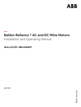
Frame Mounting Holes
Some motors have standardized frames containing 6 or 8 mounting holes. 6 hole frames are not suitable for
eld reversal of mounting from F−1 to F−2, etc. Figure 2-1 indicates the proper mounting holes to use.
Figure 2-1 6 & 8 Hole Motor Frame Mounting
Caution: Do not lift the motor and its driven load by the motor lifting hardware. The motor lifting hardware is
adequate for lifting only the motor. Disconnect the load (gears, pumps, compressors, or other driven
equipment) from the motor shaft before lifting the motor.
Top View
Allows F-1 to F-2 Conversion on 8 hole
frames.
Not present on 6 hole frames.
Not used on 8 hole frames.
Shaft
Always use these holes, closer to the
shaft 112S, 132S, 160M, 180M,
200M, 225S, 250S, 280S, (IEC)
For short frame designations 182, 213,
254, 284, 324, 364, 404, 444 (NEMA)
For long frame designations 184, 215,
256, 286, 326, 365, 405, 445 (NEMA)
(IEC) 112M, 132M, 160L, 200L, 225M,
250M, 280M

2-2 Installation & Operation MN438
In the case of assemblies on a common base, any lifting means provided on the motor should not be used
to lift the assembly and base but, rather, the assembly should be lifted by a sling around the base or by other
lifting means provided on the base. Assure lifting in the direction intended in the design of the lifting means.
Likewise, precautions should be taken to prevent hazardous overloads due to deceleration, acceleration or
shock forces.
Alignment Accurate alignment of the motor with the driven equipment is extremely important. The pulley, sprocket,
or gear used in the drive should be located on the shaft as close to the shaft shoulder as possible. It is
recommended to heat the pulley, sprocket, or gear before installing on the motor shaft. Forcibly driving a unit
on the motor shaft will damage the bearings.
1. Direct Coupling
For direct drive, use exible couplings if possible. Consult the drive or equipment manufacturer for more
information. Mechanical vibration and roughness during operation may indicate poor alignment. Use dial
indicators to check alignment. The space between coupling hubs should be maintained as recommended
by the coupling manufacturer.
2. End-Play Adjustment
The axial position of the motor frame with respect to its load is also extremely important. The standard
motor bearings are not designed for excessive external axial thrust loads. Improper adjustment will cause
failure.
3. Pulley Ratio
The best practice is to not exceed an 8:1 pulley ratio.
Caution: Do not over tension belts. Excess tension may damage the motor or driven equipment.
4. Belt Drive
Align sheaves carefully to minimize belt wear and axial bearing loads (see End-Play Adjustment). Belt
tension should be sufcient to prevent belt slippage at rated speed and load. However, belt slippage may
occur during starting.
Doweling & Bolting
After proper alignment is veried, dowel pins should be inserted through the motor feet into the foundation.
This will maintain the correct motor position should motor removal be required.
(Baldor•Reliance motors are designed for doweling.)
1. Drill dowel holes in diagonally opposite motor feet in the locations provided.
2. Drill corresponding holes in the foundation.
3. Ream all holes.
4. Install proper tting dowels.
5. Mounting bolts must be carefully tightened to prevent changes in alignment. Use a at washer and lock
washer under each nut or bolt head to hold the motor feet secure. Flanged nuts or bolts may be used as
an alternative to washers.
WARNING: Guards must be installed for rotating parts such as couplings, pulleys, external fans, and unused shaft
extensions, should be permanently guarded to prevent accidental contact by personnel.
Accidental contact with body parts or clothing can cause serious or fatal injury.
Guarding Guards must be installed for rotating parts such as couplings, pulleys, external fans, and unused shaft
extensions. This is particularly important where the parts have surface irregularities such as keys, key ways or
set screws. Some satisfactory methods of guarding are:
1. Covering the machine and associated rotating parts with structural or decorative parts of the driven
equipment.
2. Providing covers for the rotating parts. Covers should be sufciently rigid to maintain adequate guarding
during normal service.
Power Connection
Motor and control wiring, overload protection, disconnects, accessories and grounding should conform to the
National Electrical Code and local codes and practices. After the motor is unpacked, examine the nameplate
data to see that it agrees with the circuit to which it is to be connected. The motor as a minimum will fully meet
the requirements outlined in NEMA MG-1 20.14 including any special voltage and frequency requirements
imposed by the contract between Baldor and its Customer.
Grounding In the USA consult the National Electrical Code, Article 430 for information on grounding of motors and
generators, and Article 250 for general information on grounding. In making the ground connection, the installer
should make certain that there is a solid and permanent metallic connection between the ground point, the
motor terminal housing, and the motor frame if frame grounding provisions are available. In non−USA locations
consult the appropriate national or local code applicable.

Installation & Operation 2-3MN438
Motors with resilient cushion rings usually must be provided with a bonding conductor across the resilient
member. Some motors are supplied with the bonding conductor on the concealed side of the cushion ring to
protect the bond from damage. Motors with bonded cushion rings should usually be grounded at the time of
installation in accordance with the above recommendations for making ground connections. When motors
with bonded cushion rings are used in multi-motor installations employing group fusing or group protection,
the bonding of the cushion ring should be checked to determine that it is adequate for the rating of the branch
circuit over current protective device being used.
There are applications where grounding the exterior parts of a motor may result in greater hazard by increasing
the possibility of a person in the area simultaneously contacting ground and some other nearby live electrical
parts of other ungrounded electrical equipment. In portable equipment it is difcult to be sure that a positive
ground connection is maintained as the equipment is moved, and providing a grounding conductor may lead to
a false sense of security. When careful consideration of the hazards involved in a particular application indicate
the machine frames should not be grounded or when unusual operation conditions dictate that a grounded
frame cannot be used, the installer should make sure the machine is permanently and effectively insulated
from ground. In those installations where the machine frame is insulated from ground, it is recommended that
appropriate warning labels or signs be placed be placed on or in the area of the equipment by the installer.
Conduit Box For ease of making connections, an oversize conduit box is provided. Most conduit boxes on motor frame
sizes 180 and larger can be rotated 360 º in 90 º increments. Auxiliary conduit boxes are provided on some
motors for accessories such as space heaters, RTD’s etc.
AC Power Motors with ying lead construction must be properly terminated and insulated.
Connect the motor leads as shown on the connection diagram located on the name plate or inside the cover
on the conduit box. Be sure the following guidelines are met:
1. AC power is within +10% of rated voltage with rated frequency. (See motor name plate for ratings).
OR
2. AC power is within +5% of rated frequency with rated voltage.
OR
3. A combined variation in voltage and frequency of +10% (sum of absolute values) of rated values, provided
the frequency variation does not exceed +5% of rated frequency.
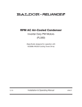
Performance within these voltage and frequency variations are shown in Figure 2-3.
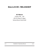
Figure 2-2 Accessory Connections
Rotation All three phase motors are reversible. To reverse the direction of rotation, disconnect and lock out power and
interchange any two of the three line leads for three phase motors. Adjustable Frequency Power Inverters used
to supply adjustable frequency power to induction motors produce wave forms with lower order harmonics
with voltage spikes superimposed. Turn−to−turn, phase−to−phase, and ground insulation of stator windings
are subject to the resulting dielectric stresses. Suitable precautions should be taken in the design of these
drive systems to minimize the magnitude of these voltage spikes. Consult the drive instructions for maximum
acceptable motor lead lengths, and proper grounding.
Caution: The space heaters are designed to operate at or below the maximum surface temperature stated on the
nameplate. If the marked ambient and/or voltage are exceeded this maximum surface temperature can
be exceeded and can damage the motor windings. If applied in a division 2 or zone 2 environment this
excessive temperature may cause ignition of hazardous materials.
One heater is installed in each end of motor.
Leads for each heater are labeled H1 & H2.
(Like numbers should be tied together).
Three thermistors are installed in windings and tied in series.
Leads are labeled TD1 & TD2.
Winding RTDs are installed in windings (2) per phase.
Each set of leads is labeled
1TD1, 1TD2, 1TD3, 2TD1, 2TD2, 2TD3 etc.
* One bearing RTD is installed in Drive endplate (PUEP), leads
are labeled RTDDE.
* One bearing RTD is installed in Opposite Drive endplate (FREP), leads
are labeled RTDODE.
* Note RTD may have 2−Red/1−White leads; or 2−White/1−Red Lead.
TD1
TD2

2-4 Installation & Operation MN438
Connection Diagrams

Installation & Operation 2-5MN438
Connection Diagrams Continued

2-6 Installation & Operation MN438
Figure 2-3 Typical Motor Performance VS Voltage Variations
Initial Lubrication
Baldor Nuclear-class Motors are shipped from the factory with the bearings properly packed with grease and
ready to operate. Where the unit has been subjected to extended storage (6 months or more) the bearings
should be re-lubricated (regreaseable type) prior to starting.
First Time Start Up
Be sure that all power to motor and accessories is off. Be sure the motor shaft is disconnected from the load
and will not cause mechanical rotation of the motor shaft.
1. Make sure that the mechanical installation is secure. All bolts and nuts are tightened etc.
2. If motor has been in storage or idle for some time, check winding insulation integrity.
3. Inspect all electrical connections for proper termination, clearance, mechanical strength and electrical
continuity.
4. Be sure all shipping materials and braces (if used) are removed from motor shaft.
5. Manually rotate the motor shaft to ensure that it rotates freely.
6. Replace all panels and covers that were removed during installation.
7. Momentarily apply power and check the direction of rotation of the motor shaft.
8. If motor rotation is wrong, be sure power is off and change the motor lead connections.
Verify rotation direction before you continue.
9. Start the motor and ensure operation is smooth without excessive vibration or noise.
If so, run the motor for 1 hour with no load connected.
10. After 1 hour of operation, disconnect power and connect the load to the motor shaft.
Verify all coupling guards and protective devices are installed. Ensure motor is properly ventilated.
11. If motor is totally enclosed fan−cooled or non−ventilated it is recommended that condensation drain plugs,
if present, be removed. These are located in the lower portion of the end−shields. Totally enclosed fan−
cooled “XT” motors are normally equipped with automatic drains which may be left in place as received.
+20
+15
+10
+5
0
−5
−10
−15
−20
−15 −10 −5 0 +5 +10 +15
Voltage Variations (%)
Changes in Motor Performance (%)
Full -Load
Current
Full -Load
Current
Power
Factor
Power
Factor
Efficiency
Efficiency
Maximum
Torque
Maximum
Torque

Installation & Operation 2-7MN438
Coupled Start Up
This procedure assumes a coupled start up. Also, that the rst time start up procedure was successful.
1. Check the coupling and ensure that all guards and protective devices are installed.
2. Check that the coupling is properly aligned and not binding.
3. The rst coupled start up should be with no load. Apply power and verify that the load is not transmitting
excessive vibration back to the motor though the coupling or the foundation.
Vibration should be at an acceptable level.
4. Run for approximately 1 hour with the driven equipment in an unloaded condition.
The equipment can now be loaded and operated within specied limits. Do not exceed the name plate ratings
for amperes for steady continuous loads.
Jogging and Repeated Starts
Repeated starts and/or jogs of induction motors generally reduce the life of the motor winding insulation.
A much greater amount of heat is produced by each acceleration or jog than by the same motor under full
load. If it is necessary to repeatedly start or jog the motor, it is advisable to check the application with your
local Baldor distributor or Baldor Service Center.
Heating - Duty rating and maximum ambient temperature are stated on the motor name plate.
Do not exceed these values. If there is any question regarding safe operation, contact your local Baldor
distributor or Baldor Service Center.
WARNING: The user is responsible for conformation with the National Electrical Code and all other applicable
local codes. Wiring practices, grounding, disconnects, and over-current protection are of particular
importance. Failure to observe these precautions could result in severe bodily injury or loss of life.
WARNING: Ensure that all guards are properly installed before proceeding. Exercise extreme care to avoid
contacting rotating parts. Failure to observe these precautions could result in bodily injury.
WARNING: Rotating parts such as couplings, pulleys, external fans, and unused shaft extensions should be
permanently guarded against accidental contact with hands or clothing. This is particularly important
where the rotating parts have surface irregularities such as keys, keyways, or set-screws.
Operation: Due to the inherent characteristics of insulating materials, abnormally high temperatures shorten the operating
life of electrical apparatus. The total temperature, not the temperature rise, should be the measure of safe
operation. Aging of insulation occurs at an accelerated rate at abnormally high temperatures.
Unbalanced voltage or single-phase operation of poly-phase machines may cause excessive heating and
ultimate failure. It requires only a slight unbalance of voltage applied to a poly-phase motor to cause large
unbalanced currents and resultant overheating.
Periodic checks of phase voltage, frequency and power consumption of a motor while in operation are
recommended; such checks ensure the correctness of frequency and voltage applied to the motor and yield an
indication of the load offered by the apparatus which the motor drives. Comparisons of this data with previous
no-load and full-load power demands will give an indication of the performance of the complete machine. Any
serious deviations should be investigated and corrected.

2-8 Installation & Operation MN438

Maintenance & Troubleshooting 3-1MN438
Section 3
Maintenance & Troubleshooting
Caution: Baldor Nuclear-class motors must only be repaired by a factory-authorized nuclear service motor
service center to maintain the original factory Environmental Qualification. Due to the critical nature of
these motors it is important that the motors be dismantled, repaired, and reassembled consistent with
original manufacturing procedures using original factory materials for certain components.
Periodic Inspection
Baldor Nuclear-class motors should be inspected at regular intervals, approximately every 500 hours of
operation or every 3 months, whichever occurs rst. Class 1E motors must be inspected periodically to
maintain qualication. Keep the motors clean and the ventilation openings clear. The following steps should be
performed at each inspection:
WARNING: Do not touch electrical connections before you first ensure that power has been disconnected.
Electrical shock can cause serious or fatal injury. Only qualified personnel should attempt the
installation, operation and maintenance of this equipment.
1. Check that the motor is clean. Check that the interior and exterior of the motor is free of dirt, oil, grease,
water, etc. Oily vapor, paper pulp, textile lint, etc. can accumulate and block motor ventilation. If the motor
is not properly ventilated, overheating can occur and cause early motor failure.
2. Perform a dielectric with stand test periodically to ensure that the integrity of the winding insulation has
been maintained. Record the readings. Immediately investigate any signicant decrease in insulation
resistance.
3. Check all electrical connectors to be sure that they are tight.
Relubrication & Bearings
Bearing grease will lose its lubricating ability over time, not suddenly. The lubricating ability of a grease (over
time) depends primarily on the type of grease, the size of the bearing, the speed at which the bearing operates
and the severity of the operating conditions. Good results can be obtained if the following recommendations
are used in your maintenance program.
Caution: Only Chevron SRI No. 2 and ExxonMobil Polyrex EM greases have been Environmentally Qualified for
use in Baldor Nuclear-class motors having ball or roller bearings.
Relubrication Intervals
Recommended relubrication intervals are shown in Table 3-1. It is important to realize that the recommended
intervals of Table 3-2 are based on average use.
Refer to additional information contained in Tables 3-2, 3-3 and 3-4.
Table 3-1 Relubrication Intervals *
NEMA Frame Size
Rated Speed - RPM
3600** 1800 1200 900
48 – 210 incl. 5,500 Hrs. 12,000 Hrs. 18,000 Hrs. 22,000 Hrs.
Over 210 to 280 incl. 3,600 Hrs. 9,500 Hrs. 15,000 Hrs. 18,000 Hrs.
Over 280 to 360 incl. *2,200 Hrs. 7,400 Hrs. 12,000 Hrs. 15,000 Hrs.
Over 360 to 449 incl. *2,200 Hrs. 3,500 Hrs. 7,400 Hrs. 10,500 Hrs.
* Relubrication intervals are for ball bearings.
For vertically mounted motors and roller bearings, divide the relubrication interval by 2.
** For motors operating at speeds greater than 3600 RPM, contact Baldor for relubrication
recommendations.

3-2 Maintenance & Troubleshooting MN438
Table 3-2 Service Conditions
Severity of Service Hours per day of
Operation
Ambient Temperature
Maximum
Atmospheric Contamination
Standard 8 40 ºC Clean, Little Corrosion
Severe 16 Plus 50 ºC Moderate dirt, Corrosion
Extreme 16 Plus 65° C Severe dirt, Abrasive dust, Corrosion,
Heavy Shock or Vibration
Table 3-3 Relubrication Interval Multiplier
Severity of Service Multiplier
Standard 1.0
Severe 0.5
Extreme 0.1
Some motor designs use different bearings on each motor end. This is normally indicated on the motor
nameplate. In this case, the larger bearing is installed on the motor Drive endplate. For best relubrication
results, only use the appropriate amount of grease for each bearing size (not the same for both).
Table 3-4 Bearings Sizes and Types
Frame Size
NEMA (IEC)
Bearing Description (“Large” / Drive End)
Bearing
Weight of Grease to
add * oz (Grams)
Volume of grease to be added
in
3
teaspoon
48 to 140 6203 0.08 (2.4) 0.15 0.5
140 6205 0.15 (3.9) 0.2 0.8
180 6206 0.19 (5.0) 0.3 1.0
210 6307 0.30 (8.4) 0.6 2.0
250 6309 0.47 (12.5) 0.7 2.5
280 6311 0.61 (17) 1.2 3.9
320 6312 0.76 (20.1) 1.2 4.0
360 6313 0.81 (23) 1.5 5.2
400 6316 1.25 (33) 2.0 6.6
440 6318 1.52 (40) 2.5 8.2
440 6319 2.12 (60) 4.1 13.4
360 to 449 NU319 2.12 (60) 4.1 13.4
* Weight in grams = .005 DB of grease to be added
Note: Not all bearing sizes are listed. For intermediate bearing sizes, use the grease volume for the next larger
size bearing.
Caution: To avoid damage to motor bearings, grease must be kept free of dirt. For an extremely dirty
environment, contact your Baldor distributor or an authorized Baldor Service Center for additional
information.

Maintenance & Troubleshooting 3-3MN438
Relubrication Procedure
Caution: Only Chevron SRI No. 2 and ExxonMobil Polyrex EM greases have been Environmentally Qualified for
use in Baldor Nuclear-class motors having ball or roller bearings. Do not use other grease types.
Caution: Do not over−lubricate motor as this may cause premature bearing failure. Over−lubricating can cause
excessive bearing temperatures, premature lubrication breakdown and bearing failure.
With Grease Outlet Plug
1. With the motor stopped, clean all grease ttings with a clean cloth.
2. Remove grease outlet plug.
3. Add the recommended amount of grease.
4. Operate the motor for 15 minutes with grease plug removed. This allows excess grease to purge.
5. Re-install grease outlet plug.
Without Grease Provisions
Caution: Baldor Nuclear-class motors must only be repaired by a factory-authorized nuclear service motor
service center to maintain the original factory Environmental Qualification. Due to the critical nature of
these motors it is important that the motors be dismantled, repaired, and reassembled consistent with
original manufacturing procedures using original factory materials for certain components.
The motor must be returned to a factory-authorized nuclear service motor center for all maintenance.

3-4 Maintenance & Troubleshooting MN438
Table 3-5 Troubleshooting Chart
Symptom Possible Causes Possible Solutions
Motor will not start
Usually caused by line trouble, such as,
single phasing at the starter.
Check source of power. Check overloads, fuses,
controls, etc.
Excessive humming
High Voltage.
Eccentric air gap.
Check input line connections.
Have motor serviced at local Baldor service center.
Motor Over Heating
Overload. Compare actual amps
(measured) with nameplate rating.
Locate and remove source of excessive friction in motor
or load.
Reduce load or replace with motor of greater capacity.
Single Phasing. Check current at all phases (should be approximately
equal) to isolate and correct the problem.
Improper ventilation. Check external cooling fan to be sure air is moving
properly across cooling ns.
Excessive dirt build-up on motor. Clean motor.
Unbalanced voltage. Check voltage at all phases (should be approximately
equal) to isolate and correct the problem.
Rotor rubbing on stator. Check air gap clearance and bearings.
Tighten “Thru Bolts”.
Over voltage or under voltage. Check input voltage at each phase to motor.
Open stator winding. Check stator resistance at all three phases for balance.
Grounded winding. Perform dielectric test and repair as required.
Improper connections. Inspect all electrical connections for proper termination,
clearance, mechanical strength and electrical continuity.
Refer to motor lead connection diagram.
Bearing Over Heating
Misalignment. Check and align motor and driven equipment.
Excessive belt tension. Reduce belt tension to proper point for load.
Excessive end thrust. Reduce the end thrust from driven machine.
Excessive grease in bearing. Remove grease until cavity is approximately 3/4 lled.
Insufcient grease in bearing. Add grease until cavity is approximately 3/4 lled.
Dirt in bearing. Clean bearing cavity and bearing. Repack with correct
grease until cavity is approximately 3/4 lled.
Vibration
Misalignment. Check and align motor and driven equipment.
Rubbing between rotating parts and
stationary parts.
Isolate and eliminate cause of rubbing.
Rotor out of balance. Have rotor balance checked are repaired at your Baldor
Service Center.
Resonance. Tune system or contact your Baldor Service Center for
assistance.
Noise
Foreign material in air gap or ventilation
openings.
Remove rotor and foreign material. Reinstall rotor. Check
insulation integrity. Clean ventilation openings.
Growling or whining
Bad bearing. Replace bearing. Clean all grease from cavity and new
bearing. Repack with correct grease until cavity is
approximately 3/4 lled.
/