Page is loading ...

Installation
Manual
Model: X7
This device complies with part 15 of the FCC rules. Operation is subject to the following two conditions:
(1) This device may not cause harmful interference; and
(2) This device must accept any interference received, including interference that may cause undesired operation.
Note: The manufacturer is not responsible for any radio or TV interference caused by unauthorized modifications to this
equipment. Such modifications could void the user’s authority to operate the equipment.
For Technical Assistance, please call (800) 638-3600,
or visit www.magnadyne.com

Table of Contents
Installer Warnings . . . . . . . . . . . . . . . . . . . . . . . . . . . . . . . . . . . . . . . . . . . . . . . . 3
Component Placement . . . . . . . . . . . . . . . . . . . . . . . . . . . . . . . . . . . . . . . . . . . . . 4
Wiring Harness Quick Reference . . . . . . . . . . . . . . . . . . . . . . . . . . . . . . . . . . . . . 5-6
Wiring
Starter and Power Harness Wiring . . . . . . . . . . . . . . . . . . . . . . . . . . . . . . . . . . 7-8
Door Lock Output Wiring . . . . . . . . . . . . . . . . . . . . . . . . . . . . . . . . . . . . . . . . . 9-12
Accessory Alarm and Remote Start Wiring . . . . . . . . . . . . . . . . . . . . . . . . . . . 13-17
Plug Port Information . . . . . . . . . . . . . . . . . . . . . . . . . . . . . . . . . . . . . . . . . . . . . 18-20
Transmitter Programming . . . . . . . . . . . . . . . . . . . . . . . . . . . . . . . . . . . . . . . . . . 21
Alarm Feature Programming . . . . . . . . . . . . . . . . . . . . . . . . . . . . . . . . . . . . . . . . 22-25
Remote Start Feature Programming . . . . . . . . . . . . . . . . . . . . . . . . . . . . . . . . . . 26-27
Engine Crank Detection Programming . . . . . . . . . . . . . . . . . . . . . . . . . . . . . . . . . 28-29
Remote Start Shutdown Diagnostics . . . . . . . . . . . . . . . . . . . . . . . . . . . . . . . . . . 30
Return to Factory Default Settings . . . . . . . . . . . . . . . . . . . . . . . . . . . . . . . . . . . . 30
Safety Testing the Installation . . . . . . . . . . . . . . . . . . . . . . . . . . . . . . . . . . . . . . . 31
Wiring Diagram . . . . . . . . . . . . . . . . . . . . . . . . . . . . . . . . . . . . . . . . . . . . . . . . . . 32
2

3
• Due to the complexity of this system, installation must only be performed by a qualified
professional installer. This remote start and alarm system is NOT a “Do It Yourself” product.
• This remote starter and alarm system is designed to be installed on fuel injected gasoline or diesel
vehicles with an automatic transmission ONLY. Installation of this system on a vehicle with a
manual transmission (Stick Shift) is dangerous and is contrary to it’s intended use.
• This system must be installed and wired through a safety switch so it will not start the engine
while in any forward or reverse gear. This is normally accomplished by connecting the systems
provided safety wire to the vehicles electronic Neutral Safety switch located on the transmission
shifter.
• Some automatic transmission vehicles may have a mechanical type park safety lock system
instead of electrical safety switch. This mechanical type system does not interrupt the starter
circuit when the transmission is any gear and does not offer the 100% level of safety required for
remote starting purposes. The next best safety connection point on this type of vehicle would be
the vehicle parking brake switch. This requires the user to set the parking brake prior to activating
the remote starting system.
• Once you install this system, you must verify that the vehicle will not start in any forward or
reverse gear. Regardless of the type of vehicle.
• Do not install any component near the brake, gas pedal or steering linkage.
• Some vehicles have a factory installed transponder immobilizer system that can severely
complicate the installation. There is a possibility that this system can not be installed on some
immobilizer equipped vehicles.
• Most vehicles have an SRS air bag system. Use extreme care and do not probe any wires of the
SRS system. Disconnect the vehicle (+) or (-) battery cable before installing this system on the
vehicle.
• Use conventional crimp lock type connectors on all low current wiring connections. Poor wiring,
i.e. taped joints, will introduce unreliability into the remote start and alarm system and may result
in false alarms, incorrect or failed operation.
• All wires that operate at currents higher than 10A should be soldered to insure a long lasting
connection.
• Install wiring neatly under carpets or behind trim to prevent possible damage to wires.
• For dealer technical assistance, please call (800) 638-3600 or visit www.magnadyne.com
Installer Warnings

Windshield Receiver/Antenna
• The combination windshield receiver/antenna mounts on the windshield (inside).
• We suggest you mount it on the lower left-hand side of the windshield.
Warning! Do not mount in such a manner that it obstructs the driver’s view.
• The receiver/antenna whip can be vertical or horizontal.
1. Remove the protective tape backing.
2. Carefully align the receiver/antenna and apply to windshield.
3. Route the black connecting cable behind the trim and connect to receiver/antenna.
4. Connect the other end to the control module.
4
Component Placement
Dual-Zone Shock Sensor
Select a mounting location within the passenger's compartment or trunk. Do not mount in the engine
compartment or in any location where it will get wet, greasy or will be subject to heat, direct or indirect. To
achieve the best overall level of protection, select a mounting location that is centrally located in the vehicle. It
will be necessary for the shock sensor to be somewhat accessible to make the correct sensitivity adjustment.
The mounting surface should be as flat as possible for best sensitivity. The sensor can be mounted in any
position as long as it is solidly mounted.
Valet Switch
Select a mounting location for the switch that is easily accessible to the driver of the vehicle. The switch does
not have to be concealed, however, concealing the switch is always recommended, as this provides an even
higher level of security to the vehicle. Mount the valet switch in a hidden but accessible location. Route the valet
switch wires to the control module.
LED Status Indicator
The LED indicator status should be mounted in a highly visible area. Leave at least 6mm of space behind the
mounting location for LED housing. Once a suitable location is chosen, drill a 1/4" hole. Run the LED wires
through the hole then press the 2-pin LED housing into the place. Route the LED wires to the control module.
Mount the antenna horizontally for
best reception.

HC1 6-Pin Remote Start Harness
Violet Remote Starter Output
Red +12VDC Battery Input #1
Yellow +Ignition 1 Output
Red +12VDC Battery Input #1
Brown +ACC / Heater-Air Conditioner Output
Pink +Ignition 2 / ACC 2 Output
HC2 5-Pin Power Input Harness
Red/White Park Light Relay Input
Black Chassis Ground
Brown (+) Programmable Output (Siren - Default)
White Parking Light Relay Output
Red +12VDC Battery Input
HC3 3-Pin Door Lock Harness
Green (-) Lock / (+) Unlock Output
Light Blue Programmable Output (2nd Unlock Default)
Blue (-) Unlock / (+) Lock Output
5
Wiring Harness Quick Reference

HC4 7-Pin Accessory Harness
Violet/White Tach Input
Green (-) Common Door Pin Input
Violet (+) Common Door Pin Input
Blue (-) Hood/Trunk Alarm Pin Input
Gray (-) Remote Start Hood Pin Safety Input
Brown (+) Brake Switch Input
Black/White (-) Neutral Safety Switch Input
HC5 5-Pin Accessory Harness
Violet/Yellow (-) Start #2 Output
Pink (-) Ignition #3 Output
Blue/White (-) Defroster Output
Black/White (-) Programmable Output (Dome Lt - Default)
Red/White (-) Channel #3 Output
6
Wiring Harness Quick Reference

HC1: White 6-Pin High Current Remote Starter Harness
The method that the remote starter uses to start the vehicle is a duplicate of the ignition switch
function. Below, is an explanation of the 3 basic functions of the ignition switch. Since this
installation will require analysis of the ignition switch functions, it is recommended that you
make the three connections below at the ignition switch harness directly.
Careful consideration for the connection of this wire must be made to prevent the vehicle from starting while in
gear. Understanding the difference between a mechanical and an electrical Neutral Start Switch will allow you to
properly identify the circuit and select the correct installation method. In addition you will realize why the
connection of the safety wire is required for all mechanical switch configurations.
WARNING! Failure to make this connection properly can result in personal injury and property damage.
In all installations it is the responsibility of the installing technician to test the remote start unit and assure that
the vehicle can not start via RF control in any gear selection other than park or neutral.
In both mechanical and electrical neutral start switch configurations, the connection of the Violet wire will be
made to the low current start solenoid wire of the ignition switch harness. This wire must have +12 volts when
the ignition switch is turned to the “START” (crank) position only. This wire have 0 volts in all other ignition
switch positions.
Note: If a starter disable relay is installed, the connection of the violet wire must be at the starter side of the
relay, not the ignition switch side.
Failure to connect this wire to the ignition switch side of the neutral safety switch can result in personal injury
and property damage (See Neutral Start Safety Test for further details).
Remove the two 20A fuses prior to connecting these wires and do not replace them until the harness has been
plugged into the control module. These wires are the source of current for all the circuits the relay harness will
energize. They must be connected to a high current source. Connection to 12V battery terminal recommended.
Connect the Yellow wire to the ignition 1 wire from the ignition switch. The ignition wire should receive
+12 volts when the ignition key is in the “ON” or “RUN” and “START” or “CRANK” position. When the ignition is
turned “OFF”, the ignition wire should receive “0” voltage. The yellow wire must be connected.
"ACC"
"START"
"OFF" "ON"
Starter
Start Cut Relay
(When Used)
Violet Wire
Closed in Park
or Netral Only
Neutral Safety Switch
6-Pin
White Connector
7
Wiring
Violet Wire: Starter Output
Red Wires (2): +12V Power Input
Yellow Wire: Ignition 1 Output

HC1: White 6-Pin High Current Remote Starter Harness (continued)
Some vehicles have 2 ignition wires that must be powered. Connect the “Pink” wire to the ignition 2 wire from
the ignition switch. No connection required on vehicles without second ignition.
Connect the Brown wire to the accessory wire that powers the climate control system. An accessory wire will
show +12 volts when the ignition switch is turned to the “ACCESSORY” or “ON” and “RUN” positions, it will
show 0 volts when the key is turned to the “OFF” and “START” or “CRANK” position. There will often be more
than one accessory wire in the ignition harness. The correct accessory wire will power the vehicle’s climate
control system. Some vehicles may have separate wires for the blower motor and the air conditioning
compressor. In such cases, it will be necessary to add a relay to power the second accessory wire.
HC2: White 5-Pin Power Harness
The Red/White wire has already been assembled to work with a +12 volt switched parking light system (most
vehicles). For vehicles with ground switched parking light activation cut this wire and connect it to ground.
Connect the White wire to the parking light wire coming from the headlight switch. Do not connect the White
wire to the dashboard lighting dimmer switch (damage to the dimmer will result). The limitation of the White
wire is 10 amp maximum. Do not exceed this limit or damage to the alarm and parking relay will result.
This is main ground connection of the alarm module. Make this connection to a solid section of the vehicle
chasis. Do not connect this wire to any existing ground wires supplied by the factory wire loom, make the
connection to the vehicle’s chasis directly.
By default, the Brown wire is the positive (+) output
connection for the siren. Current capacity is 2 amps.
Make connection to the (+) red wire from the siren.
Connect the (-) black wire coming from the siren to a
good chassis ground.
Option: (+) Horn Output (See “Alarm Feature
Programming” to change the function to horn)
Connect this wire to the existing vehicle’s horn relay
trigger. Some vehicle horn systems may be (-) trigger
and a relay will need to be added for proper operation
as shown.
The “Red” wire supplies power to the system. Connect this wire to a constant +12 volt source.
87
87a
86
85
30
Brown
Wire
To Ground
To Horn
+12V or Ground
Depending on
System Requirements
Fuse
White
5-Pin
Connector
8
Wiring (continued)
Pink Wire: Ignition 2 Output
Brown Wire: Accessory Output, Heater/AC Output
Red/White Stripe: Parking Light Relay Input
White Wire: Parking Light Relay Output, + or - Selectable
Black Wire: System Ground
Brown Wire: (+) Programmable Output - Siren Default Setting
Red Wire: System Power, +12V Constant

9
HC3: Black 3-Pin Door Lock Harness
Wiring (continued)
If the door lock control system on the vehicle is (-) type, connect the Blue wire to the unlock wire from the door
lock switch . If the door lock control system on the vehicle is (+) type, connect the Blue wire to the lock wire
from the door lock switch.
If the door lock control system on the vehicle is (-) type, connect the Green wire to the lock wire from the door
lock switch . If the door lock control system on the vehicle is (+) type, connect the Green wire to the unlock wire
from the door lock switch.
Driver’s Door Priority 2nd Unlock Output:
By default the Light Blue wire provides a second (-) unlock output to unlock the passenger’s doors. Follow the
diagrams on pages 10-12 for proper connection.
Factory Security Disarm Output:
The Light Blue wire can be programmed to provide a (-) pulse output every time the X7 is disarmed. This
connection can be used to disarm the vehicles factory security system at the same time the X7 is disarmed.
See Alarm Feature Programming (Group 3), page 24.
Start Status Output:
The Light Blue wire can be programmed to provide a constant (-) output during the time that the vehicles
engine is running under the control of the X7. In this configuration, the Light Blue wire can be used as sensor
bypass control. Connect a relay to the sensor power wire and use the Light Blue wire to trigger the relay. See
Alarm Feature Programming (Group 3), page 24.
Blue Wire: (+/-) Door Lock Control
Green Wire: (+/-) Door Lock Control
Light Blue Wire: (-) Programmable Accessory Wire
3 Wire Positive Trigger Door Lock System
(+) Lock Out
+12 Volts Input
(+) Unlock Out
To Door Lock
Control Relays
Blue Wire: Connect to Lock
Green Wire: Connect to Unlock
Lock Control
Switch
Black 3-Pin
Mini Connector
3 Wire Ground Trigger Door Lock System
(
-
) Lock Out
Ground Input
(
-
) Unlock Out
To Door Lock
Control Relays
Lock Control
Switch
Blue Wire: Connect to Unlock
Green Wire: Connect to Lock
Black 3-Pin
Mini Connector

10
HC3: Black 3-Pin Door Lock Harness
(continued)
Unlock Driver's Door First Wiring for 5-Wire Ground at Rest Door Locking Systems
87
87A
85
86
30
87
87A
85
86
30
To +12 Volts
(Battery +)
To Power
Lock Switch
To Power
Lock Motors
Lock
Lock
Unlock
Unlock
87
87A
85
86
30
+ Unlock
Cut
Driver's
Door Motor
Green Wire
Blue Wire
Light Blue Wire
Newly Installed Power Door Lock Motors
87
87A
85
86
30
87
87A
85
86
30
To +12 Volts
(Battery +)
To Ground
To Newly
Installed Power
Door Lock Motors
White Wire
Brown Wire
Green Wire: Lock
Blue Wire: Unlock
Violet Wire
ALA-DL1
Relay Pack
Red Wire: Lock
Black Wire: Unlock
Black 3-Pin Connector
Green Wire
Blue Wire
Note: Orange wire from ALA-DL1
must be connected to +12V
Wiring (continued)

Mercedes Door Lock Activation
Door Lock
Switch
Unlock
Lock
B+
87
87A
85
86
30
87
87A
85
86
+
++
To +12 Volts
(Battery +)
Door Lock
Compressor
Cut
Green Wire
Unlock
Lock
Black 3-Pin
Mini Connector
Green Wire: Lock
Blue Wire: Unlock
Unlock Driver's Door First for 3-Wire Negative Door Lock Systems
87
87A
85
86
30
Unlock Wire
Passenger's Door
Lock
Unlock
To +12V or Ground
To +12V or Ground
Driver's Door
Rear Doors
Passenger's
Door Switch
Door Lock Relay
Control Module
Lock
Unlock
+12V
ALA984H
Relay
Driver's Door
Switch
Cut
Blue Wire
Green Wire
Light Blue Wire
HC3: Black 3-Pin Door Lock Harness
(continued)
Unlock Driver's Door First Wiring for 3-Wire Positive Door Lock System
87
87A
85
86
30
To +12 Volts
(Battery +)
To Power Door
Lock Switch
Lock/Unlock Wires
Lock
Unlock
87
87A
85
86
30
+ Unlock
Cut
Driver's
Door Motor
Black 3-Pin
Mini Connector
Green Wire
Blue Wire
Light Blue Wire
Wiring (continued)
11

12
HC3: Black 3-Pin Door Lock Harness
(continued)
5 Wire Ground at Rest Door Locking Systems
87
87A
85
86
30
87
87A
85
86
30
To +12 Volts
(Battery +)
To Power
Lock Switch
To Power
Lock Motors
White Wire: Lock
Brown Wire: Unlock
Green Wire: Lock
Blue Wire: Unlock
Violet Wire
ALA-DL1
Relay Pack
Red Wire: Lock
Black Wire: Unlock
Black 3-Pin
Mini Connector
Green Wire
Blue Wire
Note:
Orange wire from ALA-DL1
must be connected to +12V
White Wire Lock
To Power
Lock Switch
To Power
Lock Motors
Brown Wire Unlock
Green Wire Lock
Blue Wire Unlock
Violet Wire To +12 Volts Constant
Lock Fuse 1
Unlock Fuse 2
ALA-DL1
Red Wire
Black Wire
Black 3-Pin
Mini Connector
Green Wire
Blue Wire
Note: Orange wire from ALA-DL1 must be connected to +12V.
Wiring (continued)
One Wire Multiplexing Door Locking Systems
Some vehicle’s (Chrysler, Mazda and Ford Probe and others) use one wire to lock and unlock the doors.
Example: When the door lock controller sees a signal thru a resistor it will unlock. If a signal is received
without a resistor the doors will lock. Some use 2 resistors. One for lock and one for unlock. We have
developed patented plug-in fuse resistors for this application. Simply remove the fuse from our door lock
module and replace with correct resistor value fuses that matches the vehicles door lock switch.
Wiring:
1. Connect both the green (lock) and the blue (unlock) wires to the vehicles one wire lock/unlock wire.
2. Connect our violet polarity input wire to +12v or to ground. To match vehicles door lock polarity.
3. The white and the brown wires will not be used.

13
Wiring (continued)
Black
7-Pin Mini
Connector
Brake Light
Bulbs
+12 Volts
Switch Closes when
Brake is Depressed
Brown Wire
Brake
Pedal
To Lights
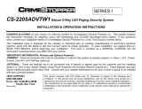
HC4: Black 7-Pin Accessory Harness
This wire is the ground trigger input wire for hood/trunk pin switches.
The Green wire is the ground trigger input wire for negative door pin switch.
The Violet wire is the positive trigger input wire for positive door pin switch.
Brown Wire: Positive Safety Shut Down Input
Blue Wire: (-) Instant Trigger Wire
Green Wire: (-) Door Trigger
Violet Wire: (+) Door Trigger
Gray Wire: (-) Hood Safety Shut Down Input
This wire provides instant shutdown for the remote start, when it receives +12 volts. If the brake lights switch in
the vehicle switches +12 volts to the brake light circuit, connect this wire to the output side of the brake switch.
This will allow the remote start to shut down if an attempt is made to operate the vehicle without the key while
running under the control of the remote start. A relay may be required if the brake light switch is (-) type.
The Gray wire provides instant shutdown for the remote start when it is grounded. Connect the Gray wire to an
existing hood pin switch or install the one provided in this kit. This wire must be routed through a grommet in the
firewall and connected to the hood pin switch. If the hood pin switch is also to be used as an alarm system trigger,
diodes are required as shown.
Important! This connection is a
safety wire and must be connected
as shown and tested as specified.
Failure to do so may result in
personal injury or property damage.
Note: The Gray wire can also be
used as the “Brake Safety”
connection if the vehicle brake light
circuit switches a ground signal to
the brake lights. An isolation diode
must be used and connected to the
output of the brake switch.
Hood Pin Switch
Gray Wire
Negative Safety
Diode Diode
To Alarm Instant
Trigger Blue Wire

14
Wiring (continued)
HC4: Black 7 Pin Accessory Harness (continued)
The Black/White wire is a safety input wire. The remote start unit will not activate unless this wire is grounded.
When this wire is disconnected from ground, the remote start system is disabled.
1. The primary connection point for the Black/White wire is at the Neutral Safety Switch located on/at the transmission
shifting lever. The switch output must be GROUNDED when the shifter lever is in the PARK position.
2. The second best connection point for the Black/White wire is at the Parking Brake Switch output wire. Make
sure that when the parking brake is engaged that the output wire of the switch is grounded.
3. An optional remote start toggle switch can be added to temporarily disable the Remote Start Device. It can
prevent the vehicle from being remote started accidentally. This feature is useful if the vehicle is being
serviced or stored in an enclosed area. To disable the remote start, move the optional remote start enable
toggle switch to the OFF position. To enable the remote start, move the optional remote start enable toggle
switch to the ON position.
Note: When the Black/White wire is not used for it’s intended safety purpose, connect the
Black/White wire to the “Ground” or remote start system will not function.
This input provides the remote start system with information about the engine’s revolutions per minute (RPM).
It can be connected to the negative side of the coil in vehicle with conventional coils.
In multi-coil ignition system, the system can have individual coil wires. Individual coil wires in a multi-coil
ignition system will register lower amounts of AC voltage. Common locations for a tachometer wire are the
ignition coil itself, the back of the gauges, engine computers, and automatic transmission computers.
Note: This wire requires programming (See “Remote Start Feature Programming” for the proper programming
procedure).
Important! Do not test tachometer wires with a test light or logic probe. Electronic
components of the ignition system will be damaged. You must us a Digital Multi-meter.
Note: If you use the voltage or timer checking method for remote start detection, this wire does not need to be
connected.
How to find a tachometer wire with your multi-meter:
1. Set the meter to read ACV or AC voltage (12 or 20V).
2. Attach the (-) probe of the meter to chassis ground.
3. Start the vehicle’s engine.
4. Probe the wire you suspect of being the tachometer wire with the red probe (+) of the meter.
5.
If the probed wire is the correct wire, the meter will read between 1V and 6V at idle and will increase with RPM.
Black/White Wire
Neutral Safety Switch Input
P
R
N
2
1
Optional Enable Switch
Ignition
Electronic Control Module (ECM)
Solid State,
Do Not Measure Resistance
Black 7-Pin
Mini Connector
Black/White Wire: (-) Neutral Safety Switch Input
Violet Wire: (-) Tachometer Signal Connection

15
Wiring (continued)
Transponder Key
87
87A
85
86
30
Ignition Switch
+12 Volt Ignition
Pink Wire
White 5-Pin Mini Connector
HC5: White 5-Pin Accessory Harness
Some late model vehicles require (2)
START outputs from the ignition key
to start the vehicle. The Violet/Yellow
wire will become grounded when the
remote start is activated. This is a low
current output wire and will require a
30a/40a relay (not supplied) for
correct operation. Wire the relay as
shown.
Some newer vehicles use a third ignition
wire which is required to start and keep
the vehicle’s engine running. The Pink
wire provides a 200mA (-) ground
output that becomes active 4 seconds
before the remote start unit initializes.
This wire remains grounded while the
engine is running. This is a low current
output wire and will require a 30a/40a
relay (not supplied) for correct
operation. Wire the relay as shown.
Note: This wire can an also be used to control an ignition immobilizer bypass module.
Transponder Interfacing Using ALA984 Relay: Can also use optional RS-TIM bypass module.
If the vehicle has transponder system installed, you will need to bypass the system while the vehicle is operating
under the control of the Remote Start Unit. To do this, follow these steps:
1. You will need a transponder key that’s already programmed to the vehicle.
2. Remove the trim around the ignition switch.
3. Wrap a thin (30 awg) wire tightly around ignition switch 6 to 8 times and secure it.
4. About 6" down line make another loop of approximately 2" diameter.
5. Place the key inside this loop and secure it to the loop.
6. Connect on end of the 30 awg wire to pin (87) of the relay module.
7. Connect the other end of the loop wire to Pin (30) of relay module.
8. Connect (86) to ignition, connect (85) to the Yellow wire of 5-pin mini white connector.
87
87a
86
85
30
Violet/Yellow
Wire
+12 V Constant
Fused 25A Capable
Second Start Wire from
Ignition Key Switch
White
5-Pin Mini
Connector
87
87a
86
85
30
Pink
Wire
+12 V Constant
Fused 25A Capable
Ignition 3 Wire from
Ignition Key Switch
White
5-Pin Mini
Connector
Pink Wire : (-) 200mA Ignition 3 Output
Violet/Yellow Wire: (-) Second Start Output

16
Wiring (continued)
GM VATS Key Override Using ALA984:
Can also use RS-PLM bypass module.
Passkey/Vats: Anti-Theft Bypass
87
87A
85
86
30
To Ignition
White 5-Pin
Mini Connector
Passkey Wire Computer Side
Orange or Black Plastic Tube
at Steering Column
Resistor
Cut
Passkey Wire Key Side
Pink Wire
HC5: White 5 Pin Accessory Harness
(continued)
Resistor
Yellow
Trucks: Orange/Black or Cars: Black
Passkey II Passive Anti-Theft Bypass
87
87A
85
86
30
To Vehicle's Ignition Wire
Trucks: Red/White or Cars: White
White 5-Pin
Mini Connector
Pink Wire
Pink Wire : (-) 200mA Ignition 3 Output

17
Wiring
(continued)
HC5: White 5-Pin Accessory Harness (continued)
Dome Light Control Output :
This wire becomes grounded when the alarm is
disarmed. The current capacity of this wire is
200mA. This wire can control the operation of the
interior lights. Use of optional relay as shown is
recommended.
A. Upon disarming, the interior lights will remain
on for 30 seconds.
B. If the vehicle is violated, the interior light will
flash for the same duration as the siren.
Horn Output (See “Alarm Feature Programming”):
This wire can be used to activate the existing
vehicle’s horn as the alarm system’s optional
warning audible device. It’s a transistorized low
current output, and should only be connected to
the low current ground output from the vehicle’s
horn switch. When the system is triggered, the
horn will sound (depending on the vehicle’s
requirement an additional relay may be required as
shown).
Factory Security Rearm Signal Output (See “Alarm Feature Programming”):
This wire can be used to rearm a factory installed security system. This wire will supply a pulse whenever the
remote start times out or is shut down using the transmitter and remote door locking.
Ground Output During Crank (See “Alarm Feature Programming”):
This wire can be used to control another device as needed when the remote start is cranking the engine.
This wire will supply a constant ground while the engine is cranking.
The Blue/White will pulse a ground signal when the vehicle is running by remote starter. Locate the defroster
trigger wire at the back of the defrost switch and make the connection.
The Red/White will become grounded for
1 second when activated by the remote trans-
mitter. The current capacity of this wire is
200mA and may require an additional relay to
operate properly.
87
87a
86
85
30
Black/White
Wire
White
5-Pin Mini
Connector
+12V
Courtesy
Light
Door
Switch
Fuse
+12 Volts or Ground Depending
on Vehicle Requirement
Black/White Wire : (-) 200mA Programmable Output (Dome Light Supervision Default)
Blue/White Wire : (-) Defroster Output
Red/White Wire : Channel 3 (Trunk Release) Output
87
87a
86
85
30
To Horn
+12V or Ground
Depending on
System Requirements
Fuse
+12V
Black/White
Wire
White
5-Pin Mini
Connector
87
86
85
30
(Relay Not Supplied)
Output to Power
Trunk Switch
To Constant +12 Volts
Input to Relay (+ or
-
)
White
5-Pin Mini
Connector
Red/White
Wire

18
P3
Start Disable
P4
Sensor 1
P5
Sensor 2
P4 Sensor #1 and P5 Sensor #2
P3 Starter Disable (Ground when Armed)
Plug-In Ports
2-Stage Sensor:
Allows easy connection with quick disconnect ability for
other optional devices.
1. Red: +12 Volt Constant Input
2. Black: Main Sensor Ground
3. Blue: Instant Trigger (-) Input
4. Green: Warn Away (-) Input
Starter Disable Wiring Using ALA-RPS Relay Pack
Using the wiring information and diagram below, connect the optional starter disable relay as follows:
A. Locate the “Start Only Wire” coming from the ignition key switch and cut it.
B. Connect the ends of the cut start wire to the black wires coming from the ALA-RPS relay pack.
C. Plug in the orange 2-pin plug into the orange socket located on the alarm module.
To test the starter disable system refer to the starter disable testing procedures located in the testing section of
this manual.
87
87a
86
85
30
"ACC" "START"
"OFF" "ON"
Cut Black
Starter
ALA-RPS
Relay Pack
Red Wire
(Ign. Switched +12VDC)
Black Wire
(Ground when Armed Alarm Output)
Black
Violet Wire
6-Pin
White Connector

19
P6 Antenna / Receiver
Plug-In Ports (continued)
P1 Status LED Indicator
P2 Valet Switch
P1
LED
P2
Valet
P6
Antenna/Receiver

20
Black Wire No Connection
Red Wire No Connection
DBI Conection Harness (supplied)
P7 Data Adapter Communication
Plug-In Ports (continued)
P7
DBI
Data Interface Harness:
Allows direct communication between Marksman Remote Start and the vehicle’s data bus communication.
(Data Interface Modules sold separately)
Note: The DBI Connection Harness provides power and ground to the Data Interface Module. Do not connect
power and ground from Data Interface Module Harness.
/