Tektronix WVR6020 Quick start guide
- Category
- Supplementary music equipment
- Type
- Quick start guide
This manual is also suitable for

WVR6020, WVR7020, WVR7120,
WVR6100 Opt. MB, WVR7000 Opt. MB,
and WVR7100 Opt. MB
Waveform Rasterizers
ZZZ
Quick Start User Manual
xx
www.tektronix.com
071-2231-02

Copyright © Tektronix. All rights reserved. Licensed software products are owned by Tektronix or its subsidiaries or suppliers, and are
protected by na
tional copyright laws and international treaty provisions.
Tektronix prod
ucts are covered by U.S. and foreign patents, issued and pending. Information in this publication supersedes that in all
previously published material. Specifications and price change privileges reserved.
TEKTRONIX and TEK are registered trademarks of Tektronix, Inc.
Contacting Tektronix
Tektronix, Inc.
14200 SW Karl Braun Drive
P.O. Box 500
Beaverton, OR 97077
USA
For product information, sales, service, and technical support:
In North America, call 1-800-833-9200.
Worldwide, visit www.tektronix.com to find contacts in your area.

Warranty 2
Tektronix warrants that this product will be free from defects in materials and workmanship for a period o f one (1) year from the date of
shipment. If any such product proves defective during this warranty period, Tektronix, at its option, either will repair the defective
product without charge for parts and labor, or w ill provide a replacement in exchange for the defective product. Parts, modules and
replacement products used by Tektronix for warranty work may be new or reconditioned to like new performance. All replaced
parts, modules and products become the property of Tektronix.
In order to obtain service under this warranty, Customer must notify Tektronix of the defect before the expiration of the warranty period
and make suitable arrangements for the performance of service. Customer shall be responsible for packaging and shipping the
defective product to the service center designated by Tektronix, with shipping charges prepaid. Tektronix shall pay for the return of the
product to Customer if the shipment is to a location within the country in which the Tektronix service center is located. Customer shall
be responsible for paying all shipping charges, duties, taxes, and any other charges for products returned to any other locations.
This warranty shall not apply to any defect, failure or damage caused by improper use or improper or inadequate maintenance and
care. Tektronix shall not be obligated to furnish service under th is warranty a) to repair damage resulting from attempts by personnel
other than Tektronix representatives to install, repair or service the product; b) to repair damage resulting from improper use or
connection to incompatible equipment; c) to repair any damage or malfunction caused by the use of non-Tektronix supplies; or
d) to service a product that has been modified or integrated with other products when the effect of such modification or integration
increases the time or difficulty of s ervicing the product.
THIS WARRANTY IS GIVEN BY TEK TR ON IX WITH RESPECT TO TH E PRODUCT IN LIEU OF ANY OTHER WARRANTIES,
EXPRESS OR IMPLIED. TEKTRONIX AND ITS VENDO RS DISCLAIM ANY IMPLIED WARRANTIES OF MERCHANTABILITY OR
FITNESS FOR A PARTICULAR PURPOSE. TEKTRONIX’ RESPON SIBILITY TO REPAIR OR REPLACE DEFECTIVE PRODUCTS
IS THE SOLE AND EXCLUSIVE REME DY PROVIDED TO THE CUSTOMER FOR BR EAC H OF THIS WARRANTY. TEKTRONIX
AND ITS VENDORS WILL N OT BE LIABLE FOR ANY INDIRECT, SPECIAL, INCIDENTAL, OR CONSEQUENTIAL DAMAGES
IRRESPECTIVE O F WHETHER TEKTRONIX OR THE VENDOR HAS ADVANCE NOTICE OF THE POSSIBILITY OF SUCH
DAMAGES.


Table of Content
s
Table of Contents
General Safety Summary . ...... . . ...... . ...... . . ...... . ...... . . ...... . ...... . . ...... . ........ ....... ........ ....... ........ ....... ... iii
Environmental Considerations ........................................................................................................ v
Certifications and Compliances.................................................................................................. vi
Preface................................................................................................................................. ix
Key Features .....................................................................................................................ix
Instrument Options...............................................................................................................xi
Where to Find More Information................................................................................................ xii
Conventions Used in this Manual ....... . ........ ....... . . ....... ........ . ........ . ........ ....... . . ....... ........ . ........ . .. xii
Installation.............................................................................................................................. 1
Before Installation................................................................................................................ 1
Operating Considerations........................................................................................................ 2
Rackmount Installation........ ........ ....... ........ ....... ...... . . ...... . ...... . . ...... . ...... . . ...... . ...... . . ...... ....... ...3
Connecting a D isplay . . ...... . ...... . . ...... ....... ........ ....... ........ ....... ........ ...... . ...... . . ...... . ...... . . ...... . ... 6
Connecting Power and Powering On/Off.... . . ....... ......... ........ . ........ . ........ . ........ ....... . . ....... . . ....... ...... 7
Installing in a Video System ..................................................................................................... 8
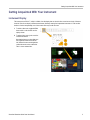
Getting Acquainted With Your Instrument . . ...... . . ...... . ...... ........ ....... ...... . . ...... . ...... ........ ....... ...... . . ...... . .. 11
Instrument Display .............................................................................................................. 11
Front-Panel Controls ... . ...... ........ ...... . ...... ...... . . ...... ....... ...... . . ...... ...... . ...... ........ ...... . ...... ...... . . 14
Rear-Panel Controls ...... . ...... . . ...... ...... . ...... ....... . ...... . ...... ...... . . ...... ...... . ...... . . ...... ...... . ...... ..... 16
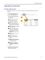
Operating Your Instrument ........................................................................................................... 23
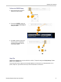
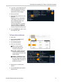
Selecting a Measurement....................................................................................................... 23
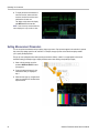
Setting Measurement Parameters.............................................................................................. 24
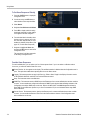
Selecting A mong Inputs.... ........ . ...... . . ...... . ........ ....... ........ ....... . . ...... . ...... . . ....... ........ ....... ........ 26
Dual Link Input Monitoring ..... . ...... . ...... . . ...... . ...... . . ...... . ...... . . ...... . ...... ........ ....... ........ ....... ........ 26
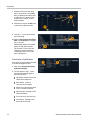
Simultaneous Input Monitoring . . ...... . . ...... . ...... . . ...... . ...... . . ...... . ...... . . ....... ........ ....... ........ ....... ..... 29
Measuring Audio/Video Delay ........ ....... ........ . ...... . . ...... . ........ ....... ........ . ...... . . ...... . ...... . . ....... ..... 31
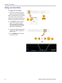
Setting Gain and/or Sweep ...... ........ . ........ ....... . . ....... . . ....... ........ . ........ ....... . . ....... . . ....... ........ . .. 32
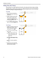
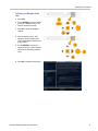
Using Presets ................................................................................................................... 33
Measuring Wa
veforms with Cursors ........................................................................................... 33
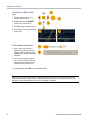
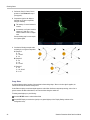
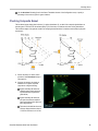
Freezing the Display ............................................................................................................ 35
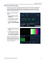
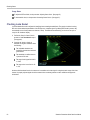
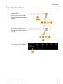
Setting Line Select Mode ....................................................................................................... 38
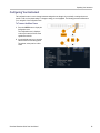
Configuring Your Instrument.................................................................................................... 39
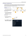
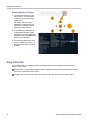
Using Online Help............................................................................................................... 40
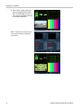
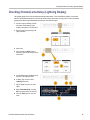
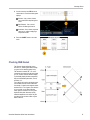
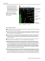
Checking Chroma/Luma Delay (Lightning Display) ................................................................................. 43
Checking Gamut...................................................................................................................... 45
Setup for Gamut Checks........................................................................................................ 46
Checking RGB Gamut .......................................................................................................... 47
Checking Composite Gamut.................................................................................................... 49
Checking Luma Gamut ......................................................................................................... 50
Automating Gamut Checks ..................................................................................................... 51
Adjusting Gamut Limits ......................................................................................................... 53
Waveform Rasterizers Quick Start User Manual i

Table of Content
s
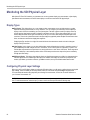
Monitoring the SDI Physical Layer...................................................................................................54
Display Types ................................................................................................................... 5
4
Configuring Physical Layer Settings............................................................................................ 54
Taking Eye Measurements...................................................................................................... 61
Taking Jitter M
easurements .................................................................................................... 66
Taking Cable Loss Measurements ............................................................................................. 70
Using the ARIB Displays ............................................................................................................. 72
ARIB Status ..................................................................................................................... 74
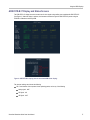
ARIB STD-B.39 Display......................................................................................................... 75
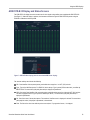
ARIB STD-B.37 Display and Status Screens ........ . . ....... ........ ....... . . ...... . ........ ....... . . ...... . ........ ....... . . 77
ARIB STD-B.35 Di
splay and Status Screens ..... . . ....... ........ ....... ........ ....... ........ ....... ........ ....... ........ 79
ARIB TR-B.23 (1) Display and Status Screens ... ........ ....... ...... . . ...... . ...... . . ...... . ...... . . ...... . ...... . . ...... ... 80
ARIB TR-B.23 (2) Display and Status Screens ... ........ ....... ...... . . ...... . ...... . . ...... . ...... . . ...... . ...... . . ...... ... 81
ARIB TR-B.22 Dis
play and Status Screens.................................................................................... 83
Monitoring Audio.... . ...... . . ...... . ...... ........ ...... . ...... . . ...... . ...... ........ ....... ...... . . ...... . ...... ........ ...... ...... 85
Configuring Audio Inputs..... . ...... . . ...... . ...... . . ...... . ...... . ....... ....... ........ ....... ........ ....... ...... . . ...... . .. 85
Selecting Audio
Input ...... ........ . ...... . . ....... ........ . ...... . . ....... ........ ....... . . ....... ........ ....... . . ...... . ..... 87
Checking Audio Level & Phase.... . ...... . . ...... . ...... ........ ....... ........ ....... ........ ...... . ...... . . ...... . ...... . . ... 88
Checking Surround Sound... ....... ........ . ........ ....... ........ . ...... . . ....... ........ . ...... . . ....... ........ . ...... . . ... 91
Monitor Dolby-Ba
sed Surround Sound .. . . ....... . . ....... . . ....... . . ....... .. ....... .. ......... ......... ......... ......... . ........ 94
Configuring Dolby Inputs...... . . ....... ........ ....... . . ....... ........ ....... . . ...... . ........ ....... . . ...... . ........ ....... . . 94
Displaying Dolby Inputs ... . ........ ....... ........ ....... ........ ....... ........ ....... ........ ....... ........ . ...... . . ...... . 100
Viewing Dolby Met
adata ... . . ...... . ........ ....... . . ....... ........ . ........ ....... . . ....... ........ . ...... .. ....... ........ . 101
Usage Notes................................................................................................................... 102
Monitoring Closed Captioning (CC), Teletext, and Safe Area Compliance ...................................................... 106
Monitoring Close
d Captioning and Teletext .................................................................................. 107
Monitoring for Safe Area Compliance ........................................................................................ 110
Using Alarms........................................................................................................................ 113
Configuring Alarm
s............................................................................................................ 113
Monitoring Alarms............................................................................................................. 117
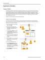
Application Example................................................................................................................ 118
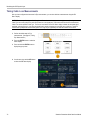
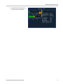
Timing a Studio................................................................................................................ 118
Index
ii Waveform Rasterizers Quick Start User Manual

General Safety S
ummary
General Safet
y Summary
Review the following safety precautions to avoid injury and prevent damage to this product or any products connected to it.
To avoid potential hazards, use this product only as specified.
Only qualified personnel should perform service procedures.
While using this product, you may need to access other parts of a larger system. Read the safety sections of the other
component manuals for warnings and cautions related to operating the system.
To Avoid Fire or Personal Injury
Use Proper Power Cord. Use only the power cord specified for this product and certified for the country of use.
Connect and Disconnect Properly. Connect the probe output to the measurement instrument before connecting the
probe to the ci
rcuit under test. Connect the probe reference lead to the circuit under test before connecting the probe
input. D isconnect the probe input and the probe reference lead from the circuit under test before disconnecting the probe
from the m easurement instrument.
Ground the Product. This product is grounded through the grounding conductor of the power cord. To avoid electric
shock, the gr
ounding conductor must be connected to earth ground. Before making connections to the input or output
terminals of the product, ensure that the product is properly grounded.
Observe All Terminal Ratings. To avoid fire or shock hazard, observe all ratings and markings on the product. Consult
the product manual for further ratings information before making connections to the product.
Do not apply a potential to any terminal, including the common terminal, that exceeds the maximum rating of that terminal.
Power Disconnect. The power cord disconnects the p roduct from the power source. Do not block the power cord; it
must remain
accessible to the user at all times.
Do Not Opera
te Without Covers.
Do not operate this product with covers or panels removed.
Do Not Opera
te With Suspected Failures.
If you suspect that there is damage to this product, have it inspected by
qualified service personnel.
Avoid Exposed Circuitry. Do not touch e xposed connections and components when power is present.
Use Proper Fuse. Use only the fuse type and rating specified for this product.
Do Not Operate in Wet/Damp Conditions.
Do Not Operate in an Explosive Atmosphere.
Keep Product Surfaces Clean and Dry.
Provide P roper Ventilation.
Refer to the manual’s installation instructions for details on installing the product so it has
proper ventilation.
Waveform Rasterizers Quick Start User Manual iii

General Safety S
ummary
TermsinthisManual
These terms may appear in this manual:
WARNING. Warning statements identify conditions or practi ces that could result in injury or loss of life.
CAUTION. Caution statements identify conditions or practices that could r esult in damage to this product or other property.
Symbols and Terms on the Product
These terms may appear on the product:
DANGER indicates an injury hazard immediately accessible as you read the marking.
WARNING indicates a n injury hazard not immediately accessible as you read the marking.
CAUTION indicates a hazard to property including the product.
The following symbol(s) may appear on the product:
iv Waveform Rasterizers Quick Start User Manual

Environmental C
onsiderations
Environmenta
l Considerations
This section provides information about the environmental impact of the product.
Product End-of-Life Han dling
Observe the following guidelines when recycling an instrument or component:
Equipment Recycling. Production of this equipment required the extraction and use of natural resources. The
equipment may contain substances that could be harmful to the environment or human health if improperly handled at the
product’s end of life. In order to avoid release of such substances into the environment and to reduce the use of natural
resources, we encourage you to recycle this product in an appropriate system that will ensure that most of the materials are
reused or recycled appropriately.
The symbol shown below indicates that this product complies with the European Union’s requirements according to Directive
2002/96/EC o n waste electrical and electronic equipment (WEEE). For information about recycling options, check the
Support/Service section of the Tektronix Web site (www.tektronix.com).
Perchlorate Materials. This product contains one or more type “CR” lithium coin cell batteries. According to the
state of California, CR lithium coin cells are classified as perchlorate materials and require special handling. See
www.dtsc.
ca.gov/hazardouswaste/perchlorate for additional information.
Restriction of Hazardous Substances
This product has been classified as Monitoring and Control equipment, and is outside the scope of the 2002/95/EC RoHS
Directive.
Waveform Rasterizers Quick Start User Manual v

Environmental C
onsiderations
Certifications and Compliances
EC Declaration of Conformity – EMC
Meets intent of Directive 2004/108/EC for Electromagnetic Compatibility. Compliance w as demonstrated to the following
specification
saslistedintheOfficial Journal of the European Communities:
EN 55103:1996. Product family standard for audio, video, audio-visual and entertainment lighting c ontrol apparatus for
professional use.
12
Environment E2 – commercial and light industrial
Part 1 Emission
EN 55022:2006. Class B radiated and conducted emissions
EN 55103-1:1996 Annex A. Radiated magnetic field emissions
Part 2 Immunity
IEC 61000-4-2:1999. Electrostatic discharge immunity
IEC 61000-4-3:2002. RF electromagnetic field immunity
IEC 61000-4-4:2004. Electrical fast transient / burst immunity
IEC 61000-4-5:2005. Power line surge immunity
IEC 61000-4-6:2003. Conducted RF Immunity
IEC 61000-4-11:2004. Voltage dips and interruptions immunity
EN 55103-2:1996 Annex A Radiated magnetic field immunity
EN 55103-2:1996 Annex B Balanced ports common mode immunity
EN 61000-3-2:2000. AC power line harmonic emissions
EN 61000-3-3:1995. Voltage changes, fluctuations, and flicker
European Contact.
Tektronix UK, Ltd.
Western Penin
sula
Western Road
Bracknell, RG12 1RF
United Kingdo
m
1
To ensure compliance with the EMC standards listed here, high quality shielded interface cables should be used.
2
Inrush current: 8 A peak.
Australia / Ne
w Z ealand Declaration of Conformity – EMC
Complies with the EMC provision of the Radiocommunications Act per the following standard, in accordance with ACMA:
EN 55103-1:1996. Product family standard for audio, video, audio-visual and entertainment lighting control apparatus
for professional use, Part 1 — emissions.
vi Waveform Rasterizers Quick Start User Manual

Environmental C
onsiderations
EC Declaration of Conformity – Low Voltage
Compliance was demonstrated to the following specification as listed in the Official Journal of the European Communities:
Low Voltage Directive2006/96/EC.
EN 61010-1: 2001. Safety requirements for electrical equipment for measurem ent control and laboratory use.
U.S. Nationally R ecognized Testing Laboratory Listing
UL 61010B-1: 2004, 2
nd
Edition. Standard for electrical measuring and test equipment.
Canadian Cert
ification
CAN/CSA C22.2 No. 61010-1:2004. Safety requirements for electrical equipment for m easurement, control, and
laboratory use. Part 1.
Additional Compliances
IEC 61010-1: 2001. Safety requirements for electrical equipment for m easurem ent, control, and laboratory use.
ISA S82.02.01:1999. Safety s tandard for electrical and electronic test, measuring, controlling, and related equipment.
Equipment Type
Test and measuring equipment.
Safety Class
Class 1 – grounded product.
Pollution
Degree Description
A measure of the contaminants that could occur in the environment around and within a product. Typically the internal
environment inside a product is considered to be the same as the external. Products should be used only in the environment
for which they are rated.
Pollution Degree 1. No pollution or only dry, nonconductive pollution occurs. Products in this category are generally
encapsulated, hermetically sealed, or located in clean rooms.
Pollution Degree 2. Normally only d ry, nonconductive pollution occurs. Occasionally a t emporary conductivity that is
caused by condensation must be expected. This location is a typical office/home environment. Temporary condensation
occurs only when the product is out of service.
Pollution Degree 3. Conductive pollution, or dry, nonconductive pollution that becomes conductive due to condensation.
These are sheltered l ocations where neither temperature nor humidity is controlled. The area is p rotected from direct
sunshine, rain, or direct wind.
Pollution Degree 4. Pollution that generates persistent conductivity through conductive dust, rain, or snow. Typical
outdoor locations.
Waveform Rasterizers Quick Start User Manual vii

Environmental C
onsiderations
Pollution Degree
Pollution Degree 2 (as defined in IEC 61010-1). N ote: Rated for indoor use only.
viii Waveform Rasterizers Quick Start User Manual

Preface
Preface
This manual describes the installation and bas ic operation of the following instruments:
WVR6020
WVR7020
WVR7120
WVR6100 with Option MB
WVR7000 with Option MB
WVR7100 with Option MB
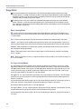
Key Features
Tektronix waveform rasterizers can help you monitor and measure SD SDI, HD SDI, and/or composite analog signals. All
instrument models come standard with SD SDI input monitoring capabilities. The following table includes key features
availableons
tandard equipped instruments. If a feature requires a specific option, the required option is noted.
Feature Description
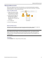
FlexVu™ display
The FlexVu™ display is a four-tiled, high-resolution XGA display that provides four
concurrent v
iews of a monitored signal. The instrument also provides the flexibility to
configure each of the four display tiles independently, enabling you to quickly check
the integrity of a signal. For instruments with the simultaneous input monitoring
(Option SIM
) capability, the F lexVu™ display allows for the monitoring of two signals
at the same time, dividing the display into two sides: one for each signal.
Presets
Customizable presets allow you to quickly save and recall commonly used
configurations.
Digital and analog support
Support for digital applications. Analog support is available with optional
composite
-analog monitoring (Option C PS).
Fully digital processing
Fully Digi
tal Processing allows for accurate, repeatable, drift-free operation that
surpasses traditional analog designs.
Waveform display Traditional waveform disp lays allow signals to be overlaid or paraded.
Vector dis
play
Vector display with Composite and Component Compass Rose Graticules, as
well as gain, sweep, and magnification controls. Traditional and Lightning Vector
displays
are available. The latter visualizes both luma and chroma amplitudes,
as well as quantify inter-channel timing.
Gamut m onitoring Arrowhead, Diamond, and Split Diamond displays offer user-selectable gamut
thresholds so that you can set monitoring limits appropriate to a specific operation.
Gamut mo
nitoring is fully integrated with the ala rm logging and reporting capabilities.
Timing a
nd LTC waveform displays
Longitu
dinal Time Code (LTC) is monitored in a frame rate display to allow
observation of amplitude, synchronization and phase with respect to reference
vertical interval time code (VITC).
Waveform Rasterizers Quick Start User Manual ix

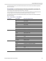
Preface
Feature Description
Surround Sound display of audio signals and phase relationships of normal channel
pairs.
Lissajous disp
lay lets y ou monitor a user-specified pairing of channel inputs.
Support and op
tions for viewing and monitoring both levels of normal channel pairs
for AES, analog, embedded audio, and Dolby signals (Dolby support available with
the WVR6020 and WVR7120, only).
Audio monitoring
Loudness measurement, audio control packet coding, and many popular audio
scales, including BBC scales, are also supported.
Ancillary data monitoring
Support for monitoring ancillary data including data conforming to ARIB standards
and EIA 608 Ex
tended Data Services (XDS).
Closed Capti
oning support
Support for d
ecode and display of CC standards (EIA 608 (VBI), EIA 608 (ANC),
EIA (608/708), EIA 708, TeletextB (VBI), TeletextB OP47 SDP ( ANC), and TeletexB
OP47 Multi (ANC)) with caption text and V-chip information overlaid on the picture
(monitor mo
de) or on Status, Alarm, or E rror screens. There are also settings for
missing (incorrectly inserted) closed captioning.
Picture are
a
Support for standard and custom Safe Graticules for Picture displays for monitoring
for incorrect placements of graphics, logos. Two Safe Area graticules and Safe
Title grat
icules are supported.
Status scr
eens
Status scr
eens provide content status at a glance.
Physical measurements
(Option EY
E and PHY only) Verification and automatic measurement of the electrical
characteristics of the SDI physical layer. An Eye display lets you use the graticule or
voltage and time cursors to measure the waveform. A Jitter waveform display shows
jitter an
d jitter thermometers provide two independent measurements of jitter and
one of cable loss, and relates those measurements to defined alarm limits.
Error tra
cking
Configurable alarms and error logging.
Remote co
ntrol
Full remote control for complete installation flexibility.
x Waveform Rasterizers Quick Start User Manual

Preface
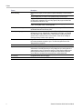
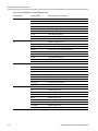
Instrument Options
The W VR6020, WVR7020, and WVR7120 ship with support for monitoring standard definition (SD) serial digital signals. The
following options are available for purchase with the indicated instrument models. You c an verify which options are installed
on your instrument after power-up by pressing the CONFIG button and looking under the View HW/SW Option s submenu.
(See page 7, Connecting Power and Powering On/Off.)
Option
Instrument Description
DL WVR7020
WVR7120
Adds dual link (DL) support. DL allows for the monitoring of
dual link signals. Information from each input is combined and
shown on a single display. Supports all 10 bit and 12 bit YCbCr
and RGB formats. This option includes option H D.
SIM
WVR7120
Adds simultaneous input monitoring (SIM) support. SIM allows
for monitoring of two different input channels at the same time.
Input information is displayed as separate waveform displays in
two FlexVuTM tiles (either horizontally or vertically). Supports
SDI-SDI and SDI-Composite input combinations.
HD WVR7020
WVR7120
Adds support for high definition (HD) serial digital monitoring;
two HD-SDI inputs. This option included with Option DL.
CPS
WVR6020
WVR7020
WVR7120
Adds support for composite (CPS) analog video monitoring
(NTSC and PAL); two passive loop-through inputs; two
composite analog inputs.
AD WVR6020
WVR7020
WVR7120
Adds support for digital audio monitoring, and analog audio
and digital audio in embedded and AES/EBU formats; two sets
of six channels of analog audio inputs; eight channels analog
audio outputs.
DDE WVR7120
Adds option AD c apabilities, plus support for decoding and
monitoring Dolby Digital (AC-3) and Dolby E audio.
AVD WVR7120
Adds support for Audio/Video delay (AVD) measurement.
EYE WVR7120
Adds support for Eye pattern display, jitter m easurements, and
cable parameter measurements.
PHY WVR7120
Adds option EYE capabilities, plus support for jitter waveform
and automated eye measurements.
You can add any or all of the following service options to any instrument:
Option C3. Adds 3 years of Calibration Service.
Option C5. Adds 5 years of Calibration Service.
Option D1. Adds a Calibration Data Report.
Option D3. Adds 3 years of Calibration Data Report (when ordered with option C3).
Option D5. Adds 5 years of Calibration Data Report (when ordered with option C5).
Option R3. A dds 3 years of Repair Service (including the period under warranty).
Option R5. Adds 5 years of Repair Service (including period under warranty).
Waveform Rasterizers Quick Start User Manual xi

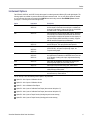
Preface
Where to Find More Information
Item Purpose Location
Quick Start User Manual
(this manual)
Installation
and
high-level overview
of instrument operation
Technical Reference In-depth descriptions of
instrument operation
Online Help
In-depth ins
trument
operation and UI help
Specifications and
Performance Verification
Technical Re
ference
Specifications and
procedure for checking
instrument p
erformance
WVR, WFM, & AMM
Series Management
Information Base (MIB)
Reference
SNMP co mm and
reference for remotely
controlling the
instrument
Service Manual Optional manual
supporting module-level
servicing of the
instrument
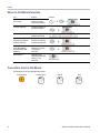
Conventions Used in this Manual
The following icons are used throughout this manual.
Sequence Step Connect power
Network
XGA
xii Waveform Rasterizers Quick Start User Manual

Installation
Installation
Before Installation
Unpack the instrument and check that you have received a ll of the items listed as standard accessories. You may want to
save the shipping carton and packing materials (including the anti-static bag) in case you need to ship the instrument.
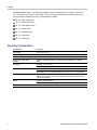
Accessories
The table bel
ow shows which items are standard accessories and which items are optional accessories. Check the Tektronix
Web site (www.tektronix.com) for the most current information on accessories.
Accessory Standard Optional
Tektronix pa
rt
number
WVR6020, WVR7020, and WVR7120 Waveform Rasterizers Quick
Start User Manual
●
071-2231-XX
WVR6020, WVR7020, and WVR7120 Waveform Rasterizers
Release Not
es
●
061-4341-XX
WVR6020, WV
R7020, and WVR7120 Waveform Rasterizers
Customer Documentation CD
This CD contains the following documents in PDF format. (All
documents
are in English unless noted otherwise):
Quick Start User Manual (English, Japanese, Chinese)
Technical Reference
Specificati
ons and Performance Verification Technical Reference
Release Notes
●
063-4056-XX
Power Plug
NOTE. See the International Power Plugs list that follows this table
for the type of power plug included with your instrument.
●
Not applica
ble
Analog/Audio Breakout Cable Assembly
●
012-1688-00
Waveform Rasterizers Quick Start User Manual 1

Installation
International Power Plugs. Your instrument was shipped with one of the following power cord options. Power cords for
use in North Ame
rica are UL listed and CSA certified. Cords for use in areas other than North America are approved by at
least one authority acceptable in the country to which the product i s shipped.
Opt. A0 – North America power
Opt. A1 – Universal EUR power
Opt. A2 – United Kingdom power
Opt. A3 – Australia power
Opt. A5 – Switzerland power
Opt. A6 – Japan power
Opt. A10 – China power
Operating Considerations
Characteristic
Description
Input voltage
100 V to 240 V ±10%
Input power frequency
50 Hz to 60 Hz
Power consumption 100 W maximum, 50 W typical
Analog Audio Output power
capability
Capable of continuously driving a -10 dBFS sine wave into 600 Ω or -13 dB into
300 Ω.
Operating: +0 °C to +50 °C
Temperature
Nonoperating: -40 °C to +75 °C
Operating: 20% to 80% relative humidity (% R H) at up to +40 °C, non-condensing
Humidity
Nonoperating: 5% to 90% relative humidity (% RH) at up to +60 °C, non-condensing
Ventilation
The intake air vents in the front of the instrument must not be blocked and the rear
exhaust ve
nts requires at least 1 inch of clearance. No clearance is required above
or below the instrument.
Operating: 3,000 m (9,842 ft.)
Altitude
Nonoperating: 12,192 m (40,000 ft.)
Pollution
Degree
2, Indoor u
se only
2 Waveform Rasterizers Quick Start User Manual

Installation
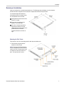
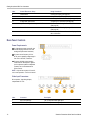
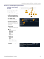
Rackmount Installation
Install your instrument into a standard instrumentation rack. The following procedure will help you do this for both the
standard instrument configuration and for instruments configured with the remote front panel option.
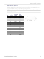
Your instrument ships with hardware for
rackmounting and fits in a standard 19-inch
rack. Requirements of the rack follow:
Spacing between the front rails must be
at least 17-¾ inches.
Front-to-rear rail spacing must be
between 15-½ and 28 inches.
Six inches of clearance between the
instrument rear panel and any rear
cabinet panel for connector space and to
provide adequate air circulation.
Instrument dimensions are shown at
right.
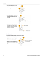
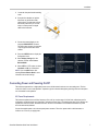
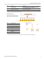
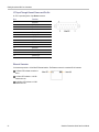
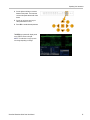
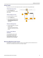
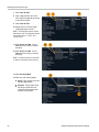
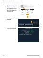
Mounting the Slide Tracks
This procedure covers rear rail mounting details for both deep and shallow racks.
1. Mount the rails using the enclosed
hardware as shown at right.
NOTE. Right hand and left hand stationary
section is designated by the R H and the LH
marked on the rails. Stop latch holes should
be towards the bottom w hen slides are in
place. (The right hand rail is shown.)
Waveform Rasterizers Quick Start User Manual 3

Installation
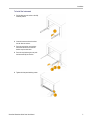
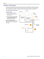
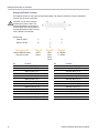
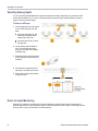
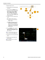
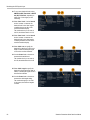
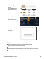
2. Screw-mount to the front rail as shown.
3. Install bar nut if the front rail mounting
hole is not tapped.
4. For a deep configuration, rear mount as
shown. Make sure that the stationary
sections are horizontally aligned, level,
and parallel.
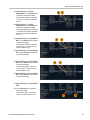
5. Alternately, for a shallow configuration,
rear moun
t as shown. Make sure that
the stationary sections are horizontally
aligned, level, and parallel.
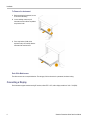
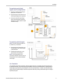
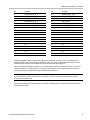
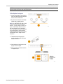
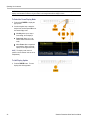
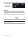
Rack Adjustments
If, aft
er installation, the slide tracks bind, adjust the tracks as follows.
1. Slide the instrument out about 10 inches,
slightly loosen the screws holding the
tracks
to the front rails, and allow the
tracks to seek an unbound position.
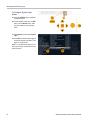
2. Retighten the screws and check the
tracks for smooth operation by sliding the
instr
ument in and out of the rack several
times.
4 Waveform Rasterizers Quick Start User Manual
Page is loading ...
Page is loading ...
Page is loading ...
Page is loading ...
Page is loading ...
Page is loading ...
Page is loading ...
Page is loading ...
Page is loading ...
Page is loading ...
Page is loading ...
Page is loading ...
Page is loading ...
Page is loading ...
Page is loading ...
Page is loading ...
Page is loading ...
Page is loading ...
Page is loading ...
Page is loading ...
Page is loading ...
Page is loading ...
Page is loading ...
Page is loading ...
Page is loading ...
Page is loading ...
Page is loading ...
Page is loading ...
Page is loading ...
Page is loading ...
Page is loading ...
Page is loading ...
Page is loading ...
Page is loading ...
Page is loading ...
Page is loading ...
Page is loading ...
Page is loading ...
Page is loading ...
Page is loading ...
Page is loading ...
Page is loading ...
Page is loading ...
Page is loading ...
Page is loading ...
Page is loading ...
Page is loading ...
Page is loading ...
Page is loading ...
Page is loading ...
Page is loading ...
Page is loading ...
Page is loading ...
Page is loading ...
Page is loading ...
Page is loading ...
Page is loading ...
Page is loading ...
Page is loading ...
Page is loading ...
Page is loading ...
Page is loading ...
Page is loading ...
Page is loading ...
Page is loading ...
Page is loading ...
Page is loading ...
Page is loading ...
Page is loading ...
Page is loading ...
Page is loading ...
Page is loading ...
Page is loading ...
Page is loading ...
Page is loading ...
Page is loading ...
Page is loading ...
Page is loading ...
Page is loading ...
Page is loading ...
Page is loading ...
Page is loading ...
Page is loading ...
Page is loading ...
Page is loading ...
Page is loading ...
Page is loading ...
Page is loading ...
Page is loading ...
Page is loading ...
Page is loading ...
Page is loading ...
Page is loading ...
Page is loading ...
Page is loading ...
Page is loading ...
Page is loading ...
Page is loading ...
Page is loading ...
Page is loading ...
Page is loading ...
Page is loading ...
Page is loading ...
Page is loading ...
Page is loading ...
Page is loading ...
Page is loading ...
Page is loading ...
Page is loading ...
Page is loading ...
Page is loading ...
Page is loading ...
Page is loading ...
Page is loading ...
Page is loading ...
Page is loading ...
Page is loading ...
Page is loading ...
Page is loading ...
Page is loading ...
Page is loading ...
Page is loading ...
Page is loading ...
Page is loading ...
-
 1
1
-
 2
2
-
 3
3
-
 4
4
-
 5
5
-
 6
6
-
 7
7
-
 8
8
-
 9
9
-
 10
10
-
 11
11
-
 12
12
-
 13
13
-
 14
14
-
 15
15
-
 16
16
-
 17
17
-
 18
18
-
 19
19
-
 20
20
-
 21
21
-
 22
22
-
 23
23
-
 24
24
-
 25
25
-
 26
26
-
 27
27
-
 28
28
-
 29
29
-
 30
30
-
 31
31
-
 32
32
-
 33
33
-
 34
34
-
 35
35
-
 36
36
-
 37
37
-
 38
38
-
 39
39
-
 40
40
-
 41
41
-
 42
42
-
 43
43
-
 44
44
-
 45
45
-
 46
46
-
 47
47
-
 48
48
-
 49
49
-
 50
50
-
 51
51
-
 52
52
-
 53
53
-
 54
54
-
 55
55
-
 56
56
-
 57
57
-
 58
58
-
 59
59
-
 60
60
-
 61
61
-
 62
62
-
 63
63
-
 64
64
-
 65
65
-
 66
66
-
 67
67
-
 68
68
-
 69
69
-
 70
70
-
 71
71
-
 72
72
-
 73
73
-
 74
74
-
 75
75
-
 76
76
-
 77
77
-
 78
78
-
 79
79
-
 80
80
-
 81
81
-
 82
82
-
 83
83
-
 84
84
-
 85
85
-
 86
86
-
 87
87
-
 88
88
-
 89
89
-
 90
90
-
 91
91
-
 92
92
-
 93
93
-
 94
94
-
 95
95
-
 96
96
-
 97
97
-
 98
98
-
 99
99
-
 100
100
-
 101
101
-
 102
102
-
 103
103
-
 104
104
-
 105
105
-
 106
106
-
 107
107
-
 108
108
-
 109
109
-
 110
110
-
 111
111
-
 112
112
-
 113
113
-
 114
114
-
 115
115
-
 116
116
-
 117
117
-
 118
118
-
 119
119
-
 120
120
-
 121
121
-
 122
122
-
 123
123
-
 124
124
-
 125
125
-
 126
126
-
 127
127
-
 128
128
-
 129
129
-
 130
130
-
 131
131
-
 132
132
-
 133
133
-
 134
134
-
 135
135
-
 136
136
-
 137
137
-
 138
138
-
 139
139
-
 140
140
-
 141
141
-
 142
142
-
 143
143
-
 144
144


Tektronix WVR6020 Quick start guide
- Category
- Supplementary music equipment
- Type
- Quick start guide
- This manual is also suitable for
Ask a question and I''ll find the answer in the document
Finding information in a document is now easier with AI
Related papers
-
Tektronix WVR611A User manual
-
-
-
-
-
artisan AMM768 User manual
-
-
-
-
Other documents
-
Sony SCD-1 Installation guide
-
Traceable 5017 Owner's manual
-
NEC DTZ-8R-1 Quick start guide
-
NEO Bridge X_NEO User manual
-
evertz 7736CE2 User manual
-
Audient ASP510 User guide
-
-
Hamlet Monitor Scope MS601AX Owner's manual
-
SRS Labs CSD-07D User manual
-
 Dolby Laboratories DP563 User manual
