5
This product requires a three-prong grounded outlet. The installer must perform a
ground continuity check on the power outlet box before beginning the installation to
ensure that the outlet box is properly grounded. If not properly grounded, or if the
outlet box does not meet electrical requirements noted, a qualified electrician should
be employed to correct any deficiencies.
For personal safety, remove house fuse or open circuit breaker before beginning
installation to avoid severe or fatal shock injury. Figure 1
For personal safety, the mounting surface must be capable of supporting the cabinet
load, in addition to the added weight of this 63–85 pound (28.5–38.5 kg) product,
plus additional oven loads of up to 50 pounds (22.7 kg) or a total weight of 113–
135 pounds (51.3–61.2 kg).
For personal safety, this product cannot be installed in cabinet arrangements such as
an island or a peninsula. It must be mounted to BOTH a top cabinet AND a wall.
IMPORTANT – PLEASE READ CAREFULLY. FOR PERSONAL SAFETY, THIS
APPLIANCE MUST BE PROPERLY GROUNDED TO AVOID SEVERE OR FATAL
SHOCK.
The power cord of this appliance is equipped with a three-prong (grounding) plug
which mates with a standard three-prong (grounding) wall receptacle to minimize the
possibility of electric shock hazard from this appliance. Figure 2
You should have the wall receptacle and circuit checked by a qualified electrician to
make sure the receptacle is properly grounded.
Where a standard two-prong wall receptacle is encountered, it is very important to
have it replaced with a properly grounded three-prong wall receptacle, installed by
a qualified electrician.
DO NOT UNDER ANY CIRCUMSTANCES, CUT, DEFORM OR REMOVE ANY OF
THE PRONGS FROM THE POWER CORD. DO NOT USE WITH AN EXTENSION
CORD.
This product requires a three-prong grounded outlet.
The installer must perform a ground continuity check
on the power outlet box before beginning the
installation to ensure that the outlet box is properly
grounded. If not properly grounded, or if the outlet
box does not meet el ectr i cal r equ i r ement s n ot ed
( under EL ECT RI CAL REQUI REMENT S) , a quali fi ed
elect r i ci an shoul d be empl oyed t o cor rect any
defi ci en ci es.
CAUTION: For personal
saf ety, r emove house f use
or open circuit breaker
bef ore beginning
installation to avoid severe
or f atal shock injur y.
CAUTION: For personal safety, the mounting surf ace
must be capable of supporting the cabinet load, in
addition to the added weight of this 63–85 pound
(28.5–38.5 kg) product, plus additional oven loads of
up to 50 pounds (22.7 kg) or a total weight of
113–135 pounds (51.3–61.2 kg).
CAUTION: For personal safety, this product cannot
be installed in cabinet ar rangements such as an island or
a peninsula. It must be mounted to BOTH a top cabinet
AND a wall.
NOTE: For easier installation and personal safety, it is
recommended that two people install this product.
I M PO RTAN T – PL EASE READ CAREFUL LY. FOR
PERSONAL SAFET Y, T H I S APPLI AN CE MU ST BE
PRO PERLY GROUNDED TO AVO I D SEVERE OR
FAT A L SH O CK .
The power cord of this
appliance is equipped with a
three-prong (grounding)
plug which mates with a
standard three-prong
(groundi ng) wall r eceptacle
to minimize the possibility
of electric shock hazard
f rom this appliance.
You should have the wall receptacle and circuit checked
by a qualified electrician to make sure the receptacle is
properly grounded.
Where a st andard two-prong wall r eceptacl e i s
encountered, it i s ver y important to have it replaced
with a pr oper l y gr ounded thr ee-pr ong wall receptacle,
installed by a qualified electrician.
DO NOT, UNDER ANY CI RCUMSTANCES, CUT,
DEFORM OR REMOVE AN Y O F T H E PRO N GS
FROM THE POWER CORD. DO NOT USE WITH
AN EXTENSION CORD.
IMPORTANT SAFETY INSTRUCTIONS
Ensure proper
ground exist s
before use
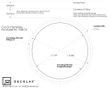
Installat ion Instruct ions
ELECTRICAL
REQUIREM ENTS
Product r ating is 120 volts AC, 60 H ert z, 15 amps and
1.6 kilowatts. This product must be connected to a
The power supply cord and plug should be brought to a
the prevailing local code for this kilowatt rating.
th e r equi r ement s of t he National El ectr ical Code or
vol t age and fr equen cy. Wir e si ze must con for m t o
seperate and dedicated supply circuit of the proper
seper ate and dedi cated 20 amper e br an ch
National Electrical Code or the prevailing local code.
by a qualifed electrician and conform to the
The outler box and supply circuit should be installed
be located in th e cabi n et above the m i cr owave oven.
circuit single grounded outlet. The outlet box should
Figure 2
This product requires a three-prong grounded outlet.
The installer must perform a ground continuity check
on the power outlet box before beginning the
installation to ensure that the outlet box is properly
grounded. If not properly grounded, or if the outlet
box does not m eet el ect r i cal r equi r em ents noted
( under ELECTRI CAL REQU I REMENT S) , a quali fied
elect r i cian sh ould be empl oyed t o corr ect any
def i ci enci es.
CAUTION: For personal
saf ety, r emove house f use
or open circuit breaker
bef ore beginning
installation to avoid severe
or f atal shock injur y.
CAUTION: For personal safety, the mounting surf ace
must be capable of supporting the cabinet load, in
addition to the added weight of this 63–85 pound
(28.5–38.5 kg) product, plus additional oven loads of
up to 50 pounds (22.7 kg) or a total weight of
113–135 pounds (51.3–61.2 kg).
CAUTION: For personal safety, this product cannot
be installed in cabinet arrangements such as an island or
a peninsula. I t must be mounted to BOTH a top cabinet
AND a wall.
NOTE: For easier installation and personal safety, it is
recommended that two people install this product.
I MPO RTAN T – PL EASE READ CAREFULLY. FO R
PERSONAL SAFETY, T H I S APPL I AN CE MU ST BE
PRO PERLY GRO U N DED T O AVO I D SEVERE O R
FAT A L SH O CK .
The power cord of this
appliance is equipped with a
three-prong (grounding)
plug which mates with a
standard three-prong
(groundi ng) wall r eceptacle
to minimize the possibility
of electric shock hazard
f rom this appliance.
You should have the wall receptacle and circuit checked
by a qualified electrician to make sure the receptacle is
properly grounded.
Where a st andar d t wo-prong wall receptacl e i s
encount er ed, it is ver y important to have it replaced
with a proper l y grounded t hr ee-pr ong wall r eceptacle,
installed by a qualified electrician.
DO NO T, U NDER ANY CIRCUMSTANCES, CUT,
DEFORM OR REMO VE AN Y O F T H E PRO N GS
FROM THE POWER CORD. DO NOT USE WITH
AN EXTENSION CORD.
IMPORTANT SAFETY INSTRUCTIONS
Ensure proper
ground exist s
before use
Installation Inst ruct ions
ELECTRICAL
REQUIREM ENTS
Product rati ng i s 120 volts AC, 60 H ertz, 15 amps and
1.6 kilowatts. This product must be connected to a
The power supply cord and plug should be brought to a
the prevailing local code for this kilowatt rating.
th e r equi r ements of th e N ati onal El ectr ical Code or
vol tage and fr equency. Wi r e size must conf or m to
seperate and dedicated supply circuit of the proper
seper ate and dedicated 20 amper e br anch
National Electrical Code or the prevailing local code.
by a qualifed electrician and conform to the
The outler box and supply circuit should be installed
be located i n the cabinet above th e mi cr owave oven.
circuit single grounded outlet. The outlet box should
Figure 1
ELECTRICAL REQUIREMENTS