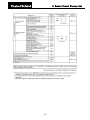
Sanyo SGP-EGW190M Technical Data Manual
- Category
- Split-system air conditioners
- Type
- Technical Data Manual
This manual is also suitable for

TECHNICAL DATA
Gas Heat Pump
Air Conditioner
M2 High Power Excel W Multi
REFERENCE No. TD7110005-00
OUTDOOR MODEL No. PRODUCT CODE No.
SGP-EGW190M2G2W 182680140

High Power Excel W Multi
Contents
System Configuration
・・・・・・・・・・・・・・・・・・・・・・・・・・・・・・・・・・・・・・
A-1
Outdoor Unit
・・・・・・・・・・・・・・・・・・・・・・・・・・・・・・・・・・・・・・・・・・・・・・
B-1
Control
・・・・・・・・・・・・・・・・・・・・・・・・・・・・・・・・・・・・・・・・・・・・・・・・・・・
C-1
Design
・・・・・・・・・・・・・・・・・・・・・・・・・・・・・・・・・・・・・・・・・・・・・・・・・・・
D-1
Installation Work
・・・・・・・・・・・・・・・・・・・・・・・・・・・・・・・・・・・・・・・・・・・
E-1
Separately Sold Parts
・・・・・・・・・・・・・・・・・・・・・・・・・・・・・・・・・・・・・・
F-1
Periodic Inspection
・・・・・・・・・・・・・・・・・・・・・・・・・・・・・・・・・・・・・・・・・
G-1

A-1
System Configuration
Contents
1. Type Configuration
(1) Outdoor unit
・・・・・・・・・・・・・・・・・・・・・・・・・・・・・・・・・・・・・・・・・・・・・・・・・・・・・・・・・・・・・・・
A-2

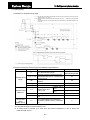
System Configuration
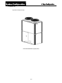
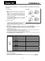
1. Type Configuration
A-2
(1) Outdoor unit
Equivalent horsepower (20)
SGP-EGW190M2G2W (single-phase)

B-1
Outdoor Unit
Contents
1. Gas Usage Conditions
(1) Usable Gas ·····················································································································B-2
(2) Gas Supply Pressure ······································································································B-2
(3) Applicable Gas Type·······································································································B-2
(4) Gas Maximum Flow Volume ···························································································B-2
(5) When using Propane ······································································································B-3
2. Specifications
····················································································································B-4
3. External Dimensions
········································································································B-5
4. Wiring Diagram
·················································································································B-6
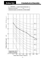
5. Performance Characteristics
··························································································B-7
6. Operating Sound Level Characteristics
(1) Standard Mode ···············································································································B-9
(2) Quiet Mode·····················································································································B-10
7. Vibration Force
(1) Measurement Points ······································································································B-11
(2) Vibration Force···············································································································B-11

Outdoor Unit
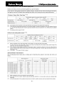
1. Gas Usage Conditions
B-2
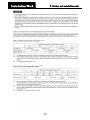
(1) Usable Gas
1) Depending upon the calorific value of the natural gas, the setting for the gas fuel flow rate adjustment
nozzle will differ.
(2) Gas Supply Pressure
Units
:
mbar
Gas Type Maximum Standard Minimum
P 45 37 25
H
,
L
,
E 25 20 17
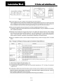
(3) Applicable Gas Type
Group P H L E
Gas composition
Standard gas
Calorific value
(MJ/m
3
N)
C
3
H
8
100%
G31
95.65
CH
4
100%
G20
37.78
CH
4
86% N
2
14%
G25
32.49
CH
4
100%
G20
37.78
Model
Name
190 type
○ ◎ ○ ○
Applicability
◎
:Standard setting when shipped from the factory
○
:Necessary to change the gas type setting on site
(4) Gas Maximum Flow Volume
Gas Maximum flow Volume
(
kW
)
190 type 69
The gas maximum flow volume is the quantity of gas consumed after start up and operating at full
capacity, with the gas at 40°C and at standard pressure.

Outdoor Unit
1. Conditions for gas use
B-3
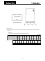
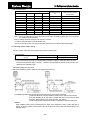
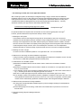
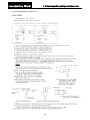
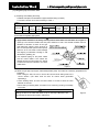
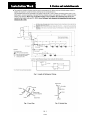
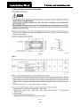
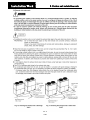
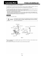
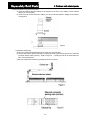
(5) When using Propane
When using Propane as the gas fuel
it is necessary to adjust the fuel adjustment valve and the gas
type setting.
1.Fuel valve setting
With the power supply breaker for the outdoor unit
OFF
1) Move the lever of the P/N switch that is attached to the
mixer part of the engine to the position shown in the
diagram. Turn it 180 degrees in the clockwise direction
(there is a stopper provided). Do not apply unnecessary
force to turn it any further.
2) In the electrical equipment box, fix the "Gas type
setting/Adjustment Completed" label to the prescribed
position for the PL NAME.
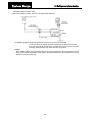
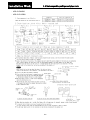
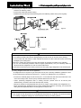
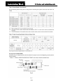
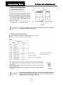
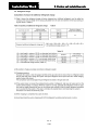
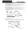
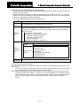
2.Fuel Gas Type Setting
Check that the fuel adjustment valve setting has been
set before operating the outdoor control board.
1)Press the home key (S004) for longer than one second and the menu item number will be displayed.
2)Next, press the up (S005)/down (S006) key to set the menu item number to.
3)After displaying
, is displayed. When is displayed press the set
(S007) key. The green LED (D053) lights up, and the system address setting is displayed.
(For example:
)
4)Next operate the down (S006)/up (S005) key, to display the gas type setting. When the gas type setting is
displayed, press the set (S007) key for longer than one second.
Note: When setting the gas type,
** is displayed.(for ** enter 00-05)
5)A red LED (D052) lights up, indicating that a forced setting is being carried out. In this condition, press the
down (S006)/up (S005) key, and select the gas type.
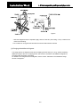
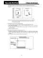
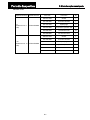
The relationship between display and gas type is as shown in the following table.
Display Gas type
(GAS
00)
Propane G31
(GAS
01) -
(GAS
02)
Natural gas G20
(GAS
03)
Natural gas G25
(GAS
04) -
(GAS
05) -
(GAS
06)
-
(GAS
07)
-
(GAS
08)
-
(GAS
09)
-
(GAS
0A)
-
(GAS
0b)
-
(GAS
0C)
-
(GAS
0d)
-
(GAS
0E)
-
Up key
(S005)
Down key
(S006)
(GAS
0F)
-
* When the H/L/E gas type is selected, the oil replacement time warning is not displayed.
6)After completing selection of gas type, press the set (S007) key for longer than 1 second. The red LED
(D052) will be extinguished.
7)Press the home (S004) key to complete the setting.
Note: When using propane, change the setting in accordance with the above procedure to

Outdoor unit
2. Specifications
B-4
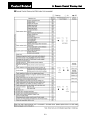
Model No. SGP-EGW190M2G2W
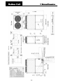
External dimensions (mm)
Height 2,248
Width 1,800
Depth 1,000(+60)
Weight (kg) 875
Performance (kW)
Cooling capacity 56.0
Heating capacity (Standard) 63.0
Heating capacity (low temp.) 67.0
Hot Water (Cooling mode) 22.0 (@75°C exhaust)
Power generation capacity (rating) DC2.5 (Maximum of 4.3)
Generate electricity power source
220 to 240 V, 50 Hz,
Single-phase
Power supply specification
100/200 V, 50 Hz,
Single-phase, 3-wire
Electrical rating
Running amperes (A) 6.18
Power input (kW) 1.35
Cooling
Power factor (%) 95
Running amperes (A) 4.57
Power input (kW) 1.01
Heating
Power factor (%) 96
Starting amperes (A) 30
Gas Type
P Propane gas (G31)
H Natural gas (G20)
L Natural gas (G25)
Gas Band
E Natural gas (G20)
Gas consumption (kW)
Cooling 44.0 <38.3>
Heating (Standard) 48.7 <43.0>
Heating (low temp.) 62.1 <56.4>
Compressor
Cooling oil (L) (type) 7.5 (HP-9)
Crankcase heater (W) 30
Paint color (Munsell code) Silky Shade (1Y8.5/0.5)
Notes
1. Cooling and heating capacities in the tables are determined under the test conditions of JIS B 8627.
Operating condition Cooling Heating (standard) Heating (low temp.) Heating (cold environ.)
Indoor air intake
temp.
27°C DB /19°C WB 20°C DB <
20°C DB/15°C WB < 20°C DB/15°C WB
Outdoor air intake
temp.
35°CDB 7°CDB/6°CWB 2°CDB/1°CWB -10°CDB/-11°CWB
・Effective heating requires that the outdoor air intake temperature be at least –20°CDB or –21°CWB.
2. The Generate electricity is the generating-end output. The power output externally is calculated by subtracting the
self-consumed power. Power generation output is controlled in accordance with the air conditioning load, and the
maximum power that can be generated is 4.3 kW.
3. Gas consumption is the total (high) calorific value standard.
4. Outdoor unit operating sound is measured 1 meter from the front and 1.5 meters above the floor (in an anechoic
environment). In actual installations, values are normally larger than those indicated due to ambient noise and
reflections.
5. Quantities of gas and liquid refrigerant in parentheses ( ) apply when the maximum piping length exceeds 90 meters
(equivalent length). (Reducers are available locally.)
6. Specifications are subject to change without notice.
7. The gas consumption in < > apply when generator is not running.
8. Hot water heating capacity is applicable during cooling operation as in Note 1.
Engine
Displacement (L) 2.488
Rated output (kW) 12.4
Type Sanyo Genuine
Oil
Quantity (L) 46
Starter motor DC12V × 2.2kW
Starter type
AC/DC conversion type DC
starter
Engine cooling water
Quantity (L) 27
Concentration, Freezing
temperature
50 V/V%, –35°C
Cooling water pump rated
output (kW)
0.16
Refrigerant type, Quantity
(kg)
HFC [R410A], 11.5
Air intakes Front and Rear
Air outlet Top
Piping
Refrigerant gas (mm)
φ28.58.(brazed)
(φ31.75.) (Note 5)
Refrigerant liquid (mm)
φ15.88.(brazed)
(φ19.05.) (Note 5)
Balance (mm)
φ9.52.(flared)
Fuel gas R3/4 (Bolt, thread)
Exhaust drain (mm) φ25 . Rubber hose (length: 200)
Hot water supply in/out Rp3/4 (Nut, thread)
Operating sound dB(A) 58
Ventilation System
Type Propeller fans (×2)
Air flow rate (m
3
/min) 380
Rated output (kW) 0.70 × 2
Drain heater (W) 40
Generator
Capacity (kW) 4.3

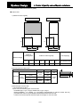
Outdoor Unit
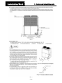
3. External Dimensions
B-5

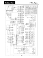
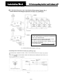
Outdoor Unit
4. Wiring Diagram
B-9

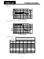
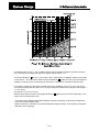
Outdoor unit
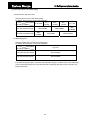
5. Performance Characteristics
B-7
Cooling
Performance
•
Gas consumption (including gas consumption for power generation)
•
Power generation amount (Unit: kW)
Indoor intake air wet bulb temperature °CWB
16°C 18°C 19°C 20°C 22°C 24°C
Outdoor air
temperature
°CDB
Power
generation
amount
Power
generation
amount
Power
generation
amount
Power
generation
amount
Power
generation
amount
Power
generation
amount
25
4.29 4.29 3.26 3.26 2.50 2.50
27
4.29 3.26 3.26 2.50 2.50 2.50
29
4.29 3.26 2.50 2.50 2.50 2.50
31
3.26 3.26 2.50 2.50 2.50 2.50
33
3.26 2.50 2.50 2.50 2.50 2.50
35
3.26 2.50 2.50 2.50 2.50 2.50
37
2.50 2.50 2.50 2.50 2.50 3.26
39
2.50 2.50 2.50 2.50 3.26 3.26
SGP-EGW190M2G2W

Outdoor unit
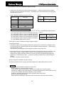
5. Performance Characteristics
B-8
Heating
Performance
•
Gas consumption (including gas consumption for power generation)
•
Power generation amount (Unit: kW)
Indoor intake air dry bulb temperature °CWB
Outdoor air
temperature
16°C 18°C 20°C 22°C 24°C
°CDB °CWB
Power
generation
amount
Power
generation
amount
Power
generation
amount
Power
generation
amount
Power
generation
amount
-7 -7.6
3.26 3.26 2.50 2.50 2.50
-5 -5.6
3.26 2.50 2.50 2.50 2.50
-3 -3.7
3.26 2.50 2.50 2.50 2.50
0 -0.7
2.50 2.50 2.50 2.50 2.50
3 2.2
2.50 2.50 2.50 2.50 2.50
5 4.1
2.50 2.50 2.50 2.50 2.50
7 6
2.50 2.50 2.50 2.50 3.26
9 7.9
2.50 2.50 2.50 3.26 3.26
11 9.8
2.50 2.50 3.26 3.26 3.26
13 11.8
2.50 2.50 3.26 3.26 3.26
SGP-EGW190M2G2W

Outdoor Unit
6. Operating Sound Level Characteristics
B-9
(1) Standard Mode

Outdoor Unit
6. Operating Sound Level Characteristics
B-10
(2) Quiet Mode

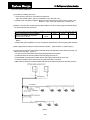
Outdoor Unit
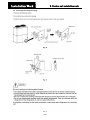
7. Vibration Force
B-11
(1) Measurement Points
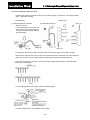
(2) Vibration Force
Maximum vibration force at each frequency is measured over the whole range of engine rotation speeds
and loads.
(1) Type 190
Maximum values while changing rotation rate from 800 to 2200 r/min.
1/3
rd
octave
Frequency (Hz)
3.15 4 5 6.3 8 10 12.5 16 20 25
Vibration force F (N)
1.13 1.66 4.6 5.33 16.8 25.6 39.8 38.4 14.1 15.4
F
Vibration force level 20log
10
F
0
1.06 4.38 13.3 14.5 24.5 28.2 32 31.7 23 23.8
Vibration acceleration (dB)
16.3 27.7 33 36.7 42.5 43.6 45.4 38.4 38.8 41.8
31.5
40 50 63 80 100 125 160 200 250 315
Compound
Value
75.9 143 174 155 127 112 155 359 148 109 92.4 555.8
37.6 43.1 44.8 43.8 42.1 41 43.8 51.1 43.4 40.8 39.3 54.9
37.7 33.4 31.8 30.6 25.2 22.2 19.8 25.7 22.9 32.6 26 51.0
F: Vibration Force (N)
F
0
: 1N

C-1
Control
Contents
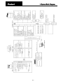
1. System Block Diagram···············································································
C-2
2. Warning Lists
(1) Remote Control Warning List (with Indoor Unit cnnected) ································· C-3

Control
1. System Block Diagram
C-2
C-2

Control-Related
2. Remote Control Warning List
C-3

Control-Related
2. Remote Control Warning List
C-4

Control-Related
2. Remote Control Warning List
C-5
Page is loading ...
Page is loading ...
Page is loading ...
Page is loading ...
Page is loading ...
Page is loading ...
Page is loading ...
Page is loading ...
Page is loading ...
Page is loading ...
Page is loading ...
Page is loading ...
Page is loading ...
Page is loading ...
Page is loading ...
Page is loading ...
Page is loading ...
Page is loading ...
Page is loading ...
Page is loading ...
Page is loading ...
Page is loading ...
Page is loading ...
Page is loading ...
Page is loading ...
Page is loading ...
Page is loading ...
Page is loading ...
Page is loading ...
Page is loading ...
Page is loading ...
Page is loading ...
Page is loading ...
Page is loading ...
Page is loading ...
Page is loading ...
Page is loading ...
Page is loading ...
Page is loading ...
Page is loading ...
Page is loading ...
Page is loading ...
Page is loading ...
Page is loading ...
Page is loading ...
Page is loading ...
Page is loading ...
Page is loading ...
Page is loading ...
Page is loading ...
Page is loading ...
Page is loading ...
Page is loading ...
Page is loading ...
Page is loading ...
Page is loading ...
Page is loading ...
Page is loading ...
Page is loading ...
Page is loading ...
-
 1
1
-
 2
2
-
 3
3
-
 4
4
-
 5
5
-
 6
6
-
 7
7
-
 8
8
-
 9
9
-
 10
10
-
 11
11
-
 12
12
-
 13
13
-
 14
14
-
 15
15
-
 16
16
-
 17
17
-
 18
18
-
 19
19
-
 20
20
-
 21
21
-
 22
22
-
 23
23
-
 24
24
-
 25
25
-
 26
26
-
 27
27
-
 28
28
-
 29
29
-
 30
30
-
 31
31
-
 32
32
-
 33
33
-
 34
34
-
 35
35
-
 36
36
-
 37
37
-
 38
38
-
 39
39
-
 40
40
-
 41
41
-
 42
42
-
 43
43
-
 44
44
-
 45
45
-
 46
46
-
 47
47
-
 48
48
-
 49
49
-
 50
50
-
 51
51
-
 52
52
-
 53
53
-
 54
54
-
 55
55
-
 56
56
-
 57
57
-
 58
58
-
 59
59
-
 60
60
-
 61
61
-
 62
62
-
 63
63
-
 64
64
-
 65
65
-
 66
66
-
 67
67
-
 68
68
-
 69
69
-
 70
70
-
 71
71
-
 72
72
-
 73
73
-
 74
74
-
 75
75
-
 76
76
-
 77
77
-
 78
78
-
 79
79
-
 80
80


Sanyo SGP-EGW190M Technical Data Manual
- Category
- Split-system air conditioners
- Type
- Technical Data Manual
- This manual is also suitable for
Ask a question and I''ll find the answer in the document
Finding information in a document is now easier with AI
Related papers
Other documents
-
Fujitsu AOYG45LBT8 Installation guide
-
Daikin FTXG50JV1BA Datasheet
-
Hitachi RAM-112FPSQB User manual
-
Panasonic U-72MF1U9E User manual
-
Haier 3U55S2SR2FA User manual
-
Impecca ISFW6018X3 User manual
-
Haier MRVII-S AU282FHERA Installation & Maintenance Instructions Manual
-
Mitsubishi PUHY-HP-THMU-A User guide
-
Mitsubishi Electric PURY-HP144 Installation guide
-
Dwyer Series FTS User manual