Chauvet Professional Maverick Force 2 Profile User manual
- Category
- Floodlights
- Type
- User manual

Model ID: MAVERICKFORCE2PROFILE
User Manual

Maverick Force 2 Profile User Manual Rev. 7
Edition Notes
The Maverick Force 2 Profile User Manual includes a description, safety precautions, installation,
programming, operation and maintenance instructions for the Maverick Force 2 Profile as of the release
date of this edition.
Trademarks
Chauvet, Chauvet Professional, the Chauvet logo, and Maverick are registered trademarks or trademarks
of Chauvet & Sons, LLC (d/b/a Chauvet and Chauvet Lighting) in the United States and other countries.
Other company and product names and logos referred to herein may be trademarks of their respective
companies.
Copyright Notice
The works of authorship contained in this manual, including, but not limited to, all designs, text, and images
are owned by Chauvet.
© Copyright 2023 Chauvet & Sons, LLC. All rights reserved.
Electronically published by Chauvet in the United States of America.
Manual Use
Chauvet authorizes its customers to download and print this manual for professional information purposes
only. Chauvet expressly prohibits the usage, copy, storage, distribution, modification, or printing of this
manual or its content for any other purpose without written consent from Chauvet.
Document Printing
For best results, print this document in color, on letter size paper (8.5 x 11 in), double-sided. If using A4
paper (210 x 297 mm), configure the printer to scale the content accordingly.
Intended Audience
Any person installing, operating, and/or maintaining this product should completely read through the guide
that shipped with the product, as well as this manual, before installing, operating, or maintaining this
product.
Disclaimer
Chauvet believes that the information contained in this manual is accurate in all respects. However,
Chauvet assumes no responsibility and specifically disclaims any and all liability to any party for any loss,
damage or disruption caused by any errors or omissions in this document, whether such errors or
omissions result from negligence, accident or any other cause. Chauvet reserves the right to revise the
content of this document without any obligation to notify any person or company of such revision, however,
Chauvet has no obligation to make, and does not commit to make, any such revisions. Download the latest
version from www.chauvetprofessional.com.
Document Revision
This is revision 7 of the Maverick Force 2 Profile User Manual. Go to www.chauvetprofessional.com for the
latest version.
Revision Date Description
7 09/2023 Updated USB section / added revision log

Maverick Force 2 Profile User Manual Rev. 7
Table of Contents
i
TABLE OF CONTENTS
1. Before You Begin ....................................................................... 1
What Is Included.................................................................................. 1
Claims.................................................................................................. 1
Text Conventions................................................................................. 1
Symbols............................................................................................... 1
Safety Notes ........................................................................................ 2
FCC Statement of Compliance............................................................ 3
RF Exposure Warning for North America, and Australia ..................... 3
Expected LED Lifespan ....................................................................... 3
2. Introduction ................................................................................ 4
Description........................................................................................... 4
Features .............................................................................................. 4
Product Overview ................................................................................ 4
Product Dimensions ............................................................................ 5
3. Setup ........................................................................................... 6
AC Power ............................................................................................ 6
AC Plug.................................................................................................... 6
Fuse Replacement................................................................................... 6
Remote Device Management .............................................................. 6
USB Software Update ......................................................................... 7
Mounting.............................................................................................. 8
Orientation ............................................................................................... 8
Rigging..................................................................................................... 8
Procedure ................................................................................................ 8
Signal Connections.............................................................................. 9
Control Personalities................................................................................ 9
DMX Linking ............................................................................................ 9
Art-Net™ Connection............................................................................... 9
sACN Connection .................................................................................... 9
Connection Diagram................................................................................ 9
4. Operation .................................................................................... 10
Touchscreen Control Panel ................................................................. 10
Control Panel Description ........................................................................ 10
Battery Powered Display ......................................................................... 10
Home Screen....................................................................................... 10
Control Panel Lock .............................................................................. 10
Passcode ................................................................................................. 10
Technician Mode ................................................................................. 10
Menu Map............................................................................................ 11
Control Configuration........................................................................... 16
Control Mode ........................................................................................... 16
Control Personalities................................................................................ 16
Starting Address ...................................................................................... 16

Table of Contents
Maverick Force 2 Profile User Manual Rev. 7
ii
Network Setup ......................................................................................... 16
IP Mode ........................................................................................................ 16
Universe ....................................................................................................... 16
Manual IP Address ....................................................................................... 16
Subnet Mask ................................................................................................ 16
Control Channel Assignments and Values .......................................... 17
Settings Configuration ......................................................................... 21
Pan Reverse............................................................................................ 21
Tilt Reverse.............................................................................................. 21
Screen Reverse....................................................................................... 21
Pan Angle ................................................................................................ 21
Tilt Angle.................................................................................................. 21
Blackout on Movement ............................................................................ 21
Touchscreen Calibration.......................................................................... 21
Touchscreen Lock ................................................................................... 21
Swap Pan and Tilt.................................................................................... 21
WDMX Reset........................................................................................... 22
Display Backlight Timer ........................................................................... 22
Loss of Data............................................................................................. 22
Fan Mode................................................................................................. 22
Dimmer Curve.......................................................................................... 22
Pulse Width Modulation ........................................................................... 22
LED Power............................................................................................... 22
Minimum Zoom Focus ............................................................................. 22
Preset Selection....................................................................................... 23
Preset Synchronization............................................................................ 23
USB Update............................................................................................. 23
Reset Function......................................................................................... 23
Factory Reset .......................................................................................... 23
Test Mode............................................................................................ 24
Auto Test ................................................................................................. 24
Manual Test............................................................................................. 24
System Information.............................................................................. 24
Zero Adjust Mode ................................................................................ 24
Web Server.......................................................................................... 25
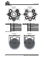
Gobo Wheels....................................................................................... 26
Gobo Dimensions .................................................................................... 26
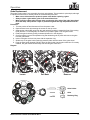
Gobo Replacement.................................................................................. 27
5. Maintenance................................................................................ 28
Product Maintenance........................................................................... 28
6. Technical Specifications ........................................................... 29
Contact Us ...................................................................................... 30
Warranty & Returns ............................................................................. 30

1
Maverick Force 2 Profile User Manual Rev. 7
Before You Begin
1. Before You Begin
What Is Included
Claims
Carefully unpack the product immediately and check the container to make sure all the parts are in the
package and are in good condition.
If the box or the contents (the product and included accessories) appear damaged from shipping, or show
signs of mishandling, notify the carrier immediately, not Chauvet. Failure to report damage to the carrier
immediately may invalidate the claim. In addition, keep the box and contents for inspection.
For other issues, such as missing components or parts, damage not related to shipping, or concealed
damage, file a claim with Chauvet within 7 days of delivery.
Text Conventions
Symbols
• Maverick Force 2 Profile
• Seetronic Powerkon IP65 power cable
• 2 Omega Brackets with mounting hardware
• Quick Reference Guide
Convention Meaning
1–512 A range of values
50/60 A set of values of which only one can be chosen
Settings A menu option not to be modified
<ENTER> A key to be pressed on the product’s control panel
Symbol Meaning
Critical installation, configuration, or operation information. Not following these
instructions may make the product not work, cause damage to the product, or cause
harm to the operator.
Important installation or configuration information. The product may not function correctly
if this information is not used.
Useful information.
The term “DMX” used throughout this manual refers to the USITT DMX512-A digital data
transmission protocol.

2
Before You Begin
Maverick Force 2 Profile User Manual Rev. 7
Safety Notes
Read all the following safety notes before working with this product. These notes contain important
information about the installation, usage, and maintenance of this product.
• The luminaire is intended for professional use only.
• The luminaire should be positioned so that prolonged staring into the luminaire at a distance closer than
25.59 ft (7.8 m) is not expected.
• If the external flexible cable or cord of this luminaire is damaged, it shall be replaced by a special cord
or cord exclusively available from the manufacturer or its service agent.
• The light source contained in this luminaire shall only be replaced by the manufacturer or its service
agent or a similar qualified person.
• CAUTION:
• This product’s housing may be hot when operating. Mount this product in a location with adequate
ventilation, at least 20 in (50 cm) from adjacent surfaces.
• When transferring the product from extreme temperature environments, (e.g., cold truck to warm
humid ballroom) condensation may form on the internal electronics of the product. To avoid causing
a failure, allow the product to fully acclimate to the surrounding environment before connecting it to
power.
• Flashing light is known to trigger epileptic seizures. User must comply with local laws regarding
notification of strobe use.
• ALWAYS:
• Disconnect from power before cleaning the product or replacing the fuse.
• Replace the fuse with the same type and rating.
• Use a safety cable when mounting this product overhead.
• Connect this product to a grounded and protected circuit.
•DO NOT:
• Open this product. It contains no user-serviceable parts.
• Look at the light source when the product is on.
• Leave any flammable material within 50 cm of this product while operating or connected to power.
• Connect this product to a dimmer or rheostat.
• Operate this product if the housing, lenses, or cables appear damaged.
• Operate this product outdoors or in any location where dust, excessive heat, water, or humidity may
affect it (adhere to standards for the published IP rating).
• ONLY use the handles or the hanging/mounting brackets to carry this product.
• The maximum ambient temperature is 113 °F (45 °C). Do not operate this product at higher
temperatures.
• The minimum startup temperature is -4°F (-20°C). Do not start the product at lower temperatures.
• The minimum ambient temperature is -22°F (-30°C). Do not operate the product at lower temperatures.
• To eliminate unnecessary wear and improve its lifespan, during periods of non-use completely
disconnect the product from power via breaker or by unplugging it.
• In the event of a serious operating problem, stop using immediately.
This product contains no user-serviceable parts. Any reference to servicing in this User
Manual will only apply to properly trained, certified technicians. Do not open the housing
or attempt any repairs.
All applicable local codes and regulations apply to proper installation of this product.
If a Chauvet product requires service, contact Chauvet Technical Support.

3
Maverick Force 2 Profile User Manual Rev. 7
Before You Begin
FCC Statement of Compliance
This device complies with Part 15 Part B of the FCC rules. Operation is subject to the following two
conditions:
1. This device may not cause harmful interference, and
2. This device must accept any interference received, including interference that may cause
undesired operation.
This equipment has been tested and found to comply with the limits for a Class B digital device, pursuant
to Part 15 of the FCC Rules. These limits are designed to provide reasonable protection against harmful
interference in a residential installation. This equipment generates uses and can radiate radio frequency
energy and, if not installed and used in accordance with the instructions, may cause harmful interference
to radio communications. However, there is no guarantee that interference will not occur in a particular
installation. If this equipment does cause harmful interference to radio or television reception, which can be
determined by turning the equipment off and on, the user is encouraged to try to correct the interference by
one or more of the following measures:
• Reorient or relocate the receiving antenna.
• Increase the separation between the equipment and receiver.
• Connect the equipment into an outlet on a circuit different from that to which the receiver is
connected.
• Consult the dealer or an experienced radio/TV technician for help.
Any changes or modifications not expressly approved by the party responsible for compliance could void
the user’s authority to operate the equipment.
RF Exposure Warning for North America, and Australia
Warning! This equipment complies with FCC radiation exposure limits set forth for an uncontrolled
environment. This equipment should be installed and operated with a minimum distance of 20cm between
the radiator and the user. This transmitter must not be co-located or operating in conjunction with any other
antenna or transmitter.
Expected LED Lifespan
Over time, use and heat will gradually reduce LED brightness. Clustered LEDs produce more heat than
single LEDs, contributing to shorter lifespans if always used at full intensity. The average LED lifespan is
40,000 to 50,000 hours. To extend LED lifespan, maintain proper ventilation around the product, and limit
the overall intensity.

4
Introduction
Maverick Force 2 Profile User Manual Rev. 7
2. Introduction
Description
The Maverick Force 2 Profile is a lightweight, tour-grade moving head with a big presence. The powerful
product features an output of over 20,000 lumens and an artillery of speedy effects housed in a deceptively
compact frame, under 60lbs. The Maverick Force 2 Profile features CMY + CTO color-mixing, a color
wheel with a CTB and CRI option, and an extensive zoom range of 7 to over 50 degrees that maintains a
flat field of focus even when fully wide. A custom-built framing system containing 4 dual axis shutters with
a 120-degree field of rotation, motorized iris, focus, zoom, and frost capabilities, alongside a 5-facet
rotating prism give an abundance of tools for beam shaping. Two rotating glass gobo wheels featuring
gobos created in collaboration with leading designers can be stacked on top of one another for dynamic
effects. Control as desired with DMX, sACN, Art-Net or W-DMX.
Features
• Fully featured, compact and lightweight 580 W LED yoke profile fixture including CMY + CTO color
mixing, a 4-blade framing shutter system with rotation, a color wheel, 8:1 zoom, a 5-facet prism
wheel, and 2 rotating gobo wheels
• 16-bit dimming of master dimmer for smooth control of fades
• Variable CMY + CTO color mixing system to create a wide pallet of colors
• CRI and CTB filters on color wheel for added flexibility
• Two rotating, indexing and interchangeable slot and lock gobo wheels
• DMX, WDMX, sACN, and Art-Net for full flexibility of control options
• RDM control over DMX for fixture reporting
• 6.8° to 55.9° zoom range for variable beam sizes
• Iris, 5-facet prism and frost for beam control
• True 1 compatible power input
• Three setup menu presets and preset sync for cross loading to multiple like fixtures for easy shop
setup
• USB slot for software uploads
• Battery backup display with auto-rotate depending on fixture orientation
Product Overview
Menu
buttons
LCD
display
DMX
in/out
Power
switch
Carry
handle
Power
in
Fuse
holder
Ethernet
ports
WDMX
antenna
USB A
port

5
Maverick Force 2 Profile User Manual Rev. 7
Introduction
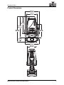
Product Dimensions
26.38 in
670 mm
11.22 in
285 mm
15.11 in
384 mm
21.72 in
552 mm
17.79 in
452 mm
15.51 in
394 mm
10.71 in
272 mm
10.0 in
254 mm
4.51 in
114 mm
13.9 in
353 mm

6
Setup
Maverick Force 2 Profile User Manual Rev. 7
3. Setup
AC Power
The Maverick Force 2 Profile has an auto-ranging power supply and it can work with an input voltage
range of 100 to 240 VAC, 50/60 Hz.
To determine the product’s power requirements (circuit breaker, power outlet, and wiring), use the current
value listed on the label affixed to the product’s back panel, or refer to the product’s specifications chart.
The listed current rating indicates the product’s average current draw under normal conditions.
AC Plug
The Maverick Force 2 Profile comes with a power input cable terminated with a Seetronic Powerkon A
connector on one end and an Edison plug on the other end (U.S. market). If the power input cable that
came with the product has no plug, or if it is necessary to change the plug, use the table below to wire the
new plug.
Fuse Replacement
1. Disconnect this product from the power outlet.
2. Using a flat-head screwdriver, unscrew the fuse holder cap from the housing.
3. Remove the blown fuse and replace with another fuse of the same type and rating (F 20 A, 250 V).
4. Screw the fuse holder cap back in place and reconnect power.
Remote Device Management
Remote Device Management, or RDM, is a standard for allowing DMX-enabled devices to communicate
bi-directionally along existing DMX cabling. Check the DMX controller’s User Manual or with the
manufacturer as not all DMX controllers have this capability. The Maverick Force 2 Profile supports RDM
protocol that allows feedback to make changes to menu map options.
• Always connect the product to a protected circuit (a circuit breaker or fuse). Make sure
the product has an appropriate electrical ground to avoid the risk of electrocution or
fire.
• To eliminate unnecessary wear and improve its lifespan, during periods of non-use
completely disconnect the product from power via breaker or by unplugging it.
Never connect the product to a rheostat (variable resistor) or dimmer circuit, even if the
rheostat or dimmer channel serves only as a 0 to 100% switch.
Connection Wire (U.S.) Wire (Europe) Screw Color
AC Live Black Brown Yellow or Brass
AC Neutral White Blue Silver
AC Ground Green/Yellow Green/Yellow Green

7
Maverick Force 2 Profile User Manual Rev. 7
Setup
USB Software Update
The Maverick Force 2 Profile allows for software updates with a USB device using the built-in USB port. To
update the software using a USB flash drive, do the following:
1. Power on the product, and plug the flash drive into the USB port.
2. Once the flash drive has been detected, the message “
USB UPDATE
” will be displayed. Select
YES
.
3. The next screen will show the software versions available for this fixture on the USB drive. For
multiple versions of the software for the same fixture, use <UP> or <DOWN> to select the desired
version. Press <ENTER>.
4. The “USB UPDATE” screen will re-appear. Select YES.
5. The upgrade will start. DO NOT turn off the power or disconnect the USB while the USB LED is
still blinking during the process. The screen display will read: “USB Update Wait”. The update can
take several minutes to complete.
• When the USB firmware is done uploading, in some fixtures, the display will change to:
“DO NOT UNPLUG, UPDATING”.
6. When the update is completed, the fixture will automatically reboot.
7. Go to Fixture Information on the product’s menu map and confirm the firmware revision.
8. When the boot-up process is finished, restart the product.
It is possible to update multiple units with the USB if they are daisy chained via DMX.
• Place the .chl file in the root directory of the USB drive.
• The product's USB port supports up to 32GB capacity and only works with FAT32 file format.
Turning off the power or removing the USB while the USB LED is still blinking during the
update will cause partial or total firmware failure in the targeted fixture(s). If this occurs, the
user will need the UPLOAD 08 device to fix this. Please contact Chauvet regarding this device.

8
Setup
Maverick Force 2 Profile User Manual Rev. 7
Mounting
Before mounting the product, read and follow the safety recommendations indicated in the Safety Notes.
Orientation
Always mount this product in a safe position, making sure there is adequate room for ventilation,
configuration, and maintenance.
Rigging
Chauvet recommends using the following general guidelines when mounting this product.
• Before deciding on a location, always make sure there is easy access to the product for
maintenance and programming.
• Make sure adequate ventilation is provided around the product.
• Make sure that the structure and attachment points can support the weight before hanging the
product (see theTechnical Specifications).
• When mounting the product overhead, always use a safety cable. Mount the product securely to a
rigging point, whether an elevated platform or a truss.
• When rigging the product onto a truss, use a mounting clamp of appropriate weight capacity.
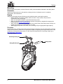
Procedure
The Maverick Force 2 Profile comes with 2 Omega brackets to which the user can directly attach mounting
clamps (sold separately). Make sure the clamps are capable of supporting the weight of this product. Use
at least two mounting points per product. For the Chauvet Professional line of mounting clamps, go to
http://www.trusst.com/products.
Mounting Diagram
Safety Cable
Mounting Clamp (x2)
Omega Bracket (x2)

9
Maverick Force 2 Profile User Manual Rev. 7
Setup
Signal Connections
The Maverick Force 2 Profile can receive a DMX, Art-Net™, or sACN, signal. The Maverick Force 2 Profile
has 2 Amphenol XLRnet through ports, and 3-pin / 5-pin DMX in and out ports. If using other compatible
products with this product, it is possible to control each individually with a single controller.
Control Personalities
The Maverick Force 2 Profile uses a 3 or 5-pin DMX data connection, WDMX, Art-Net™, or sACN for its 2
control personalities: Dmx Mode 33 CH and Dmx Mode 50 CH.
• Refer to the Operation chapter to learn how to configure the Maverick Force 2 Profile to work in
these personalities.
•The Control Channel Assignments and Values section provides detailed information regarding the
control personalities.
DMX Linking
It is possible to link the Maverick Force 2 Profile to a DMX controller using a 3 or 5-pin DMX connection or
a WDMX connection. For more information about DMX, read the DMX primer at: https://
www.chauvetprofessional.com/wp-content/uploads/2016/06/DMX_Primer.pdf.
Art-Net™ Connection
Art-Net™ is an Ethernet protocol that uses TCP/IP which transfers a large amount of DMX512 data using
an Amphenol XLRnet RJ45 connection over a large network. An Art-Net™ protocol document is available
from www.chauvetprofessional.com.
Art-Net™ designed by and copyright Artistic Licence Holdings Ltd.
sACN Connection
Also known as ANSI E1.31, streaming ACN is an Ethernet protocol that uses the layering and formatting of
Architecture for Control Networks to transport DMX512 data over IP or any other ACN compatible network.
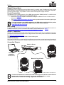
Connection Diagram
For more information about DMX standards or the DMX cables needed to link this product
to a DMX controller, download the DMX Primer from the Chauvet website:
www.chauvetprofessional.com.
The three LED indicators in between the ethernet through ports indicate a connection to a
network and activity on that network. They do not indicate whether or not the
Maverick Force 2 Profile is receiving a signal from a controller.
Computer/
Controller
(running Art-Net™
or sACN protocol)
Switch or Router
Maverick Force 2 Profile
To other Art-Net™ or sACN devices

10
Operation
Maverick Force 2 Profile User Manual Rev. 7
4. Operation
Touchscreen Control Panel
The Maverick Force 2 Profile has a touchscreen display as well as 6 control buttons. Navigate the menu
structure by pressing the buttons, touching the images of the buttons on the sides of the display, or
touching the desired menu option on the display directly. The touchscreen can be locked and calibrated
through the Setup options in the menu. (See Touchscreen Calibration and Touchscreen Lock.)
Control Panel Description
Battery Powered Display
The Maverick Force 2 Profile has a battery powered display which enables access to the menu when the
product is powered off. Press and hold <MENU> until the display activates (approximately 15 seconds).
Home Screen
The Maverick Force 2 Profile has a home screen that shows the current control protocols, personalities,
starting addresses, IP addresses, and universes. To see the home screen, press <MENU> repeatedly until
it shows on the display. From the home screen, touch any of the displayed control settings to immediately
jump to that part of the menu, such as the personality, starting address, or universe, or press <ENTER> to
reach the main menu.
Control Panel Lock
The setting locks or unlocks the control panel.
1. Go to the Settings main level.
2. Select the Lock Screen option.
3. Select NO (control panel stays unlocked) or YES (locks control panel).
Passcode
After being prompted to enter the passcode, press <UP>, <DOWN>, <UP>, <DOWN>, <ENTER>.
Technician Mode
The technician mode disables the pan and tilt motors, allowing the output of the product to be aimed by hand.
To enable the technician mode of the Maverick Force 2 Profile, hold <UP> and <LEFT> while the product
is powering on. When the product is turned off and back on, the pan and tilt will return to normal function.
Button Name Function
<UP> Navigates upwards through the menu list or increases the numeric value when in a
function
<MENU> Exits from the current menu or function
<DOWN> Navigates downwards through the menu list or decreases the numeric value when in
a function
<LEFT> Navigates leftwards through the menu list
<ENTER> Enables the currently displayed menu or sets the currently selected value into the
selected function
<RIGHT> Navigates rightwards through the menu list
When the control panel lock is activated, the product will prompt for the passcode in order
to access the menu. Enter the passcode as described below.

11
Maverick Force 2 Profile User Manual Rev. 7
Operation
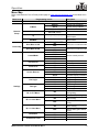
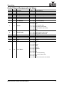
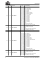
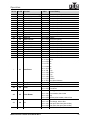
Menu Map
Refer to the Maverick Force 2 Profile product page on www.chauvetprofessional.com for the latest menu
map.
Main Level Programming Levels Description
Address 001–480 Sets the starting address
Network
Setup
IP Mode
Manual Manually set IP address
DHCP Network sets IP address
Static Product sets IP address
Universe 000–255 (Art-Net™)
001–256 (sACN) Sets the universe
Ip _ _ _._ _ _._ _ _._ _ _ Sets the IP address in
Manual mode
SubMask _ _ _._ _ _._ _ _._ _ _ Sets the Subnet Mask in
Manual mode
Personality
Dmx Mode 33 CH NO Selects the 33-channel mode
YES
Dmx Mode 50 CH NO Selects the 50-channel mode
YES
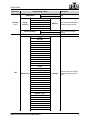
Settings
ControlMode
DMX
Sets the control protocol
WDMX
ArtNet
sACN
Pan Reverse NO Normal pan
YES Reversed pan
Tilt Reverse NO Normal tilt
YES Reversed tilt
Screen Reverse
NO Normal display
YES Inverted display
AUTO Automatic display orientation
Pan Angle
540 540° pan range
360 360° pan range
180 180° pan range
Tilt Angle
270 270° tilt range
180 180° tilt range
90 90° tilt range
BL. O. P/T Move NO Do not black out while
panning/tilting
YES Blackout while panning/tilting
BL. O. Color Move
NO Do not black out while color
wheel moving
YES Blackout while color wheel
moving
BL. O. Gobo Move
NO Do not black out while gobo
wheels moving
YES Blackout while gobo wheels
moving
Calibration NO Cancel calibration
YES Calibrate touchscreen
Touchscreen Lock NO Touch screen enabled
YES Touch screen disabled

12
Operation
Maverick Force 2 Profile User Manual Rev. 7
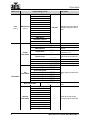
Settings
(cont.)
Lock Screen NO Lock the buttons and touch
screen. Passcode: 0920
YES
Swap XY
NO Do not swap pan and tilt
YES Pan controls tilt, tilt controls
pan
WDMX Reset NO Do not reset WDMX
YES Reset WDMX
Backlight Timer
30S Display turns off after 30
seconds
1M Display turns off after 1
minute
5M Display turns off after 5
minutes
ON Display stays on
Loss of Data Hold Holds last signal received
Close Blacks out fixture
Fans
Auto Fan speed according to
product temperature
Full Fan speed set on high
ECO Quiet mode
TV25
Maintains LED output up to
an ambient temperature of
77 °F (25 °C) (TV25) or 95 °F
(35 °C) (TV35).
TV35
When using these fan modes,
please set the PWM Options
to 6000Hz or 15000Hz to
prevent any possible
harmonization noise.
Dimmer Curve
Linear
Set the dimmer curve
Square
I Squa
SCurve
Linear2
PWM Option
600Hz
Sets the Pulse Width
Modulation frequency
1200Hz
4000Hz
6000Hz
15000Hz
LED POWER 064–255 Sets the maximum LED
output
Min Zoom Focus NO Enables/disables minimum
zoom focus
YES
Preset Select
PRESET A Recorded preset menu
options
PRESET B
PRESET C
Preset Sync
NO Allows recorded preset menu
options to be transferred to
other Maverick Force 2 Profile
fixtures in the DMX daisy chain
YES
Main Level Programming Levels Description

13
Maverick Force 2 Profile User Manual Rev. 7
Operation
Settings
(cont.)
USB Update NO Enables/disables updating by
USB
YES
Reset
Function
Pan/Tilt
NO/YES Reset individual functions or
all functions from start-up
Iris/Prism
Color/CMY/Blade
Gobo/Gobo Rotate
Frost
All
Factory Settings NO Reset to factory default
settings
YES
Test
Auto Test Auto test all functions
Manual Test
Pan
000–255
Manually control and test all
settings through the control
panel
Pan Fine
Tilt
Tilt Fine
P/T Speed
Dimmer
Dimmer Fine
Shutter
Virtual Shaking
Cyan
Magenta
Yellow
CTO
Color
Gobo
Gobo Rotate
Gobo Index
Gobo2
Gobo2 Rotate
Gobo2 Index
Blade1- 1
Blade1- 1 Fine
Blade1- 2
Blade1- 2 Fine
Blade2- 1
Blade2- 1 Fine
Blade2- 2
Blade2- 2 Fine
Blade3- 1
Blade3- 1 Fine
Blade3- 2
Blade3- 2 Fine
Blade4- 1
Blade4- 1 Fine
Blade4- 2
Blade4- 2 Fine
Main Level Programming Levels Description

14
Operation
Maverick Force 2 Profile User Manual Rev. 7
Test
(cont.)
Manual Test
(cont.)
Blade Rotate
000–255
Manually control and test all
settings through the control
panel
Blade. Rota Fine
Focus
Focus Fine
Focus Auto
Zoom
Zoom Fine
Prism
Prism Rotate
Iris
Frost
CMY Macro
CMY Macro Speed
Special Function
Information
Fixture
Information
Ver V_ Shows firmware version
Running Mode _ _ _ Shows current running mode
DMX Address _ _ _ Shows current starting
address
Temperature _ _ _
Shows current product
temperature in °C
Fixture Hours _ _ _ _ _
Shows number of hours
product has been powered
on
Ip _ _ _ _ _ _ _ _ Shows current IP address
SubMask _ _ _ _ _ _ _ _ Shows current Subnet Mask
MAC _ _ _ _ _ _ _ _ Shows current MAC address
Fan
Information
head Fan1 Speed _ _ _ _
Shows speed of head fans in
rpm
head Fan2 Speed _ _ _ _
head Fan3 Speed _ _ _ _
head Fan4 Speed _ _ _ _
Base Fan1 Speed _ _ _ _
Base Fan2 Speed _ _ _ _
Base Fan3 Speed _ _ _ _
Base Fan4 Speed _ _ _ _
Error Information _ _ _ _ _ Shows any errors, or No
Error!
Channel
Information
Frequency
_ _ _ Shows all current values
from input signals, 000–255
Pan
Pan Fine
Tilt
Tilt Fine
P/T Speed
Dimmer
Dimmer Fine
Shutter
Virtual Shaking
Cyan
Magenta
Main Level Programming Levels Description

15
Maverick Force 2 Profile User Manual Rev. 7
Operation
Information
(cont.)
Channel
Information
(cont.)
Yellow
_ _ _ Shows all current values
from input signals, 000–255
CTO
Color
Gobo
Gobo Rotate
Gobo Index
Gobo2
Gobo2 Rotate
Gobo2 Index
Blade1- 1
Blade1- 1 Fine
Blade1- 2
Blade1- 2 Fine
Blade2- 1
Blade2- 1 Fine
Blade2- 2
Blade2- 2 Fine
Blade3- 1
Blade3- 1 Fine
Blade3- 2
Blade3- 2 Fine
Blade4- 1
Blade4- 1 Fine
Blade4- 2
Blade4- 2 Fine
Blade Rotate
Blade. Rota Fine
Focus
Focus Fine
Focus Auto
Zoom
Zoom Fine
Prism
Prism Rotate
Iris
Frost
CMY Macro
CMY Macro Speed
Special Function
Main Level Programming Levels Description

16
Operation
Maverick Force 2 Profile User Manual Rev. 7
Control Configuration
Use control configurations to operate the product with a DMX, Art-Net™, or sACN controller.
Control Mode
The Maverick Force 2 Profile works with wired DMX, WDMX, Art-Net™, and sACN control signals. To
select which protocol to use:
1. Go to the Settings main level.
2. Select the ControlMode option.
3. Select the desired protocol, from DMX, WDMX, ArtNet, or sACN.
Control Personalities
To set the control personality:
1. Go to the Personality main level.
2. Select the desired personality, from Dmx Mode 33 CH or Dmx Mode 50 CH.
Starting Address
Each product will respond to a unique starting address from the controller. All products with the same
starting address will respond in unison. To set the starting address:
1. Go to the Address main level.
2. Select the starting address (001–480).
• The highest recommended starting address for Dmx Mode 33 CH is 480.
• The highest recommended starting address for Dmx Mode 50 CH is 463.
Network Setup
The Network Setup settings control the IP address, subnet mask, and universe of the product.
IP Mode
To choose how the IP address is set:
1. Go to the Network Setup main level.
2. Select the IP Mode option.
3. Select the desired IP mode, from Manual (to set a custom IP address), DHCP (the IP address is
assigned by the connected network), or Static (the product uses a default, preset IP address).
Universe
To assign an Art-Net™ or sACN universe to the Maverick Force 2 Profile:
1. Go to the Network Setup main level.
2. Select the Universe option.
3. Set the universe, from 000–255 (for Art-Net™) or from 001–256 (for sACN).
Manual IP Address
To set the IP address when the IP Mode is set to Manual:
1. Go to the Network Setup main level.
2. Select the Ip option.
3. Set the 4 values of the IP address from 000–255.
Subnet Mask
To set the subnet mask:
1. Go to the Network Setup main level.
2. Select the SubMask option.
3. Set the 4 values of the subnet mask from 000–255.
•See the WDMX Reset section for further setup of WDMX.
•See the Network Setup section for further setup of ethernet protocols (Art-Net™ or sACN).
•See the Starting Address section for the highest selectable starting address for each
personality.
• Make sure that the starting addresses on the various products do not overlap due to the new
personality setting.
Page is loading ...
Page is loading ...
Page is loading ...
Page is loading ...
Page is loading ...
Page is loading ...
Page is loading ...
Page is loading ...
Page is loading ...
Page is loading ...
Page is loading ...
Page is loading ...
Page is loading ...
Page is loading ...
-
 1
1
-
 2
2
-
 3
3
-
 4
4
-
 5
5
-
 6
6
-
 7
7
-
 8
8
-
 9
9
-
 10
10
-
 11
11
-
 12
12
-
 13
13
-
 14
14
-
 15
15
-
 16
16
-
 17
17
-
 18
18
-
 19
19
-
 20
20
-
 21
21
-
 22
22
-
 23
23
-
 24
24
-
 25
25
-
 26
26
-
 27
27
-
 28
28
-
 29
29
-
 30
30
-
 31
31
-
 32
32
-
 33
33
-
 34
34


Chauvet Professional Maverick Force 2 Profile User manual
- Category
- Floodlights
- Type
- User manual
Ask a question and I''ll find the answer in the document
Finding information in a document is now easier with AI
Related papers
-
Chauvet Professional MAVERICK User manual
-
Chauvet Professional MAVERICK FORCE S PROFILE User manual
-
Chauvet Professional Maverick Storm 2 Profile User manual
-
-
Chauvet Professional Maverick Force 3 Profile User manual
-
-
Chauvet Professional MAVERICK User manual
-
Chauvet Professional Maverick Force 1 Spot User manual
-
-