Page is loading ...

The Ultimate Connection
CONTINENTAL INDUSTRIES
The Ultimate Connection
34-6034-90
ECN 2620 REV "E" 07/23/14
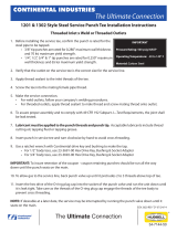
1201 & 1302 Style Steel Service Punch Tee Installation Instructions
Weld Inlet x Metallic Pipe (Conductive) Compression Outlet
1. Before installing the service tee, conrm the punch is rated for the
steel pipe to be tapped.
• 3/8" tip punches are rated for 0.280" maximum wall thickness
and 70 ksi maximum yield strength.
• 1/4", 1/2", 3/4" & 1" tip punches are rated for 0.250" maximum
wall thickness and 65 ksi maximum yield strength.
2. Verify that the outlet on the service tee is the correct size for
the service line.
3. Remove the O-ring cap, the punch, outlet seal ring and compression nut from the service tee and place
in the plastic bag in which the service tee was shipped. Do not remove the splatter shield from the inlet.
4.
Clean the main of all coatings, rust, dirt, etc., in the area where the service tee is to be welded onto the main
.
5. Weld service tee to main per your company's welding procedures.
6. Make the service connection. See other side for outlet assembly instructions.
7. To assure proper assembly and to comply with 49 CFR 192 Subpart J—Test Requirements, the joint shall
be leak tested.
8. The service tee must be cool to the touch before reinserting the punch.
9. Lubricant must be applied to the punch threads and punch tip. Acceptable lubricants include thread
cutting oil, tapping uid or tapping grease.
10. Insert punch in service tee and turn clockwise by hand to avoid cross threading.
11. Use a ratchet wrench with Continental adapter key and bushing to make the tap.
• For 1/2" body tees, use 23-3691-00 Hex Drive Key, Bushing & Socket Adapter
• For 3/4" body tees, use 23-3692-00 Hex Drive Key, Bushing & Socket Adapter
IMPORTANT: To insure retention of the coupon - coupon retaining punches should be run all the way
down until the punch seats on the main.
12. To allow gas to the service line, back punch valve up until it protrudes 2 to 3 threads above top of tee.
13. Insert the hex drive of the O-ring plug cap into the socket of the punch valve and run the unit down until
it is leak tight. Take care as the threads of the O-ring plug cap engage the threads of the tee body to
prevent cross threading.
NOTE: If desirable at a later date, the service may be interrupted by running the punch valve down until it
seats on the main.
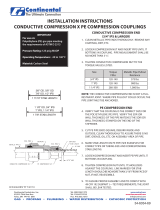
IMPORTANT
Pressure Rating: 300 psig MAOP
Operating Temperature: -20 to 140° F
Material: Carbon Steel

Size Metallic Pipe Pullout
Resistance
1/2" OD 500 lbs
5/8" OD 2,000 lbs
1/2" OD & 5/8" OD Conductive Compression Outlets
1. Clean metallic pipe ends thoroughly. Remove any coatings, dirt, etc.
2. Loosen compression nut and insert pipe until it bottoms in coupling.
3. Tighten compression nut until it bottoms on shoulder (metal to metal).
NOTE: The conductive compression end is not a full restraint joint. WHERE PIPE PULLOUT COULD OCCUR,
THE PIPE JOINT MUST BE ANCHORED.
3/4" IPS & Larger Conductive Compression Outlets
1. Clean metallic pipe ends thoroughly. Remove any coatings, dirt, etc.
2. Loosen compression nut and insert pipe until it bottoms in coupling. Pipe misalignment shall be no
more than 3 ½°.
3. Tighten conductive compression nut to the torque values listed.
Size Torque
Ftlbs
Metallic Pipe Pullout
Resistance
3/4" IPS 120-140 575 lbs
1" IPS 120-140 900 lbs
1 1/4" IPS 280-300 1,000 lbs
NOTE: The conductive compression end is not a full restraint joint. WHERE PIPE PULLOUT COULD OCCUR,
THE PIPE JOINT MUST BE ANCHORED.
/


